We help the world since 2012

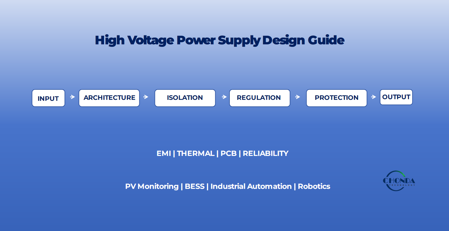
High Voltage Power Supply Design Guide
Introduction: What Does High-Voltage Power Supply Design Involve?
High-voltage power supply design is more than simply converting one voltage to another. For industrial and embedded systems, the power supply must work reliably under real electrical, thermal, mechanical, and environmental conditions while meeting the required isolation, regulation, protection, and electromagnetic compatibility requirements.
A high-voltage power supply may need to handle a wide input-voltage range, provide a stable output, maintain electrical isolation, and operate safely under transient and abnormal conditions. The design may also need to balance efficiency, power density, thermal performance, EMI, reliability, and cost.
Depending on the application, the required power architecture may include:
- AC-DC power conversion
- Isolated DC-DC conversion
- Transformer-based power architectures
- High-frequency switching stages
- Custom power-conversion solutions
The correct architecture therefore depends on the complete system requirements rather than a single specification such as input voltage or rated power.
For engineers designing high-voltage power systems, several questions should be considered from the beginning:
- What are the required input and output voltage ranges?
- Is galvanic isolation required?
- How much power and output current are needed?
- How tightly must the output be regulated?
- What are the efficiency and thermal requirements?
- How sensitive is the system to EMI and electrical noise?
- What protection functions are required?
- What creepage, clearance, and insulation requirements apply?
- How much PCB space and mechanical space are available?
- Is a standard power module sufficient, or is a customized solution required?
This guide provides a practical framework for evaluating these factors and understanding the major engineering considerations involved in high-voltage power supply design.
The goal is not to recommend one universal topology, but to help engineers identify the power-conversion architecture that best matches the electrical, isolation, thermal, EMI, reliability, and application requirements of the final system.
1. Define the Power Supply Requirements First
Before selecting a topology or power module, engineers should first define the electrical and application requirements of the power supply.
A high-voltage power supply that is suitable for one system may not be suitable for another, even when the nominal input voltage is similar. Input range, output requirements, isolation, transient conditions, thermal limits, and installation environment can all affect the final power-conversion architecture.
A practical design process should begin with the following requirements.
1.1 Input Voltage and Operating Range
The first step is to define the actual input-voltage conditions rather than considering only the nominal voltage.
Engineers should identify:
- Nominal input voltage
- Minimum and maximum operating voltage
- DC or AC input
- Input-voltage fluctuations
- Startup voltage conditions
- Transient or surge conditions
For example, a system described as a “1000V DC application” may not actually operate at exactly 1000VDC. The real operating range may include significant variation above and below the nominal value.
For high-voltage DC systems, the maximum continuous input voltage and transient conditions should be considered when selecting the converter and designing the insulation system.
1.2 Output Voltage and Current
The required output should be defined with the same level of detail.
Important parameters include:
- Nominal output voltage
- Required output-voltage range
- Continuous output current
- Peak or transient load current
- Total output power
- Regulation requirements
- Load variation
For example, a monitoring system may require a regulated 24VDC output, while another embedded circuit may require 5VDC or 12VDC.
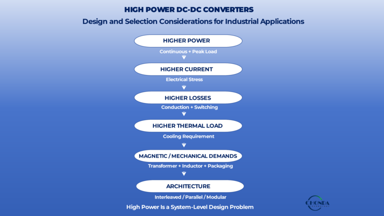
The required output current is equally important because thermal performance, semiconductor selection, magnetic components, and overall converter size are all affected by power level.
1.3 Isolation Requirements
If galvanic isolation is required, it should be defined at the beginning of the design rather than added later.
Engineers should consider:
- Whether input and output must be electrically isolated
- Required isolation voltage
- Working voltage
- Creepage distance
- Clearance distance
- Insulation system
- Applicable safety requirements
Isolation requirements affect not only the transformer or power module but also the PCB layout, mechanical construction, connector selection, and overall system architecture.
1.4 Power Rating and Load Profile
The rated power of a converter should be selected according to the actual load profile rather than only the nominal operating condition.
Engineers should consider:
- Continuous load
- Peak load
- Startup load
- Inrush current
- Duty cycle
- Future load expansion
A power supply operating close to its maximum rating continuously may experience greater thermal stress and reduced design margin.
For demanding industrial applications, sufficient electrical and thermal margin should be considered during the initial design stage.
1.5 Environmental and Mechanical Conditions
Electrical specifications alone are not enough.
The power supply may also need to operate under:
- High or low ambient temperature
- Limited airflow
- High humidity
- Dust or pollution
- Vibration
- Altitude
- Restricted installation space
Mechanical requirements such as PCB dimensions, mounting position, connector orientation, and cooling method can also influence the power-conversion architecture.
1.6 Define the Requirements Before Selecting the Topology
Once the main requirements have been identified, engineers can begin comparing possible power-conversion architectures.
A useful minimum requirement set includes:
Input → Output → Power → Isolation → Regulation → Environment → Mechanical Constraints
Only after these requirements are clear should engineers decide whether the system is better suited to:
- A transformer-based architecture
- An isolated DC-DC converter
- An AC-DC power module
- A multi-stage power-conversion system
- A customized power solution
Starting with the requirements rather than a specific component helps avoid selecting a converter that meets one parameter but creates problems elsewhere in the system.
2. Choose the Right Power-Conversion Architecture
Once the electrical and application requirements have been defined, the next step is to select an appropriate power-conversion architecture.
There is no single power-supply topology that is ideal for every high-voltage application. The most suitable architecture depends on the input source, required output, isolation requirements, power level, regulation, efficiency, thermal conditions, mechanical constraints, and system environment.
Common power-conversion architectures include transformer-based systems, isolated DC-DC converters, AC-DC power supplies, and custom multi-stage solutions.
2.1 Transformer-Based Power Architecture
A transformer-based architecture is commonly considered when the system operates from an AC source and requires electrical isolation, voltage transformation, or both.
An isolation transformer transfers AC energy through magnetic coupling while keeping the primary and secondary circuits electrically separated.
This type of architecture can be appropriate when:
- The input and output are both AC.
- Galvanic isolation is a primary requirement.
- AC voltage transformation is required.
- A relatively simple magnetic power-transfer stage is preferred.
- DC regulation is not required directly from the transformer.
For applications that require regulated DC power after isolation, additional rectification, filtering, or regulation stages may be required.
For a more detailed comparison between transformer-based and isolated DC-DC architectures, see our guide on Isolation Transformer vs Isolated DC-DC Converter.
2.2 Isolated DC-DC Architecture
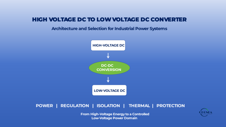
An isolated DC-DC converter is a practical architecture when the system starts with DC power and requires an isolated and regulated DC output.
A typical isolated DC-DC converter combines:
- Input switching
- High-frequency magnetic isolation
- Rectification
- Output filtering
- Feedback and regulation
- Protection functions
This architecture is particularly useful when the input voltage is high or varies over a defined range and the downstream electronics require a stable lower-voltage DC supply.
Typical applications include:
- PV string monitoring systems
- Solar combiner box monitoring
- Battery energy storage systems
- Industrial automation
- Robotics and embedded systems
- Industrial control electronics
For a deeper explanation of isolated DC-DC architecture, see What Is a High Voltage DC-DC Converter? and High Voltage DC-DC Converter Isolation Design.
2.3 AC-DC Power Architecture
When the available power source is AC and the final equipment requires DC power, an AC-DC power architecture may be more appropriate.
An AC-DC power supply can integrate functions such as:
- Input rectification
- Power-factor correction where required
- Switching conversion
- Isolation
- Output regulation
- Protection
- Filtering
The appropriate topology depends on the input voltage, output requirements, power level, efficiency targets, regulatory requirements, and application environment.
AC-DC power modules are commonly used to provide auxiliary or system-level DC power for industrial equipment, control systems, embedded electronics, and other applications.
2.4 Multi-Stage and Custom Power Architectures
Some high-voltage applications cannot be served effectively by a single standard power stage.
A system may require multiple conversion stages, for example:
AC Input → AC-DC Stage → High-Voltage DC Bus → Isolated DC-DC Stage → Regulated Low-Voltage Output
A custom architecture may also be required when the application has unusual input ranges, special isolation requirements, restricted mechanical dimensions, unusual output characteristics, or demanding environmental conditions.
In these situations, the power supply should be considered as a complete system rather than as an isolated component.
How to Choose the Architecture
A practical approach is to begin with four basic questions:
1. What is the input source?
AC and DC inputs generally lead to different power-conversion architectures.
2. What is the required output?
AC output, regulated DC output, and multiple output rails may require different approaches.
3. Is galvanic isolation required?
If isolation is required, the architecture must provide the appropriate isolation barrier and insulation system.
4. How complex are the system requirements?
A standard module may be sufficient for a well-defined application, while a customized or multi-stage architecture may be more appropriate for complex systems.
Selecting the architecture early helps engineers avoid unnecessary conversion stages, excessive component count, thermal problems, and difficult EMI issues later in the design process.
The architecture should therefore be selected as part of the overall system design rather than as an isolated component decision.
3. High-Voltage Isolation and Insulation Design
Isolation is one of the most important design considerations in a high-voltage power supply.
In a high-voltage system, electrical isolation is not simply a matter of selecting a component with a high isolation-voltage rating. The isolation system must be considered as part of the complete power architecture, including the transformer or isolation component, PCB layout, insulation materials, connectors, mechanical construction, and the operating environment.
A reliable isolation design should provide the required electrical separation while maintaining adequate safety margin throughout the expected operating conditions.
3.1 Galvanic Isolation
Galvanic isolation means that there is no direct conductive path between two electrically separated circuits.
In an isolated power supply, the input and output sides can therefore operate at different electrical potentials while energy is transferred through an appropriate isolation mechanism.
Depending on the power-conversion architecture, isolation may be provided through:
- An isolation transformer
- A high-frequency transformer in an isolated DC-DC converter
- Other application-specific isolation components
The required isolation approach depends on the system topology, working voltage, power level, and applicable safety requirements.
3.2 Working Voltage vs. Isolation Voltage
Working voltage and isolation voltage are related but should not be treated as the same specification.
Working voltage refers to the voltage that the insulation system is expected to withstand continuously during normal operation.
Isolation voltage, often specified as a dielectric or withstand voltage, refers to a test condition used to verify the insulation system under a defined applied voltage for a specified duration.
A power supply may therefore have a high isolation-test rating while still requiring careful evaluation of its actual continuous working voltage and insulation system.
For high-voltage applications, engineers should consider both values together with the applicable insulation-coordination requirements.
3.3 Creepage Distance
Creepage distance is the shortest distance between two conductive parts measured along the surface of an insulating material.
Adequate creepage helps reduce the risk of surface tracking and unintended conduction across an insulation barrier.
The required creepage distance depends on factors such as:
- Working voltage
- Pollution degree
- Insulation type
- Material characteristics
- Altitude
- Applicable safety requirements
For PCB-based power supplies, creepage must be considered across the entire insulation path, including traces, pads, connectors, component bodies, and other conductive structures.
3.4 Clearance Distance
Clearance is the shortest distance through air between two conductive parts.
Unlike creepage, clearance does not follow the PCB surface.
Adequate clearance helps reduce the risk of electrical breakdown across an air gap, particularly when high voltages or transient conditions are present.
Clearance requirements depend on the operating conditions and applicable insulation-coordination requirements. Engineers should therefore determine the appropriate value from the relevant standards and application conditions rather than relying on a single universal spacing rule.
3.5 Isolation Barriers and PCB Design
The isolation barrier should be treated as a physical design boundary.
Unnecessary conductive structures should not cross the barrier, including:
- Copper pours
- Traces
- Vias
- Test points
- Mounting hardware
- Conductive shields
- Connector structures
Where additional creepage distance is required, PCB slots, cutouts, or other mechanical features may be considered as part of the insulation design.
The barrier also needs to be considered together with transformer construction, component placement, connector selection, and the mechanical enclosure.
3.6 Insulation Coordination
Insulation coordination considers the relationship between the electrical environment, insulation system, and required distances.
For high-voltage equipment, engineers may need to evaluate:
- Normal operating voltage
- Transient overvoltage
- Pollution conditions
- Altitude
- Insulation level
- Material characteristics
- Creepage and clearance
IEC 60664-1 provides principles and requirements for insulation coordination, including creepage, clearance, and solid insulation within its scope. The applicable edition and specific requirements should always be verified for the final equipment and application. (IEC 60664-1)
3.7 Isolation Is a System-Level Requirement
A common mistake is to treat isolation as a specification belonging only to the transformer or DC-DC converter.
In practice, the complete isolation system includes:
Power Component → PCB → Connectors → Insulation Materials → Mechanical Structure → Operating Environment
A converter may pass a dielectric-strength test and still require further attention to creepage, clearance, contamination, thermal stress, or mechanical spacing in the final equipment.
For this reason, isolation should be considered from the earliest stage of power-supply architecture and PCB design.
For a deeper discussion of isolated DC-DC converter isolation design, see High Voltage DC-DC Converter Isolation Design: Principles and Applications. PCB-specific considerations are covered in High Voltage DC-DC Converter PCB Design Considerations.
A robust high-voltage power supply therefore combines the required electrical isolation rating with an insulation system and physical design that remain reliable throughout the intended operating conditions.
4. Voltage Regulation and Power Conversion
Once the power-supply requirements and overall architecture have been defined, the next step is to ensure that electrical energy can be converted into a stable and usable output.
In a practical high-voltage power supply, the input voltage may change, the load may vary, and switching conditions may introduce dynamic disturbances. The power-conversion stage therefore needs to manage these changes while maintaining the required output voltage and current.
4.1 Input Variation and Output Regulation
A power supply should be evaluated over its actual operating range rather than only at the nominal input voltage.
For example, a high-voltage DC source may fluctuate significantly during normal operation or under system transients. The converter must be designed to operate within its specified input range while maintaining the required output conditions.
Output regulation is affected by factors such as:
- Input-voltage variation
- Load variation
- Switching conditions
- Control-loop response
- Component tolerances
- Temperature
A well-designed converter uses an appropriate control strategy to keep the output within the required regulation range.
4.2 Closed-Loop Regulation
Many regulated power supplies use feedback to monitor the output and adjust the power-conversion process.
A simplified control sequence is:
Output Voltage → Feedback → Controller → Switching Stage → Output
If the output voltage changes because of input variation or load changes, the control system can adjust the switching behavior to compensate.
The actual control method depends on the converter topology and application requirements.
In isolated converters, feedback across the isolation barrier may use dedicated isolation components or communication methods appropriate to the selected architecture.
4.3 Voltage Conversion and Duty-Cycle Control
In switching power supplies, output voltage is controlled by managing how energy is transferred through the power-conversion stage.
Depending on the topology, the control system may adjust parameters such as:
- Duty cycle
- Switching frequency
- Phase relationship
- Current limit
- Power-transfer timing
The exact control method depends on the topology, semiconductor devices, magnetic design, and required operating range.
The goal is to provide the required output while maintaining acceptable efficiency, thermal performance, and system stability.
4.4 Regulation Under Dynamic Loads
Industrial and embedded systems may not always operate at a constant load.
A monitoring circuit may normally consume relatively little power but require additional current during communication or measurement events.
A controller therefore needs to respond to changes in load while keeping the output within the required limits.
Important characteristics may include:
- Load regulation
- Transient response
- Startup behavior
- Recovery time
- Output ripple
These characteristics should be evaluated against the requirements of the downstream electronics rather than using a single regulation figure in isolation.
4.5 Power Conversion Efficiency
Voltage regulation and efficiency must be considered together.
A converter that maintains a tightly controlled output but generates excessive losses may create thermal problems or require larger cooling systems.
Power losses can come from:
- Semiconductor conduction
- Switching transitions
- Transformer or inductor losses
- Rectification
- Gate-drive circuits
- PCB and interconnect resistance
The power-conversion stage should therefore be designed to meet both the electrical regulation requirements and the required efficiency target.
4.6 Output Requirements Depend on the Application
Not every power supply requires the same level of regulation.
For example:
- A simple auxiliary load may tolerate a wider output range.
- A sensor or analog measurement circuit may require a tightly controlled supply.
- A communication interface may have specific ripple or transient requirements.
- A digital processor may require a stable rail within a defined tolerance.
The required regulation level should therefore be established from the downstream load requirements.
4.7 Power Conversion Is a System-Level Function
Voltage regulation should not be considered separately from the rest of the power supply.
Input conditions, switching topology, magnetic components, feedback control, thermal performance, PCB layout, filtering, and protection all interact with the regulation behavior.
For this reason, engineers should evaluate the complete conversion chain:
Input → Power Conversion → Isolation Where Required → Regulation → Filtering → Load
A stable output is ultimately the result of the entire power-conversion architecture working together rather than a single control component.
For more detailed discussions of high-voltage DC-DC converter principles and selection, see:
What Is a High Voltage DC-DC Converter?
and
DC-DC Converter Selection Guide: Key Parameters for High Voltage Applications.
5. Switching Frequency, Efficiency, and Power Density
Switching frequency is an important design parameter in modern power supplies because it affects the size of magnetic components, power density, efficiency, thermal performance, and electromagnetic compatibility.
In general, increasing switching frequency can allow transformers and inductors to be made smaller for a given power level. This can help reduce the overall size of a power-conversion stage and make higher power density possible.
However, higher switching frequency does not automatically result in a better power supply.
5.1 Why Switching Frequency Matters
In switching power supplies, energy is transferred in repeated high-frequency switching cycles.
A higher switching frequency can allow magnetic components to transfer energy using smaller physical structures. This is one reason why high-frequency isolated DC-DC converters can be much more compact than traditional low-frequency transformer-based solutions.
However, the benefits of higher frequency must be balanced against the additional losses and EMI challenges introduced by faster switching.
5.2 Switching Losses
As switching frequency increases, semiconductor devices may perform more switching transitions per unit of time.
This can increase switching losses associated with:
- Turn-on and turn-off transitions
- Gate-drive requirements
- Parasitic capacitance
- Reverse-recovery behavior where applicable
The actual loss depends on the semiconductor technology, switching speed, voltage, current, topology, and operating conditions.
Therefore, selecting a higher switching frequency requires careful evaluation of the complete switching stage rather than considering frequency alone.
5.3 Magnetic Losses
Higher switching frequency can reduce the physical size of magnetic components, but the magnetic design becomes increasingly important.
Engineers may need to consider:
- Core material
- Core losses
- Winding losses
- Skin effect
- Proximity effect
- Magnetic flux density
- Winding arrangement
- Thermal conditions
The transformer or inductor must operate within an appropriate magnetic and thermal range over the intended input, output, and load conditions.
A smaller magnetic component is not necessarily better if the resulting design introduces excessive core or winding losses.
5.4 Efficiency and Thermal Trade-Offs
A high-voltage power supply must balance efficiency and power density.
Higher frequency can reduce magnetic size, but increased switching and magnetic losses can increase the total heat generated by the converter.
Higher losses may then require:
- Larger thermal paths
- Heat sinks
- Improved airflow
- Better PCB copper distribution
- Lower operating temperature
- Reduced output power or derating
The thermal design should therefore be considered together with switching frequency and efficiency rather than treated as a separate issue.
5.5 Power Density
Power density describes how much power can be delivered within a given physical volume or area.
Higher power density can be valuable when:
- PCB space is limited
- The enclosure size is restricted
- Weight is important
- The converter must be integrated into compact equipment
High-frequency switching, compact magnetic components, and optimized semiconductor selection can all contribute to higher power density.
However, higher power density also increases thermal density and may make EMI control more difficult.
A practical design therefore aims for an appropriate balance rather than maximizing power density at any cost.
5.6 Switching Frequency and EMI
Fast switching edges can produce high dv/dt and di/dt, which may increase electromagnetic noise.
As switching frequency and switching speed increase, engineers should pay greater attention to:
- Switching-loop area
- PCB layout
- Parasitic capacitance
- Parasitic inductance
- Grounding
- Shielding
- Input and output filtering
This is particularly important in systems containing precision measurement, communication, monitoring, or control electronics.
For more detailed discussions, see High Voltage DC-DC Converter EMI Design Considerations and High Voltage DC-DC Converter PCB Design Considerations.
5.7 Finding the Right Balance
There is no universally optimal switching frequency for every high-voltage power supply.
The appropriate operating point depends on:
Power Level + Input Voltage + Topology + Magnetic Design + Semiconductor Technology + Thermal Conditions + EMI Requirements
A well-designed converter therefore seeks an operating frequency that provides an appropriate balance among:
- Efficiency
- Power density
- Thermal performance
- EMI
- Reliability
- Cost
In other words, the goal is not simply to maximize switching frequency or minimize component size.
The goal is to achieve the required system performance within the available electrical, mechanical, thermal, and regulatory constraints.
6. EMI and Noise Control
Electromagnetic interference (EMI) is one of the most important system-level considerations in high-voltage power supply design.
A power supply may meet its voltage, current, and efficiency requirements on paper while still causing problems in the final system because of excessive conducted or radiated noise.
For this reason, EMI should be considered from the beginning of the power-architecture and PCB-design process rather than treated as a final-stage filtering problem.
6.1 Where Does EMI Come From?
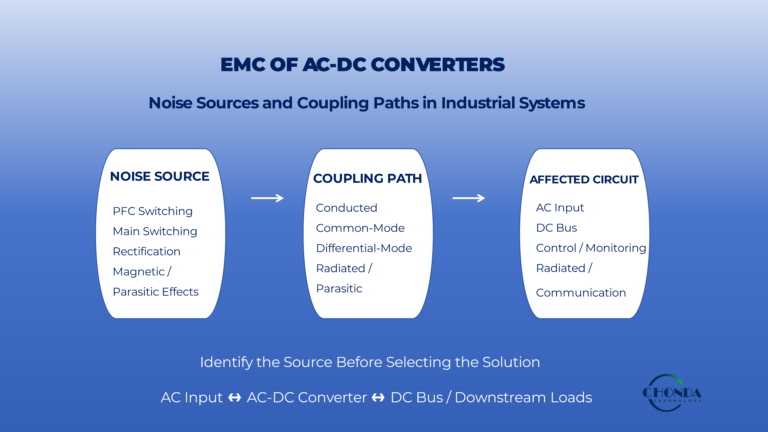
High-voltage switching power supplies can generate electrical noise through several mechanisms.
Common sources include:
- Fast switching voltage transitions
- High di/dt current paths
- Large switching loops
- Transformer and inductor parasitics
- Parasitic capacitance
- Gate-drive signals
- Rectifier switching
- Poorly controlled return paths
In switching converters, rapid changes in voltage and current can excite parasitic inductance and capacitance throughout the power stage.
The resulting noise may then propagate through conductive paths or couple into nearby circuits.
6.2 Conducted and Radiated Noise
EMI can generally reach other parts of the system through conductive or radiated paths.
Conducted noise can travel through:
- Input power lines
- Output power lines
- Ground connections
- Communication cables
- Other conductive interconnections
Radiated noise can occur when high-frequency currents and rapidly changing voltages create electromagnetic fields that couple into nearby traces, cables, components, or enclosures.
The dominant mechanism depends on the converter topology, switching frequency, physical layout, cable arrangement, and system construction.
6.3 Common-Mode and Differential-Mode Noise
Engineers often analyze conducted EMI by separating it into common-mode and differential-mode components.
Differential-mode noise appears between two conductors of the same circuit and is commonly associated with switching currents and current loops.
Common-mode noise appears with respect to a reference such as chassis or ground and can be strongly influenced by parasitic capacitance and high-voltage switching nodes.
Understanding which noise mode is dominant can help determine the appropriate control strategy.
6.4 Control EMI at the Source
The most effective EMI strategy is often to reduce noise generation at its source before relying on additional filters.
Important design approaches include:
- Minimize high-current switching-loop area
- Reduce unnecessary high dv/dt copper area
- Keep switching paths short
- Place high-frequency decoupling components close to the switching devices
- Separate noisy power stages from sensitive control circuits
- Provide controlled return paths
- Optimize transformer construction and winding arrangement
These measures can reduce the amount of unwanted energy that is generated and coupled into the rest of the system.
6.5 PCB Layout and Return Paths
PCB layout has a major influence on EMI performance.
Engineers should consider:
- Current-loop geometry
- High dv/dt switching nodes
- Ground-plane structure
- Signal routing
- Isolation barriers
- Return-current paths
- Component placement
A schematic may appear electrically correct while the physical PCB layout creates large current loops or undesirable coupling paths.
For high-voltage converters, the layout must also maintain the required creepage and clearance while controlling high-frequency current paths.
6.6 Filtering and Shielding
Once the major noise sources and coupling paths have been controlled, filtering and shielding can be used to further reduce unwanted emissions.
Depending on the application, this may include:
- Input filters
- Output filters
- Common-mode chokes
- Differential-mode filtering
- Ferrite components
- Shielding
- Chassis or enclosure grounding
Filtering should be designed together with the converter and its source and load conditions.
Simply adding larger capacitors or stronger filters does not always solve an EMI problem if the main noise source or return path remains uncontrolled.
6.7 Transformer and Parasitic Capacitance
In isolated high-voltage converters, transformer construction can have a significant effect on EMI.
Parasitic capacitance between the primary and secondary windings can provide a path for common-mode high-frequency currents across the isolation barrier.
Engineers may therefore need to consider:
- Winding arrangement
- Interwinding capacitance
- Shielding
- Core construction
- Leakage inductance
- PCB placement
Transformer optimization should be considered together with the switching stage and PCB layout rather than as an isolated magnetic-design problem.
6.8 EMI Should Be Considered Early
EMI problems are usually easier and less expensive to solve during the architecture and prototype stages than after a complete system has been built.
A practical design process should consider:
Topology → Switching Behavior → Transformer → PCB Layout → Grounding → Filtering → System Integration
This allows engineers to identify likely coupling paths before the product reaches formal EMC testing.
For more detailed discussions, see High Voltage DC-DC Converter EMI Design Considerations, How to Reduce Electrical Noise in PV Monitoring Systems, and How to Reduce EMI in PV Monitoring Systems.
6.9 System-Level EMI Design
EMI performance is determined by the complete power system rather than by a single component.
The final result depends on the interaction among:
- Power-conversion topology
- Switching frequency
- Semiconductor devices
- Transformer construction
- PCB layout
- Grounding
- Filtering
- Cables and connectors
- Enclosure and mechanical structure
- Load and source characteristics
A reliable high-voltage power supply therefore treats EMI as a system-level design requirement from the beginning.
The objective is not simply to make the converter “quiet.” The objective is to ensure that the complete power system operates reliably without causing unacceptable interference to itself or surrounding equipment.
7. Thermal Management and Reliability
Thermal performance is one of the most important factors affecting the long-term reliability of a high-voltage power supply.
A converter may meet its electrical specifications during initial testing but still experience reduced reliability if excessive heat is generated or if components operate too close to their thermal limits.
For this reason, thermal management should be considered together with efficiency, switching frequency, power density, component selection, PCB layout, and the installation environment.
7.1 Where Does the Heat Come From?
Power losses are converted into heat within the power supply.
Common sources include:
- Semiconductor conduction losses
- Switching losses
- Transformer and magnetic losses
- Rectification losses
- Capacitor losses
- Gate-drive losses
- PCB and interconnection losses
The total heat generated by the converter depends on the operating voltage, current, switching frequency, topology, load level, and component characteristics.
Reducing unnecessary losses is therefore the first step toward good thermal performance.
7.2 Semiconductor Thermal Management
Power semiconductors can become significant heat sources, particularly at high input voltage, high switching frequency, or high output power.
Engineers should consider:
- Device conduction loss
- Switching loss
- Thermal resistance
- Junction temperature
- PCB copper area
- Heat-sink requirements
- Airflow and cooling conditions
The selected semiconductor should not simply meet the electrical voltage and current ratings. Its thermal behavior under the intended operating conditions must also be considered.
7.3 Transformer and Magnetic Thermal Performance
Transformers and inductors can also contribute significantly to total power loss.
Magnetic losses may result from:
- Core losses
- Winding resistance
- Skin effect
- Proximity effect
- Leakage-related losses
As switching frequency or power density increases, magnetic thermal performance becomes increasingly important.
The transformer should therefore be evaluated not only for its electrical isolation and voltage-transformation characteristics, but also for its winding temperature, core temperature, insulation system, and cooling conditions.
7.4 PCB Thermal Paths
The PCB is part of the thermal-management system.
Heat generated by semiconductors and other power components must be transferred through appropriate thermal paths and ultimately removed from the system.
Depending on the design, thermal management may involve:
- Large copper areas
- Thermal vias
- Multilayer PCB structures
- Heat sinks
- Metal enclosures
- Forced or natural airflow
Component placement also matters. High-loss components should not be concentrated in a small area without sufficient thermal paths.
7.5 Ambient Temperature and Derating
A power supply that operates reliably at room temperature may behave differently in a high-temperature enclosure.
Engineers should therefore consider the complete operating environment, including:
- Ambient temperature
- Airflow
- Enclosure size
- Installation location
- Altitude
- Continuous operating load
Derating can be used to maintain additional electrical and thermal margin as operating conditions become more demanding.
The actual derating strategy depends on the converter design, components, application requirements, and manufacturer specifications.
7.6 Reliability Is More Than Component Ratings
Component ratings provide an important starting point, but long-term reliability depends on how components are used in the complete system.
Engineers should consider:
- Electrical stress
- Thermal stress
- Repetitive switching stress
- Voltage transients
- Current transients
- Environmental conditions
- Mechanical stress
- Component aging
A design with components operating permanently at their maximum rated limits may have less margin than a design with appropriately selected components and controlled operating conditions.
7.7 Thermal Design and Electrical Reliability Are Connected
Thermal problems can create secondary electrical problems.
For example, excessive temperature can contribute to:
- Increased component losses
- Reduced component lifetime
- Capacitor degradation
- Semiconductor stress
- Magnetic performance changes
- Insulation aging
- Output-performance drift
This means thermal management should not be treated as a mechanical problem added after the electrical design is complete.
It is part of the electrical reliability strategy.
7.8 Designing for Long-Term Reliability
A reliable high-voltage power supply should be evaluated across its intended operating range rather than only during a short laboratory test.
Engineers should consider:
Input Conditions → Load Profile → Losses → Temperature Rise → Component Stress → Long-Term Reliability
A practical design should maintain adequate margin under expected operating and environmental conditions.
For more detailed discussions, see High Voltage DC-DC Converter Thermal Management and How to Improve High Voltage DC-DC Converter Reliability.
7.9 Reliability Must Be Verified Under Real Conditions
Prototype testing should reflect realistic operating conditions as closely as possible.
Depending on the application, verification may include:
- Full-load testing
- Input-voltage variation
- Thermal testing
- Startup and shutdown testing
- Transient testing
- Protection testing
- Extended-duration operation
- Environmental testing where required
The objective is not only to demonstrate that the converter works, but to confirm that it remains stable and reliable throughout its intended operating conditions.
A high-voltage power supply should therefore be designed with sufficient electrical, thermal, mechanical, and environmental margin from the beginning.
8. Protection Features for High-Voltage Power Supplies
Protection functions are an essential part of high-voltage power-supply design.
A converter may operate correctly under normal conditions, but abnormal events such as input surges, output overloads, short circuits, or excessive temperature can place significant stress on the power stage and connected equipment.
A well-designed protection strategy helps limit electrical and thermal stress, reduce the risk of damage, and improve the overall reliability of the power system.
Protection should therefore be considered during the power-architecture stage rather than added only after the main converter design has been completed.
8.1 Over-Voltage Protection
Over-voltage conditions may occur because of input transients, control-loop faults, switching abnormalities, or unexpected system conditions.
Depending on the architecture, protection may be implemented at the input, output, or both.
Common approaches can include:
- Voltage clamps
- TVS devices
- Surge-protection components
- Control-based shutdown
- Over-voltage detection circuits
The appropriate method depends on the expected transient energy, operating voltage, response time, and system requirements.
8.2 Over-Current and Short-Circuit Protection
Excessive current can increase semiconductor, transformer, PCB, and connector stress.
Over-current protection can help prevent prolonged operation under abnormal load conditions.
Possible approaches include:
- Current sensing
- Cycle-by-cycle current limiting
- Hiccup protection
- Foldback behavior
- Controlled shutdown
Short-circuit conditions should also be considered because the converter may need to recover safely once the fault is removed.
8.3 Over-Temperature Protection
Temperature is closely connected to reliability.
If a semiconductor, transformer, or other critical component exceeds its safe operating temperature, the converter may need to reduce output power or shut down.
Depending on the design, protection may include:
- Temperature sensing
- Thermal shutdown
- Output-current reduction
- Power derating
- Controlled restart
Thermal protection should complement the underlying thermal design rather than compensate for inadequate cooling.
8.4 Input Surge and Transient Protection
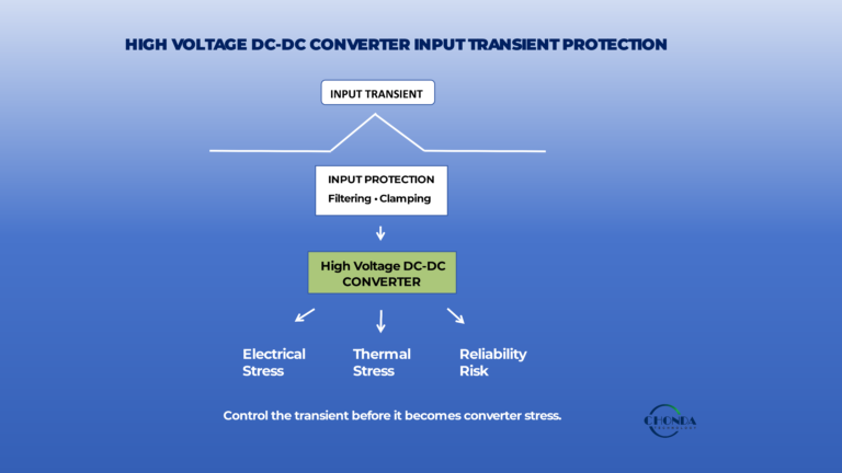
High-voltage power supplies may be exposed to short-duration electrical transients during:
- Startup
- Switching events
- Load changes
- System faults
- External switching equipment
- Energy-storage systems
The protection strategy should consider the expected transient voltage, duration, source impedance, and available energy.
Input protection may include appropriate surge-suppression and filtering components selected for the actual application environment.
8.5 Inrush Current and Startup Protection
Some power supplies draw a higher-than-normal current during startup as capacitors charge and the power stage begins operating.
If the inrush current is not controlled, it can place unnecessary stress on:
- Input protection components
- Switches
- Connectors
- Fuses
- Upstream power systems
Depending on the architecture, engineers may consider:
- Soft-start control
- Inrush-current limiting
- Pre-charge circuits
- Controlled switching
Startup behavior should be evaluated together with the upstream power source and downstream load.
8.6 Reverse-Polarity and Incorrect-Connection Protection
Where the application permits incorrect wiring or polarity reversal, additional protection may be required.
Possible methods include:
- Series protection devices
- MOSFET-based protection
- Fuses
- Electronic disconnects
The appropriate approach depends on the input architecture and expected fault conditions.
Not every high-voltage converter requires reverse-polarity protection, so this function should be included only when it matches the real system risk.
8.7 Protection and Normal Operating Performance
Protection functions should not interfere unnecessarily with normal converter operation.
A well-designed protection system needs to balance:
Fast Response + Appropriate Thresholds + Controlled Recovery + Minimal False Triggering
Protection thresholds should account for normal operating variation while remaining sufficiently close to the conditions that could damage the power supply or connected equipment.
This is especially important in systems with wide input-voltage ranges, dynamic loads, or frequent transient events.
8.8 Protection Strategy Should Match the Application
Different applications require different protection priorities.
For example:
PV monitoring systems may place greater emphasis on high-voltage input transients, isolation, and reliable operation over a wide input range.
Battery energy storage systems may require careful consideration of voltage transients, current limits, thermal behavior, and fault recovery.
Industrial automation and robotics may place greater emphasis on short-circuit behavior, startup conditions, and system-level fault coordination.
Protection should therefore be designed according to the actual fault environment rather than copied from a generic reference design.
8.9 Protection Is Part of System Reliability
Protection and reliability are closely connected.
A converter that includes appropriate protection functions can better tolerate abnormal events and reduce the likelihood of catastrophic component failure.
However, protection should not be used as a substitute for:
- Correct topology selection
- Proper component ratings
- Adequate thermal margin
- Correct PCB layout
- Appropriate insulation
- Suitable operating limits
The most reliable power supplies combine these elements into a complete system design.
For a more detailed discussion, see High Voltage DC-DC Converter Protection Features.
9. PCB Design Considerations
PCB design is an important part of high-voltage power-supply engineering because the physical arrangement of components and conductors can directly affect insulation, EMI, thermal performance, reliability, and overall system stability.
A schematic may be electrically correct while the physical PCB layout introduces excessive parasitic inductance, unwanted noise coupling, insufficient spacing, or difficult thermal paths.
For this reason, PCB layout should be considered during the power-supply architecture stage rather than treated as a final implementation step.
9.1 Define High-Voltage and Low-Voltage Areas
The PCB should be organized into clearly defined functional regions.
Depending on the architecture, these may include:
- High-voltage input area
- Power-conversion stage
- Isolation barrier
- Low-voltage output area
- Control and feedback circuits
- Communication or monitoring interfaces
Separating these functional areas helps engineers control both electrical and physical interactions between different parts of the converter.
9.2 Maintain Creepage and Clearance
High-voltage PCB layouts must provide sufficient creepage and clearance between conductive regions.
These distances should be evaluated according to the actual working voltage, transient conditions, insulation system, pollution environment, altitude, and applicable requirements.
PCB features that may affect the insulation path include:
- Copper traces
- Copper pours
- Vias
- Pads
- Test points
- Connectors
- Mounting hardware
The required spacing should therefore be verified on the completed PCB rather than assumed from schematic-level design rules.
9.3 Control High-Current and High-Frequency Loops
Switching converters contain current loops that can produce significant electromagnetic fields and parasitic voltage drops.
High-current and high-frequency loops should generally be kept as compact as practical.
Engineers should pay particular attention to:
- Switching-node geometry
- Input capacitor placement
- Power semiconductor placement
- Transformer connections
- Rectifier paths
- Output capacitor placement
Reducing unnecessary loop area can help reduce parasitic inductance, voltage overshoot, and unwanted electromagnetic coupling.
9.4 Protect Sensitive Signals
Feedback circuits, analog measurement paths, communication interfaces, and sensor signals can be sensitive to switching noise.
Sensitive traces should therefore be routed carefully relative to:
- High dv/dt nodes
- High-current switching paths
- Transformer connections
- Fast gate-drive signals
Long parallel routing between noisy power traces and sensitive signal traces should be avoided where practical.
The routing strategy should also consider the intended return path of the signal.
9.5 Grounding and Return Paths
Ground-plane design should be based on the actual converter topology and current flow rather than on a universal rule such as “always split the ground plane.”
Engineers should understand where high-frequency and high-current return currents flow and ensure that sensitive signal returns are not unintentionally exposed to noisy power currents.
A controlled return path can help reduce unwanted voltage differences and improve signal integrity.
9.6 Thermal Layout
PCB layout also affects how efficiently heat can leave high-power components.
Depending on the design, engineers may consider:
- Copper area around power devices
- Thermal vias
- Multilayer heat-spreading structures
- Component spacing
- Heat sinks
- Airflow paths
High-loss components should be positioned so that their heat does not accumulate excessively in a confined region.
Thermal layout should be coordinated with the electrical layout rather than treated as a separate optimization.
9.7 Isolation and Mechanical Design
The PCB should also be considered together with the mechanical structure.
Mechanical elements such as:
- Connectors
- Mounting screws
- Heat sinks
- Shields
- Enclosures
- Metal brackets
can affect creepage, clearance, heat dissipation, and electromagnetic behavior.
A PCB that meets electrical spacing requirements by itself may require additional evaluation after it is installed in the final enclosure.
9.8 PCB Layout Should Be Verified as a Complete System
Before releasing a high-voltage power PCB for production, engineers should verify that the layout satisfies the complete design requirements.
A practical review should include:
Isolation → High-Voltage Spacing → Switching Loops → Grounding → Signal Routing → Thermal Paths → Mechanical Integration
This review should ideally take place before manufacturing because PCB layout changes can become increasingly expensive after prototypes or tooling have been produced.
For a detailed discussion of high-voltage PCB layout, creepage, clearance, switching nodes, noise, and grounding, see High Voltage DC-DC Converter PCB Design Considerations.
The PCB should ultimately be treated as part of the power-conversion system itself, not simply as a physical platform for connecting components.
10. Transformer Selection in High-Voltage Power Systems
Transformers can play an important role in high-voltage power-supply systems, particularly when electrical isolation, voltage transformation, or magnetic energy transfer is required.
However, not every transformer is suitable for every high-voltage application.
The correct transformer depends on the power-conversion topology, operating frequency, input and output voltages, isolation requirements, power level, thermal conditions, and mechanical constraints.
For this reason, transformer selection should be considered as part of the complete power-supply architecture rather than as an isolated component choice.
10.1 Conventional Isolation Transformers
Conventional isolation transformers are commonly used in AC power systems where galvanic isolation and voltage transformation are required.
Important selection parameters may include:
- Primary voltage
- Secondary voltage
- Power rating
- Operating frequency
- Insulation system
- Winding configuration
- Temperature rise
- Mechanical dimensions
For industrial AC applications, the transformer must be selected according to the actual voltage, load, operating environment, and required insulation performance.
An isolation transformer can provide electrical separation without requiring a high-frequency switching stage when the application is based on conventional AC power.
10.2 High-Frequency Transformers for Isolated DC-DC Converters
High-frequency transformers serve a different role in isolated switching converters.
In an isolated DC-DC converter, the transformer is part of the switching power stage and transfers energy across the isolation barrier at a much higher frequency than conventional line-frequency transformers.
This allows the magnetic component to be made significantly smaller for a given power level, but it also introduces additional design considerations.
Engineers may need to evaluate:
- Switching frequency
- Core material
- Magnetic flux density
- Winding arrangement
- Leakage inductance
- Parasitic capacitance
- Insulation system
- Thermal performance
The transformer must therefore be optimized together with the switching topology, semiconductor devices, control strategy, and PCB layout.
10.3 Toroidal Transformers
Toroidal transformers can be attractive in applications where compact magnetic construction, low stray magnetic fields, and efficient use of the core are important.
Depending on the design, toroidal transformers can be used in:
- Industrial equipment
- Audio systems
- Welding equipment
- Control systems
- Specialized power supplies
The appropriate toroidal transformer still depends on the required voltage, power, frequency, insulation class, thermal conditions, and mechanical enclosure.
10.4 Audio and Isolation Transformers
Audio and signal-isolation transformers are designed for applications where signal integrity, electrical isolation, impedance characteristics, and frequency response are important.
These requirements differ from those of a high-power switching transformer.
Engineers should therefore avoid treating all transformers as interchangeable magnetic components.
For audio and signal applications, important parameters may include:
- Frequency response
- Impedance
- Insertion loss
- Distortion
- Isolation
- Shielding
- Winding configuration
This is why transformer selection should always begin with the intended application rather than the word “transformer” alone.
10.5 Transformer Power and Thermal Requirements
Transformer selection must account for the actual operating power and expected temperature rise.
Important considerations include:
- Continuous power
- Peak power
- Duty cycle
- Winding losses
- Core losses
- Ambient temperature
- Cooling conditions
A transformer that meets the nominal voltage requirement may still be unsuitable if the thermal design does not provide sufficient margin under continuous operation.
For high-power or high-density systems, thermal performance should be evaluated together with the magnetic design.
10.6 Insulation and High-Voltage Requirements
For high-voltage applications, the transformer’s insulation system is as important as its electrical conversion characteristics.
Engineers should consider:
- Working voltage
- Isolation or withstand voltage
- Creepage
- Clearance
- Insulation materials
- Winding separation
- Environmental conditions
The transformer should be considered together with the surrounding PCB, connectors, enclosure, and other insulation structures.
A transformer may meet its own insulation specification while the complete system still requires additional attention to overall creepage, clearance, or mechanical spacing.
10.7 Transformer Selection Must Match the Power Architecture
The most suitable transformer depends on where it is used in the system.
A simplified approach is:
AC Isolation / Voltage Transformation
→ Conventional isolation transformer
High-Frequency Isolated DC-DC Conversion
→ High-frequency transformer integrated into the switching stage
Signal or Audio Isolation
→ Audio or signal transformer
Custom Industrial Application
→ Application-specific transformer design
This distinction helps avoid selecting a transformer based only on voltage or power while overlooking frequency, topology, insulation, or thermal requirements.
10.8 Custom Transformer Requirements
Some applications require a transformer that is not available as an off-the-shelf component.
Customization may involve:
- Winding configuration
- Input and output voltage
- Power rating
- Frequency
- Isolation requirements
- Mechanical dimensions
- Mounting arrangement
- Connector or lead configuration
- Thermal requirements
For OEM applications, transformer customization can also be coordinated with the complete power-supply architecture to meet system-level mechanical and electrical constraints.
10.9 Transformer Selection Is a System Decision
A transformer should ultimately be selected according to the complete requirements of the power system.
Engineers should consider:
Voltage → Power → Frequency → Isolation → Thermal → Mechanical → Application
Selecting the transformer correctly at the beginning of the design can help reduce later problems involving efficiency, temperature rise, EMI, insulation, and mechanical integration.
For a detailed comparison of transformer-based and isolated DC-DC architectures, see Isolation Transformer vs Isolated DC-DC Converter.
CHONDA provides transformer and power-module solutions for industrial applications, including toroidal transformers, audio and isolation transformers, isolated DC-DC power modules, and customized power-conversion solutions.
11. How to Select a High-Voltage Power Supply
Selecting a high-voltage power supply should begin with the requirements of the complete system rather than with a single product specification.
A converter that appears suitable based on input voltage or power rating may still be inappropriate if it cannot meet the required output regulation, isolation level, thermal conditions, EMI performance, protection requirements, or mechanical constraints.
A practical selection process should therefore evaluate the following factors together.
11.1 Input Voltage and Operating Range
Start by defining the actual input conditions.
Consider:
- Nominal input voltage
- Minimum and maximum input voltage
- Continuous operating range
- Startup conditions
- Transient and surge conditions
- AC or DC input
For high-voltage DC applications, the maximum continuous input voltage is particularly important. A converter should not be selected solely according to the nominal system voltage.
11.2 Output Voltage, Current, and Power
The required output should be defined in terms of both voltage and current.
Important parameters include:
- Nominal output voltage
- Output-voltage tolerance
- Continuous output current
- Peak current
- Total output power
- Load profile
- Output ripple requirements
For example, a monitoring system may require a stable 24VDC auxiliary supply, while another control circuit may require a lower-voltage rail.
The converter should therefore be selected according to the actual downstream load rather than simply choosing the highest available power rating.
11.3 Isolation Requirements
If galvanic isolation is required, engineers should define the required insulation performance early in the selection process.
Consider:
- Working voltage
- Isolation voltage
- Creepage
- Clearance
- Insulation system
- Transient conditions
- Applicable safety requirements
The power supply should be evaluated together with the final PCB, connectors, enclosure, and installation environment.
11.4 Regulation and Dynamic Performance
A suitable power supply must provide the required output regulation under realistic operating conditions.
Engineers should evaluate:
- Line regulation
- Load regulation
- Transient response
- Startup behavior
- Output ripple
- Recovery behavior
The required regulation performance should be based on the sensitivity of the downstream electronics.
A power supply for a simple auxiliary load may have different requirements from one powering precision measurement, communication, or control electronics.
11.5 Efficiency and Thermal Performance
Efficiency affects both operating cost and thermal design.
When comparing power supplies, consider:
- Full-load efficiency
- Partial-load efficiency
- Power losses
- Temperature rise
- Cooling requirements
- Derating
A highly compact power supply may have excellent power density but still require careful thermal management under continuous operation.
For demanding industrial systems, efficiency and thermal performance should be evaluated together.
11.6 EMI and Noise Performance
EMI should be considered during selection rather than after the power supply has already been installed in the system.
Depending on the application, engineers may need to evaluate:
- Conducted EMI
- Radiated EMI
- Common-mode noise
- Differential-mode noise
- Switching noise
- Grounding and filtering requirements
This is especially important for systems containing:
- Precision measurement circuits
- Communication interfaces
- Sensors
- Monitoring electronics
- Control systems
11.7 Protection Functions
The required protection functions depend on the application and fault environment.
Typical considerations include:
- Over-voltage protection
- Over-current protection
- Short-circuit protection
- Over-temperature protection
- Input surge protection
- Startup and inrush control
Not every application requires every protection function, so the selection should reflect the actual system risks.
11.8 Mechanical and Environmental Requirements
A power supply must fit not only the electrical design but also the physical system.
Consider:
- PCB dimensions
- Mounting arrangement
- Connector position
- Cooling method
- Ambient temperature
- Airflow
- Vibration
- Altitude
- Humidity
- Enclosure constraints
A converter that satisfies the electrical requirements may still be unsuitable if it cannot be mechanically or thermally integrated into the final equipment.
11.9 Standard Module or Custom Power Solution?
One of the final selection questions is whether a standard product is sufficient.
A standard power module may be appropriate when:
- Input and output requirements are conventional
- Power level is within an existing range
- Mechanical dimensions are acceptable
- Isolation requirements are already supported
- Environmental conditions are well defined
A customized solution may be more appropriate when the application involves:
- Unusual input-voltage ranges
- Special output requirements
- Non-standard isolation
- Restricted PCB dimensions
- Unique mechanical constraints
- Specific thermal requirements
- Special protection or interface requirements
Customization can also help integrate the power supply more efficiently into the overall system rather than forcing the equipment design to adapt to an unsuitable standard module.
11.10 A Practical Selection Checklist
Before selecting a high-voltage power supply, engineers can review:
Electrical
- Input voltage and range
- Output voltage and current
- Power rating
- Regulation
- Ripple
Isolation
- Working voltage
- Isolation requirement
- Creepage
- Clearance
- Insulation system
Performance
- Efficiency
- Power density
- EMI
- Thermal performance
- Dynamic response
Protection
- Over-voltage
- Over-current
- Short circuit
- Thermal protection
- Surge and startup protection
Integration
- PCB dimensions
- Mounting
- Connectors
- Cooling
- Operating environment
Supply Strategy
- Standard module
- Modified standard design
- Fully customized solution
11.11 Selecting the Power Supply as a System
The final selection should be based on the interaction among all of these requirements.
A useful design sequence is:
Input → Output → Power → Isolation → Regulation → EMI → Thermal → Protection → Mechanical Integration → Application Environment
Only after these requirements have been reviewed should engineers compare individual power-supply products or request a customized design.
For additional guidance on selecting high-voltage DC-DC converters, see How to Select the Right High Voltage DC-DC Converter and How to Select a High Voltage DC-DC Converter Module for Industrial Applications.
The best high-voltage power supply is not necessarily the smallest, most powerful, or highest-rated option. It is the solution that provides the required electrical and mechanical performance with appropriate safety margin, reliability, and long-term suitability for the intended application.
12. High-Voltage Power Supply Applications
High-voltage power supplies are used in a wide range of industrial and embedded systems where electrical isolation, voltage conversion, regulation, reliability, and compact power delivery are required.
Although the basic power-conversion principles are similar, each application can impose different requirements on input voltage range, output power, isolation, EMI, thermal performance, protection, and mechanical integration.
The appropriate power-supply architecture should therefore be selected according to the actual system requirements.
12.1 PV String Monitoring Systems
PV string monitoring systems often operate in environments where the available DC voltage can be significantly higher than the voltage required by monitoring electronics.
A high-voltage DC-DC converter can provide an isolated and regulated auxiliary power source for:
- Monitoring controllers
- Current and voltage measurement circuits
- Communication interfaces
- Sensors
- Protection and control electronics
Important design considerations may include:
- Wide DC input range
- Galvanic isolation
- High-voltage insulation
- Stable low-voltage output
- Low EMI
- Compact installation
For related design guidance, see High Voltage DC-DC Converter for PV Monitoring and How to Select a DC-DC Converter for PV Monitoring Applications.
12.2 Solar Combiner Box Monitoring
Combiner boxes can collect power from multiple PV strings while incorporating monitoring and protection functions.
The monitoring electronics may require a reliable auxiliary power source even though the primary electrical environment is at a much higher DC voltage.
In this application, engineers may need to evaluate:
- Input-voltage variation
- Isolation
- Protection against transients
- Temperature
- PCB spacing
- EMI performance
- Long-term reliability
For more information, see Power Supply Design for PV Combiner Box Monitoring Systems.
12.3 Battery Energy Storage Systems
Battery energy storage systems (BESS) can operate at high DC bus voltages and may contain monitoring, communication, control, and protection electronics.
A high-voltage power supply may be used to provide isolated auxiliary power for these circuits.
Depending on the system architecture, important considerations can include:
- Wide battery-voltage range
- Startup and shutdown conditions
- Isolation
- Thermal performance
- Fault protection
- EMC
- Compact installation
For further reading, see Power Supply Design for BESS Monitoring Systems and High Voltage DC-DC Converter Applications in Battery Energy Storage Systems (BESS).
12.4 Industrial Automation
Industrial automation systems often include PLCs, sensors, controllers, communication interfaces, and motor or actuator systems.
Power supplies in these environments may need to operate reliably despite electrical noise, voltage fluctuations, and demanding ambient conditions.
High-voltage power-conversion solutions may be used for:
- Control electronics
- Isolated auxiliary supplies
- Embedded controllers
- Measurement systems
- Communication equipment
Important considerations include regulation, isolation, EMI, thermal performance, protection, and long-term reliability.
For a specific application example, see High Voltage DC-DC Converter for Industrial Automation.
12.5 Robotics and Embedded Systems
Robotics and embedded systems often place strict limits on size, weight, power consumption, and thermal performance.
A compact high-voltage DC-DC converter can help provide isolated power for embedded electronics and control systems while supporting a defined input-voltage range.
Depending on the application, engineers may need to balance:
- Power density
- Efficiency
- Isolation
- Output regulation
- EMI
- Thermal management
- Mechanical size
The best solution is therefore not necessarily the highest-power converter, but the one that fits the complete electrical and mechanical requirements of the robot or embedded system.
12.6 Industrial Control and Measurement Systems
High-voltage industrial equipment may include measurement circuits that require electrical separation from the main power domain.
An isolated power supply can help establish the required electrical boundaries between measurement, control, communication, and power circuits.
Applications may include:
- Sensors
- Data acquisition
- Industrial measurement
- Control electronics
- Communication interfaces
In these systems, low noise, controlled return paths, isolation, and stable output regulation can become especially important.
12.7 Communication and Monitoring Equipment
Communication and monitoring electronics may require stable and isolated auxiliary power while operating within electrically noisy environments.
Power-supply requirements may include:
- Stable DC output
- Low ripple
- Low EMI
- Isolation
- Wide input range
- High reliability
The power supply should be integrated carefully with communication interfaces, signal grounding, and system-level EMC requirements.
12.8 Other Specialized Industrial Systems
Some applications do not fit neatly into a standard power-supply category.
Examples may include:
- Custom test equipment
- Specialized industrial instruments
- Welding-related control systems
- Energy-management equipment
- Custom embedded systems
- Application-specific monitoring equipment
These systems may require non-standard input ranges, special isolation, unusual mechanical dimensions, or customized output requirements.
In such cases, a modified standard product or fully customized power solution may be more appropriate than selecting a generic off-the-shelf module.
12.9 Application Requirements Should Drive the Design
The same high-voltage converter may perform very differently when placed in different systems.
For example, a converter for PV monitoring may prioritize wide input range and isolation, while a robotics application may place greater emphasis on size, weight, and power density.
An industrial automation system may prioritize EMI and long-term reliability, while a BESS application may place greater emphasis on input-voltage variation, protection, and thermal performance.
The correct approach is therefore to start with the application requirements and then select the most appropriate power-conversion architecture.
A practical application-driven design process can be summarized as:
Application → Electrical Requirements → Power Architecture → Isolation → Regulation → EMI → Thermal → Protection → Mechanical Integration
For application-specific guidance, engineers can explore the relevant CHONDA technical resources for PV monitoring, BESS, industrial automation, and other high-voltage power applications.
13. Common High-Voltage Power Supply Design Mistakes
High-voltage power-supply problems are not always caused by a single defective component.
In many cases, reliability, EMI, thermal, or regulation problems are the result of design decisions made at an earlier stage of the power architecture.
Common mistakes often occur when engineers focus on one specification, such as nominal voltage or rated power, without considering how the complete power system will behave under real operating conditions.
13.1 Selecting Components Only by Nominal Voltage
One common mistake is selecting a converter or component based only on the nominal system voltage.
A system described as a “1000V DC bus,” for example, may experience voltage variation, startup conditions, switching transients, or other temporary overvoltage conditions.
The design should therefore consider:
- Minimum and maximum operating voltage
- Continuous voltage
- Transient conditions
- Protection requirements
- Component voltage margin
The actual electrical environment is more important than the nominal number printed on the system specification.
13.2 Treating Isolation as Only a Component Specification
Another common mistake is assuming that a high isolation-voltage rating automatically guarantees a safe high-voltage design.
The complete insulation system also depends on:
- Working voltage
- Creepage
- Clearance
- PCB layout
- Connectors
- Mechanical structure
- Pollution environment
- Applicable insulation requirements
A converter may pass an isolation-voltage test while the final equipment still requires additional attention to physical spacing and insulation coordination.
13.3 Ignoring Transient Conditions
Designs are sometimes evaluated only under steady-state voltage and load conditions.
In real systems, power supplies may experience:
- Startup transients
- Shutdown transients
- Load steps
- Input surges
- Switching events
- Abnormal operating conditions
These events can create much greater electrical stress than normal operation.
Transient behavior should therefore be considered when selecting components, protection functions, isolation systems, and converter topology.
13.4 Treating EMI as a Final-Stage Problem
Another common mistake is leaving EMI considerations until the end of the design process.
Adding filters after a prototype has failed an EMC test can sometimes help, but excessive noise may be caused by deeper issues such as:
- Large switching loops
- Poor return paths
- Excessive dv/dt
- Transformer parasitics
- Poor PCB placement
- Uncontrolled common-mode coupling
EMI should therefore be considered during topology selection, magnetic design, PCB layout, and system integration.
13.5 Ignoring Thermal Margin
A converter may operate correctly during a short laboratory test while still having insufficient thermal margin for continuous industrial operation.
Potential problems include:
- Excessive semiconductor temperature
- Transformer overheating
- Capacitor aging
- Reduced efficiency
- Thermal shutdown
- Reduced service life
Thermal performance should be evaluated at the expected ambient temperature, load profile, airflow, and installation conditions.
13.6 Choosing the Highest Power Rating by Default
Selecting a much higher power rating than necessary may appear to provide additional safety margin, but it does not automatically produce a better system.
An oversized converter may increase:
- Cost
- Physical size
- No-load losses
- Integration difficulty
The power supply should provide appropriate margin for the actual load profile rather than simply using the largest available rating.
13.7 Ignoring the Complete Load Profile
A power supply should not be selected only from the steady-state current requirement.
Engineers should consider:
- Continuous load
- Peak load
- Startup current
- Inrush
- Dynamic load changes
- Future expansion
A converter that appears suitable under average load conditions may behave differently during startup or sudden load transitions.
13.8 Treating PCB Layout as an Implementation Detail
A schematic does not fully describe how a high-voltage power supply will behave electrically.
PCB geometry affects:
- Parasitic inductance
- Parasitic capacitance
- Current-loop area
- EMI
- Thermal paths
- Creepage
- Clearance
- Signal integrity
PCB layout should therefore be considered part of the power-supply design itself.
For detailed PCB considerations, see High Voltage DC-DC Converter PCB Design Considerations.
13.9 Using the Same Architecture for Every Application
A power-conversion architecture that works well in one system may not be appropriate in another.
For example:
- PV monitoring may prioritize wide input range and isolation.
- Robotics may prioritize size and power density.
- Industrial automation may place greater emphasis on EMI and reliability.
- BESS applications may require careful consideration of voltage range, protection, and thermal conditions.
The correct architecture should therefore be selected from the actual application requirements.
13.10 Optimizing One Specification at the Expense of the System
It is easy to optimize for a single target:
- Maximum efficiency
- Minimum size
- Lowest cost
- Highest power density
- Lowest EMI
However, improving one parameter can negatively affect another.
For example, increasing switching frequency may reduce magnetic size but increase switching losses and EMI.
Reducing physical size may increase thermal density.
Adding stronger filtering may improve EMI while increasing cost, size, or losses.
Good power-supply engineering therefore requires balancing the complete set of system requirements.
13.11 Designing Without Sufficient Margin
A design that operates continuously at the edge of its component ratings may appear acceptable during normal testing but have limited tolerance for production variation, temperature changes, aging, or unexpected operating conditions.
Appropriate design margin should be considered for:
- Voltage
- Current
- Temperature
- Power
- Isolation
- Thermal performance
- Component lifetime
The required margin depends on the application and applicable requirements, so there is no single universal percentage that applies to every design.
13.12 Common Mistakes Are Often System-Level Problems
The most important lesson is that high-voltage power-supply failures are often caused by interactions between several design areas rather than by one isolated mistake.
A robust design process should therefore review:
Electrical Requirements → Architecture → Isolation → Regulation → EMI → Thermal → Protection → PCB → Mechanical Integration → Reliability
For a more detailed discussion of DC-DC converter-specific design mistakes, see Common High Voltage DC-DC Converter Design Mistakes.
A good high-voltage power supply is not simply a collection of correctly rated components. It is a coordinated system in which electrical, thermal, insulation, EMI, mechanical, and reliability requirements are considered together.
14. High-Voltage Power Supply Design Checklist
Before finalizing a high-voltage power-supply design, engineers should review the complete system rather than checking electrical specifications alone.
The following checklist provides a practical framework for reviewing the major design areas.
14.1 Electrical Requirements
- Confirm the nominal input voltage.
- Confirm the minimum and maximum operating input voltage.
- Identify startup and transient conditions.
- Define the required output voltage and current.
- Confirm continuous and peak power requirements.
- Evaluate the expected load profile.
- Define output regulation and ripple requirements.
14.2 Power Architecture
- Determine whether the input source is AC or DC.
- Select an appropriate power-conversion topology.
- Determine whether galvanic isolation is required.
- Evaluate whether a single-stage or multi-stage architecture is appropriate.
- Confirm whether a standard power module is sufficient.
- Determine whether customization is required.
14.3 Isolation and Insulation
- Define the required working voltage.
- Define the required isolation or withstand voltage.
- Verify creepage requirements.
- Verify clearance requirements.
- Check the insulation system.
- Review isolation barriers across the entire PCB and mechanical structure.
- Consider applicable insulation-coordination and safety requirements.
14.4 Regulation and Performance
- Verify line regulation.
- Verify load regulation.
- Evaluate transient response.
- Check startup and shutdown behavior.
- Confirm output ripple requirements.
- Evaluate efficiency across the expected load range.
14.5 EMI and Noise
- Identify major switching-noise sources.
- Minimize high-current switching-loop area.
- Control high dv/dt and di/dt paths.
- Review common-mode and differential-mode noise.
- Check transformer parasitic capacitance where applicable.
- Verify grounding and return paths.
- Evaluate input and output filtering.
- Consider shielding where necessary.
14.6 Thermal Design
- Identify major heat sources.
- Estimate semiconductor losses.
- Evaluate transformer and magnetic losses.
- Check PCB thermal paths.
- Confirm cooling conditions.
- Review expected temperature rise.
- Consider derating under high ambient conditions.
14.7 Protection
- Verify over-voltage protection.
- Verify over-current protection.
- Check short-circuit protection.
- Evaluate over-temperature protection.
- Review input surge and transient protection.
- Consider startup and inrush-current control.
- Confirm fault-recovery behavior.
14.8 PCB and Mechanical Integration
- Separate high-voltage and low-voltage areas appropriately.
- Verify creepage and clearance on the physical PCB.
- Keep sensitive signal traces away from noisy switching nodes.
- Check current-return paths.
- Review connector placement.
- Confirm mounting and enclosure requirements.
- Check heat-sink and airflow arrangements.
- Verify that mechanical structures do not compromise isolation.
14.9 Reliability and Validation
- Verify component voltage and current margins.
- Review thermal margins.
- Evaluate operation across the full input range.
- Test representative load conditions.
- Perform startup and shutdown tests.
- Evaluate transient conditions.
- Perform extended-duration operation where required.
- Verify protection functions.
- Conduct appropriate EMC and safety testing for the final application.
14.10 Final Engineering Review
Before production, the following sequence can be used as a final review:
Requirements → Architecture → Isolation → Regulation → Efficiency → EMI → Thermal → Protection → PCB → Mechanical Integration → Validation
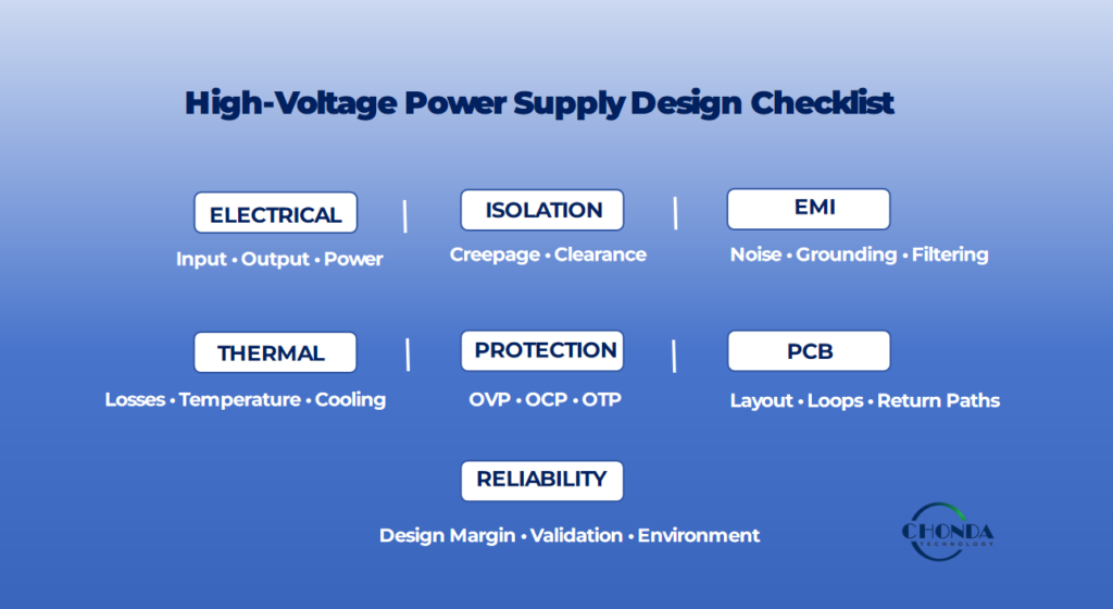
A high-voltage power supply should be considered ready for production only when these areas have been reviewed together and the design meets the requirements of the final application.
This checklist is intended as a practical engineering framework. Specific requirements and verification procedures should always be determined according to the actual equipment, applicable standards, and operating environment.
15. Standard vs Custom High-Voltage Power Supply Design
Once the electrical, isolation, thermal, EMI, protection, and mechanical requirements have been defined, engineers must decide whether a standard power supply is sufficient or whether a customized solution is more appropriate.
A standard power module can significantly reduce development time when its electrical and mechanical specifications already match the application.
However, some industrial systems have requirements that cannot be met effectively by an off-the-shelf product. In these cases, customization may provide a more practical way to achieve the required performance and system integration.
15.1 When Is a Standard Power Module Appropriate?
A standard power module may be suitable when the main application requirements already fall within an existing product specification.
Typical conditions include:
- Input voltage is within the available operating range.
- Output voltage and current match the application.
- Required power is within the specified range.
- Isolation performance is sufficient.
- Mechanical dimensions are acceptable.
- Cooling conditions are compatible.
- Standard protection functions are adequate.
- Required operating and environmental conditions are supported.
Using a standard solution can offer several advantages:
- Shorter development time
- Lower engineering effort
- Faster prototype evaluation
- More predictable production planning
- Lower development cost
For many well-defined applications, a standard module can therefore provide the most efficient path from design to production.
15.2 When Is a Custom Power Solution More Appropriate?
Customization becomes more attractive when one or more important system requirements fall outside the range of standard products.
Typical examples include:
- Unusual input-voltage ranges
- Special output-voltage or current requirements
- Non-standard power ratings
- Special isolation requirements
- Restricted PCB dimensions
- Unusual mounting arrangements
- Specific connector configurations
- Demanding thermal conditions
- Application-specific protection functions
- Special EMI requirements
In these situations, modifying the overall equipment around an unsuitable standard power supply may create unnecessary complexity.
A customized power solution can instead be designed around the actual system constraints.
15.3 Customization Does Not Always Mean a Completely New Design
Customization does not necessarily require developing a completely new power supply from the beginning.
Depending on the application, customization may involve:
- Adjusting input-voltage range
- Modifying output voltage or current
- Changing component ratings
- Revising the PCB layout
- Changing mechanical dimensions
- Modifying connectors
- Adjusting isolation construction
- Optimizing thermal performance
- Adding or modifying protection functions
A modified standard platform can therefore be a practical middle ground between a fully standard product and a completely new architecture.
15.4 Standard vs Custom: A Practical Comparison
| Consideration | Standard Power Module | Custom Power Solution |
|---|---|---|
| Development time | Usually shorter | Usually longer |
| Initial engineering effort | Lower | Higher |
| Customization flexibility | Limited | High |
| Input/output requirements | Within existing range | Can be application-specific |
| Mechanical design | Fixed or limited options | Can be optimized |
| Isolation requirements | Based on existing design | Can be tailored |
| Protection | Standard functions | Can be application-specific |
| Thermal design | Based on existing construction | Can be optimized |
| EMI optimization | Existing design characteristics | Can be adapted to system needs |
| Best suited for | Well-defined applications | Specialized or demanding applications |
The best choice depends on the total development and system requirements rather than simply comparing unit price.
15.5 When Customization Can Reduce System Complexity
At first, a customized power supply may appear to require more engineering work and a higher development investment.
However, customization can sometimes reduce complexity elsewhere in the system.
For example, a power module designed around the actual equipment may:
- Reduce additional conversion stages
- Simplify mechanical integration
- Reduce unnecessary external components
- Improve thermal integration
- Simplify wiring
- Better match the system’s isolation requirements
The important question is therefore not only:
How much does the power supply cost?
but also:
How much complexity does the power supply create or remove from the complete system?
15.6 Standard, Modified, or Fully Custom?
A practical development strategy can use three levels:
Standard
Use an existing product when the system requirements already match the available specifications.
Modified Standard
Adjust an existing platform when only a limited number of electrical or mechanical parameters need to be changed.
Fully Custom
Develop a dedicated solution when the application requires a fundamentally different electrical architecture, mechanical design, isolation system, or performance profile.
This approach allows engineers to choose the appropriate level of customization without automatically assuming that every special requirement requires a completely new design.
15.7 Working with a Power-Supply Supplier
When a custom solution is required, clear technical communication can significantly reduce development time.
Engineers should provide as much information as practical, including:
- Input voltage and operating range
- Output voltage and current
- Required power
- Isolation requirements
- Operating temperature
- Mechanical dimensions
- Cooling conditions
- Protection requirements
- EMI requirements
- Expected annual volume
- Development schedule
This allows the supplier’s engineering team to evaluate the application more accurately and determine whether a standard product, modified platform, or custom design is the most appropriate approach.
15.8 CHONDA’s Approach to Standard and Custom Solutions
CHONDA supports both standard power modules and application-specific power solutions for industrial applications.
Our product range includes:
- AC-DC power modules
- Isolated DC-DC power modules
- High-voltage DC-DC converters
- Toroidal transformers
- Audio and isolation transformers
- Customized power solutions
For standard applications, an existing product can provide a practical route to prototype testing and production.
For applications with unusual electrical, mechanical, isolation, thermal, or environmental requirements, CHONDA can work with customers to evaluate the requirements and develop a suitable customized solution.
The objective is not to customize every project, but to select the simplest and most reliable solution that satisfies the actual application requirements.
Conclusion
The decision between a standard and custom high-voltage power supply should be based on the complete system requirements.
A standard module is often the best choice when the application fits an existing specification and rapid development is important.
A modified or fully customized solution becomes more attractive when electrical, mechanical, isolation, thermal, EMI, or application requirements fall outside the range of standard products.
The most effective approach is to first define the system requirements, then determine whether a standard product is sufficient before investing in customization.
For industrial power applications, the right solution is not necessarily the most customized one. It is the solution that provides the required performance, reliability, integration, and long-term suitability with an appropriate level of engineering complexity.
Related Articles
What Is a High Voltage DC-DC Converter?
High Voltage DC-DC Converter Isolation Design: Principles and Applications
High Voltage DC-DC Converter EMI Design Considerations
High Voltage DC-DC Converter Thermal Management
High Voltage DC-DC Converter Protection Features
High Voltage DC-DC Converter PCB Design Considerations
Isolation Transformer vs Isolated DC-DC Converter: Which Is Right for Your Application?