We help the world since 2012

How to Improve High Voltage DC-DC Converter Reliability
High voltage DC-DC converters are often required to operate continuously under demanding electrical, thermal, and environmental conditions.
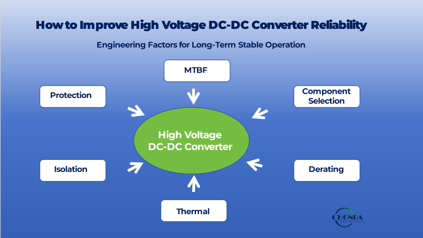
For industrial automation, railway systems, telecommunications, renewable energy, battery energy storage, and other critical applications, converter reliability is not determined by a single component or specification. It is the result of coordinated decisions involving component selection, electrical derating, thermal management, isolation design, protection functions, control strategy, PCB layout, and operating conditions.
A reliable high voltage DC-DC converter should maintain stable operation throughout its specified operating range while controlling component stress, temperature rise, electrical transients, and insulation stress.
This is why reliability should be considered from the earliest stages of converter design rather than treated as a final validation step.
1. What Determines High Voltage DC-DC Converter Reliability?
Converter reliability is influenced by several interacting engineering factors.
The most important factors typically include:
- Component selection
- Electrical and thermal derating
- Power loss and heat generation
- Operating temperature
- Input voltage variation
- Switching stress
- Isolation system
- Protection design
- PCB and mechanical design
- Manufacturing quality
- Application environment
These factors are interconnected.
For example, higher component temperature can accelerate aging, while excessive electrical stress can increase the probability of component failure. Similarly, insufficient isolation margin can create long-term reliability risks even when the converter operates normally during initial testing.
Therefore, reliability should be evaluated as a system-level design objective rather than as a single product specification.
2. MTBF and High Voltage DC-DC Converter Reliability
MTBF, or Mean Time Between Failures, is commonly used as a reliability indicator for electronic equipment.
MTBF describes the statistical relationship between failures within a defined population and operating conditions. It should not be interpreted as a guaranteed operating lifetime for an individual converter.
For example, a converter specified with a high MTBF value does not mean that every unit will operate for exactly that number of hours before failure.
Actual reliability depends on factors such as:
- Component quality
- Operating temperature
- Electrical stress
- Load conditions
- Input voltage
- Switching conditions
- Environmental conditions
- Manufacturing quality
- Cooling and thermal management
MTBF calculations are therefore most meaningful when the underlying assumptions and operating conditions are clearly defined.
Why MTBF Alone Is Not Enough
A high MTBF value should not replace engineering evaluation of the actual application.
Engineers should also examine:
- Maximum component temperature
- Voltage and current stress
- Capacitor operating conditions
- Transformer temperature
- Isolation requirements
- Protection thresholds
- Environmental conditions
- Expected load profile
A converter with an appropriate reliability design should be evaluated against the actual operating environment rather than selected only by comparing MTBF numbers.
3. Component Selection for Converter Reliability
Component selection is one of the foundations of high voltage DC-DC converter reliability.
High voltage operation can place additional electrical stress on switching devices, capacitors, transformers, insulation materials, connectors, and other components.
Engineers should consider both the electrical rating and the expected operating stress of each component.
Important considerations include:
- Voltage rating
- Current rating
- Temperature rating
- Switching capability
- Surge capability
- Insulation performance
- Component lifetime
- Manufacturer quality
- Application history
A component should not simply be selected because its nominal rating appears higher than the normal operating voltage.
The expected transient conditions, temperature, switching stress, and long-term aging mechanisms should also be considered.
High Voltage Component Margin
For high voltage converters, adequate voltage margin is particularly important.
If a component operates very close to its maximum rated voltage, relatively small transients or operating variations may significantly reduce the available design margin.
A more robust design considers:
Normal operating voltage → transient voltage → component rating → required safety margin
This approach helps reduce electrical stress and improve long-term reliability.
4. Electrical Derating and Reliability
Derating means operating a component below its maximum specified electrical or thermal capability.
Derating can reduce component stress and provide additional margin against variations, transients, aging, and environmental changes.
Typical derating considerations include:
- Voltage derating
- Current derating
- Power derating
- Temperature derating
- Frequency-related stress
- Capacitor ripple-current derating
For example, a switching device rated for a certain maximum voltage should not automatically be operated continuously at that maximum value simply because the rating permits it.
The appropriate derating level depends on the converter topology, operating conditions, component technology, transient environment, and reliability target.
Why Derating Matters in High Voltage Applications
High voltage systems can experience operating conditions that are different from their nominal steady-state conditions.
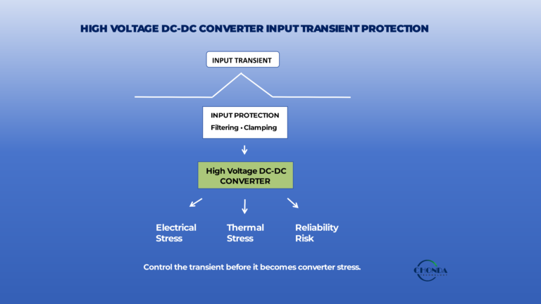
Input voltage fluctuations, switching overshoot, startup events, load changes, and external transients can temporarily increase component stress.
Adequate derating provides additional design margin against these conditions.
However, excessive derating can also increase component cost, size, and losses.
Therefore, effective derating is an engineering optimization rather than simply choosing the largest available component.
5. Thermal Management and Converter Reliability
Temperature is one of the most important factors affecting the long-term reliability of electronic components.
Power losses inside a DC-DC converter are ultimately converted into heat.
Major sources of heat may include:
- Switching losses
- Conduction losses
- Transformer losses
- Rectification losses
- Magnetic losses
- Capacitor losses
- Control and auxiliary circuit losses
As temperature increases, component stress and aging can also increase.
Thermal design should therefore consider the complete converter rather than only the main switching device.
Identifying the Worst-Case Thermal Condition
The highest thermal stress does not necessarily occur at the highest input voltage.
The actual worst-case operating point depends on:
- Converter topology
- Input voltage
- Output power
- Load condition
- Switching frequency
- Component losses
- Efficiency profile
- Ambient temperature
- Cooling conditions
This means engineers should evaluate thermal performance across the expected operating range rather than testing only one nominal operating point.
Thermal Derating
A converter may need to reduce its allowable output power as ambient temperature increases.
This is commonly represented through a thermal derating curve.
For example:
Higher ambient temperature → higher component temperature → lower allowable load → required derating
Good thermal design should ensure that critical components remain within their specified temperature limits under the expected worst-case operating conditions.
6. Isolation and High Voltage Converter Reliability
Isolation is another critical part of high voltage DC-DC converter reliability.
An isolation barrier separates electrical domains and helps prevent hazardous voltage from propagating into circuits, interfaces, or equipment that must remain electrically separated.
Important isolation considerations include:
- Isolation voltage
- Creepage distance
- Clearance distance
- Insulation system
- Transformer construction
- PCB layout
- Pollution environment
- Working voltage
- Transient voltage
- Insulation aging
Isolation should therefore be evaluated not only by the headline isolation-test voltage.
The actual working voltage, transient environment, insulation construction, and applicable safety requirements must also be considered.
Isolation Reliability Over Time
An isolation system must maintain its required performance throughout the expected operating life.
Repeated electrical stress, temperature cycling, humidity, contamination, mechanical stress, and material aging can affect insulation performance.
For this reason, robust isolation design requires appropriate insulation materials, spacing, transformer construction, PCB layout, and production controls.
7. Protection Design and Converter Reliability
Protection functions help prevent abnormal operating conditions from developing into permanent component damage.
Depending on the converter architecture and application, protection may include:
- Input overvoltage protection
- Input undervoltage protection
- Overcurrent protection
- Short-circuit protection
- Overtemperature protection
- Surge protection
- Reverse-polarity protection
- Output overvoltage protection
Protection design should be coordinated with the normal operating range of the converter.
For example, an undervoltage threshold should distinguish between a normal low-input operating condition and an abnormal supply condition.
Similarly, overvoltage protection should account for both normal input variation and transient events.
Protection Is Not a Substitute for Derating
Protection circuits are important, but they should not be considered a replacement for proper component selection and derating.
A robust converter uses multiple layers of protection:
Appropriate component rating → Derating → Thermal management → Protection → Fault response
This layered approach can reduce the probability that an abnormal event will cause permanent damage.
8. Reliability Under Real Application Conditions
A converter that performs well in a laboratory environment may experience different stresses in a real system.
Actual application conditions may include:
- Input voltage variation
- Rapid load changes
- Startup and shutdown cycles
- High ambient temperature
- Low ambient temperature
- Vibration
- Humidity
- Dust or contamination
- Electrical transients
- Long operating hours
Therefore, converter reliability should be evaluated using the expected application profile.
For demanding applications, engineers should define the operating envelope before selecting the converter.
This includes:
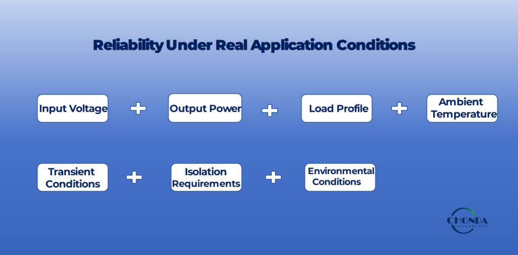
The converter should then be evaluated against this complete set of requirements.
9. Reliability Is a System-Level Design Objective
High voltage DC-DC converter reliability cannot be created by increasing one specification.
A converter with a higher voltage rating may still have thermal limitations. A converter with excellent efficiency may still require stronger isolation. A converter with a high MTBF estimate may still be unsuitable for an application with severe transients or high ambient temperature.
Reliable design therefore requires a balanced approach.
The key relationships can be summarized as:
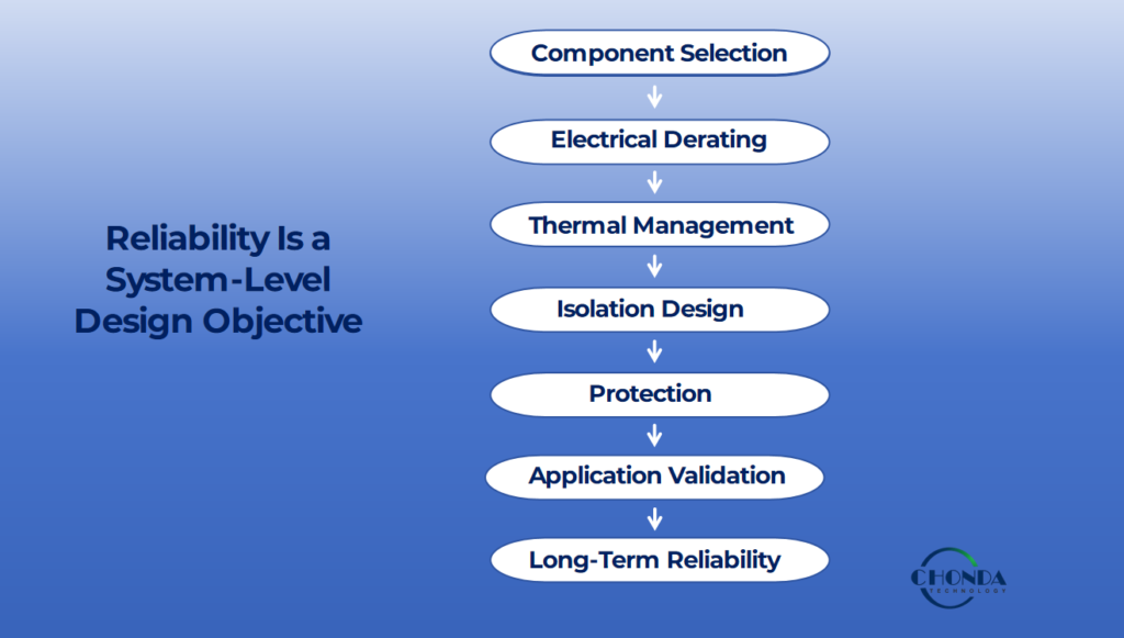
Engineers should evaluate these factors together when designing or selecting a high voltage DC-DC converter.
10. How Engineers Should Evaluate Converter Reliability
Before selecting a high voltage DC-DC converter, engineers should ask:
- What is the actual input-voltage range?
- What transient voltages can occur?
- What is the required output power?
- What is the expected load profile?
- What is the maximum ambient temperature?
- What thermal derating is required?
- What isolation voltage is required?
- What protection functions are necessary?
- What environmental conditions will the converter experience?
- What reliability target is required for the application?
This approach is more useful than evaluating reliability from a single number such as MTBF.
11. CHONDA High Voltage DC-DC Converter Reliability Approach
CHONDA develops isolated DC-DC converter solutions for applications where electrical reliability, isolation, thermal performance, and long-term operating stability are important.
Depending on the application, converter design can involve:
- Defined input-voltage ranges
- Isolated power conversion
- Thermal optimization
- Protection functions
- Component selection
- Electrical derating
- Custom mechanical integration
- OEM requirements
The appropriate converter should be selected according to the actual electrical and environmental requirements of the target system.
PHV Series
CHONDA’s PHV series provides a standard solution path for high-voltage DC-DC conversion applications requiring defined input and output specifications.
For applications that fall outside the standard product range, engineering requirements can be reviewed for a customized solution.
Custom and OEM Reliability Requirements
Some projects require specific:
- Input-voltage ranges
- Output voltage and current
- Power levels
- Isolation requirements
- Protection thresholds
- Mechanical dimensions
- Pin definitions
- Cooling conditions
- Annual production volume
For these applications, reliability considerations can be incorporated into the converter design from the beginning rather than added after prototype development.
12. Frequently Asked Questions
Q1. What is MTBF in a DC-DC converter?
MTBF, or Mean Time Between Failures, is a statistical reliability indicator describing the expected time between failures within a defined population and under specified operating conditions. It should not be interpreted as a guaranteed lifetime for an individual converter.
Q2. Does a higher MTBF always mean a more reliable converter?
No. MTBF is only one reliability indicator. Actual converter reliability also depends on component stress, temperature, derating, isolation, protection, environmental conditions, and application requirements.
Q3. Why is component derating important?
Derating reduces the electrical or thermal stress placed on components and provides additional design margin against variations, transients, aging, and abnormal operating conditions.
Q4. How does temperature affect DC-DC converter reliability?
Higher operating temperature can increase component stress and accelerate aging mechanisms. Thermal design and appropriate derating are therefore important for long-term reliability.
Q5. Does isolation affect converter reliability?
Yes. The isolation system must maintain its required electrical separation under normal operating voltage, transient conditions, temperature, environmental stress, and expected service life.
Q6. What protection functions are important for high voltage DC-DC converters?
Depending on the application, important protection functions may include overvoltage, undervoltage, overcurrent, short circuit, overtemperature, surge, reverse polarity, and output overvoltage protection.
Q7. Can a high efficiency converter still have reliability problems?
Yes. High efficiency reduces power loss, but reliability also depends on component selection, electrical stress, thermal conditions, isolation, protection, and application environment.
Q8. How should engineers evaluate the reliability of a high voltage DC-DC converter?
Engineers should evaluate the complete operating envelope, including input voltage, transient conditions, output power, load profile, ambient temperature, thermal performance, isolation, protection, environmental conditions, and reliability targets.
13. Conclusion
High voltage DC-DC converter reliability is the result of coordinated engineering decisions rather than a single specification.
Component selection, electrical derating, thermal management, isolation, protection, and application validation all contribute to long-term converter performance.
MTBF can provide a useful statistical reliability indicator, but it should be evaluated together with the actual operating conditions and design margins of the application.
For demanding power systems, reliability should be considered from the earliest stages of converter selection and design.
CHONDA provides standard and customized isolated DC-DC converter solutions for industrial, railway, telecommunications, renewable-energy, and other demanding applications where defined electrical, thermal, isolation, and protection requirements must be addressed.
📚 Continue Reading
For a broader discussion of the engineering factors involved in high voltage converter design:
→ High Voltage DC-DC Converter Design Challenges
→ Wide Input DC-DC Converter Design Guide
Related Articles
→ Railway DC-DC Converter
→ Industrial Automation DC-DC Converter
→ Telecommunication DC-DC Converter
→ PV Monitoring Power Supply
→ Battery Energy Storage (BESS)