We help the world since 2012

High Voltage DC-to-Low-Voltage DC Converter Design: Architecture and Selection
Many industrial systems operate from a high-voltage DC source while their control, monitoring, communication, and auxiliary electronics require much lower DC voltages.
This creates a common power-conversion requirement:
High-Voltage DC → Low-Voltage DC
A typical system may start with a high-voltage DC bus and then use a DC-DC converter to generate a regulated low-voltage output such as 24V, 12V, or another application-specific voltage.
A simplified architecture can be represented as:
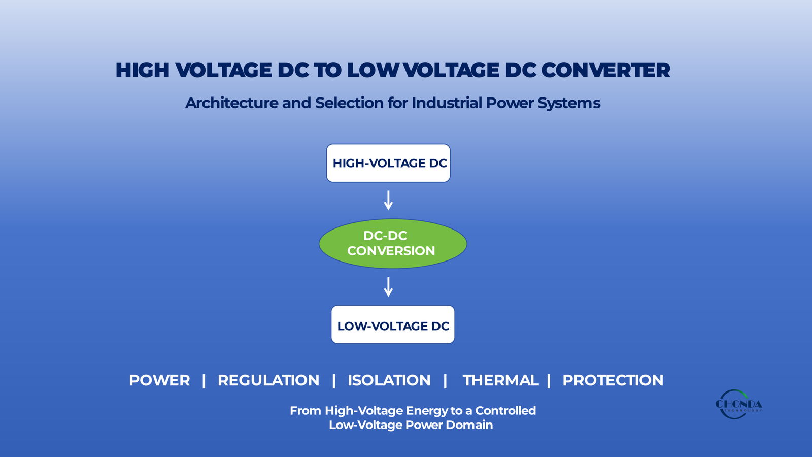
High-Voltage DC Bus → DC-DC Converter → Low-Voltage DC Load
Although the basic function appears straightforward, the design becomes more complicated as the input voltage, output power, isolation requirements, regulation accuracy, thermal conditions, and system safety requirements become more demanding.
For example, a converter supplied from a high-voltage DC bus may need to operate across a wide input range while delivering a stable low-voltage output to sensitive electronics.
At the same time, the designer may need to consider:
- Input-voltage range
- Output voltage and power
- Galvanic isolation
- Efficiency
- Thermal performance
- Switching frequency
- EMI
- Protection
- Creepage and clearance
- Mechanical integration
The architecture chosen for the high-voltage-to-low-voltage conversion stage can therefore have a significant influence on the rest of the equipment.
A centralized converter may be appropriate for one system, while another may benefit from several dedicated or isolated DC-DC modules serving different power domains.
This guide examines the main architecture options for converting high-voltage DC to low-voltage DC, explains the key selection criteria, and shows how engineers can match the converter structure to the actual requirements of industrial equipment.
The objective is not simply to find a converter that can reduce voltage.
It is to select a high-voltage DC-to-low-voltage DC architecture that provides the required output power, regulation, isolation, thermal performance, and reliability for the complete application.
1. What Is the Role of HV-to-LV DC-DC Conversion?
In many industrial power systems, the primary power source operates at a voltage level that is significantly higher than the voltage required by the electronic circuits that control, monitor, or communicate within the equipment.
The role of an HV-to-LV DC-DC converter is to bridge these two voltage domains.
A simplified power architecture can be represented as:
High-Voltage DC Bus → HV-to-LV DC-DC Converter → Low-Voltage Power Domain → Electronic Loads
The converter therefore acts as more than a device that simply reduces voltage.
It establishes the electrical conditions required by the low-voltage side while managing the difference between the high-voltage source and the requirements of the downstream electronics.
1.1 Creating a Usable Low-Voltage Power Domain
Industrial equipment may operate from a high-voltage DC bus while individual electronic subsystems require much lower voltages.
For example, a system may use a high-voltage DC source while its control electronics require 24V and communication or auxiliary circuits require 12V or another regulated voltage.
The HV-to-LV converter creates a controlled low-voltage power domain from the high-voltage source.
This allows the downstream electronics to operate within the voltage range for which they were designed.
1.2 Connecting the Main DC Bus to Sensitive Electronics
The high-voltage bus may be suitable for energy distribution, but it is generally not an appropriate direct supply for low-voltage control and monitoring circuits.
The HV-to-LV conversion stage therefore forms an important boundary between the main power system and the electronic subsystems.
For example:
High-Voltage DC Bus → HV-to-LV Converter → 24V Control System
or:
High-Voltage DC Bus → HV-to-LV Converter → Low-Voltage Monitoring Electronics
The converter must maintain the required low-voltage output even when the high-voltage input changes within its specified operating range.
1.3 Providing a Stable Supply for Downstream Electronics
Low-voltage electronic systems often have relatively tight requirements for supply voltage, ripple, and transient response.
A high-voltage source may experience a much wider operating range than these circuits can tolerate directly.
The HV-to-LV converter therefore provides the regulation required to create a usable low-voltage supply.
For example:
HV Input Variation → DC-DC Conversion → Regulated Low-Voltage Output
The quality of this conversion can directly influence the behavior of controllers, sensors, communication interfaces, and other electronic loads.
1.4 Isolation Can Define the Electrical Boundary
Depending on the application, the HV-to-LV converter may also provide galvanic isolation between the high-voltage source and the low-voltage domain.
This can be important when the low-voltage electronics require a defined electrical boundary from the high-voltage system.
For example:
High-Voltage DC → Isolated DC-DC → 24V Control
creates a different system architecture from:
High-Voltage DC → Non-Isolated DC-DC → 24V Control
The isolation requirement is therefore not simply a converter specification. It can determine how the low-voltage domain relates to the rest of the equipment.
1.5 One High-Voltage Source Can Support Multiple Low-Voltage Domains
A complex industrial system may need several low-voltage power domains.
For example:
High-Voltage DC Bus
↓
24V Control
12V Communication
Isolated Monitoring Supply
Auxiliary Power
These outputs can be provided by separate conversion stages or by a modular architecture depending on the system requirements.
The important point is that the HV-to-LV conversion stage defines how the high-voltage energy source is distributed into the different low-voltage functions of the equipment.
1.6 The Converter Becomes Part of the System Architecture
Once the high-voltage input and low-voltage loads have been defined, the converter influences several downstream design decisions.
These may include:
- Power-domain structure
- Isolation boundaries
- Output regulation
- Thermal design
- Protection
- EMI
- Mechanical integration
For this reason, the converter should be selected according to the requirements of the complete system rather than only by matching an input and output voltage.
1.7 The Same Voltage Conversion Can Serve Very Different Systems
An HV-to-LV converter may be used in different industrial environments, but the required architecture can vary substantially.
For example, a monitoring system may prioritize isolation and low noise.
A control system may prioritize output regulation and transient response.
A compact embedded system may place greater importance on size and power density.
The conversion ratio alone therefore does not define the correct solution.
The final architecture depends on what the low-voltage domain needs from the high-voltage power source.
1.8 The Practical Role of HV-to-LV Conversion
The role of an HV-to-LV DC-DC converter can therefore be summarized as:
High-Voltage Energy Source
↓
Controlled Voltage Conversion
↓
Low-Voltage Power Domain
↓
Reliable Electronic Loads
The converter creates the electrical bridge between the main high-voltage power architecture and the low-voltage electronics that perform the actual control, monitoring, communication, and auxiliary functions.
This is why the design or selection of an HV-to-LV converter should begin with the requirements of both sides of the conversion boundary: the high-voltage source and the low-voltage loads.
The next step is to define the actual high-voltage input conditions that the converter must tolerate, including the nominal voltage, operating range, transients, and available input power.
2. Define the High-Voltage Input Requirements
Before selecting a high-voltage DC-to-low-voltage DC converter, engineers should first define the electrical conditions on the high-voltage side.
The converter may be described by a nominal input voltage, but the actual operating environment is usually more complicated.
The high-voltage source may vary during normal operation, experience short-duration transients, and provide different amounts of available power depending on the system condition.
For this reason, the input requirement should be treated as a complete electrical envelope rather than a single voltage value.
2.1 Nominal High-Voltage Input
The first parameter is the nominal voltage of the DC source.
For example, an industrial system may operate from a defined high-voltage DC bus supplied by a battery system, PV source, BESS, rectified AC source, or another DC power architecture.
The nominal value provides the starting point for converter selection, but it does not define the complete operating condition.
The converter must also tolerate the actual voltage variation that can occur around that nominal value.
2.2 Define the Full Input-Voltage Range
The most important input parameter is often the minimum and maximum operating voltage.
For example, a converter may be required to operate from:
300–1000VDC
rather than from one fixed 600VDC input.
This range directly affects the semiconductor voltage stress, switching conditions, magnetic design, control strategy, and thermal behavior of the converter.
The downstream output requirement may remain unchanged while the input voltage changes significantly.
For example:
300VDC → 24VDC
and:
1000VDC → 24VDC
require very different operating conditions even though the final output voltage is identical.
A wide input range can therefore make the converter architecture more demanding.
2.3 Minimum Input Voltage Can Be a Critical Condition
The minimum input voltage should not be treated as a secondary specification.
At a lower input voltage, the converter may need to draw more input current to deliver the same output power.
For example, if the output power remains constant:
Lower Input Voltage → Higher Input Current
Higher input current can affect:
- Semiconductor conduction loss
- Transformer and inductor winding loss
- PCB copper loss
- Connector and wiring loss
- Thermal load
This means that the minimum input voltage can become one of the important conditions for thermal and electrical verification.
2.4 Maximum Input Voltage Creates a Different Challenge
At the opposite extreme, a high input voltage can increase electrical stress on the power stage.
The converter may need to tolerate higher:
- Semiconductor voltage stress
- Insulation stress
- dv/dt
- Switching-node voltage
- Transformer insulation requirements
The maximum input condition should therefore be evaluated independently from the minimum input condition.
The two extremes often create different design limitations.
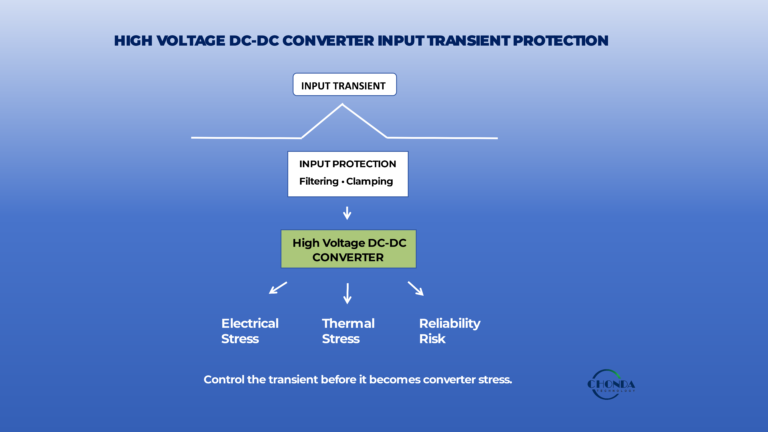
2.5 Input Transients
The converter also needs to tolerate short-duration voltage events that fall outside the normal operating range.
These may come from:
- Source switching
- Battery-system events
- Industrial load switching
- DC-bus disturbances
- Upstream converter behavior
- Fault or recovery events
A converter that operates reliably within the normal input range may still experience excessive stress during a transient event.
The input specification should therefore distinguish between:
Normal Operating Range
and:
Transient / Abnormal Conditions
The required protection and control response can then be designed accordingly.
2.6 Startup and Shutdown Conditions
The input voltage seen by the converter during startup may be different from the steady-state condition.
For example, a high-voltage DC bus may rise gradually, overshoot briefly, or interact with the input capacitance of the converter.
Likewise, when the source is removed, the input may decay through the converter’s internal and external circuits rather than disappearing instantaneously.
Engineers should therefore consider:
Startup → Normal Operation → Transient → Shutdown
as part of the input-voltage definition.
This is especially important for systems that start and stop frequently or operate with controlled DC-bus sequencing.
2.7 Available Input Power
The input source must also be capable of providing the required power.
A converter may have a suitable voltage range but still be inappropriate if the source cannot supply the required power during normal or peak operation.
For example, a system may require:
80W Continuous Output
with:
100W Peak Output
The high-voltage source must provide sufficient power for the converter to meet these requirements while allowing for conversion losses.
The practical relationship is:
Input Power ≥ Output Power / Efficiency
The exact margin depends on the operating conditions and system requirements.
2.8 Continuous and Peak Input Conditions
Power availability should also be considered over time.
A converter may operate continuously at one power level while occasionally experiencing a short-duration peak.
For example:
Continuous Power → 80W
Peak Power → 100W for a defined duration
The source, converter, thermal system, and protection strategy should all be able to accommodate the intended peak condition.
A short peak does not necessarily require the same continuous thermal capability as the steady-state load, but it still needs to be verified.
2.9 Source Impedance Can Affect Converter Behavior
The high-voltage source is not an ideal voltage generator.
Battery systems, long cables, DC buses, upstream converters, and distribution structures all have some source impedance.
A sudden increase in converter input current can therefore produce a temporary voltage change at the converter terminals.
This means that the actual input condition can depend on both:
Converter Power Demand
and:
Source Capability / Impedance
For high-power or wide-input applications, this interaction can become an important part of system-level design.
2.10 Define the Input Envelope Before Selecting the Converter
A useful input specification should therefore include:
Nominal Voltage
Minimum / Maximum Operating Voltage
Transient Voltage Conditions
Startup / Shutdown Behavior
Continuous Available Power
Peak Available Power
Source Characteristics
These parameters define the electrical environment that the HV-to-LV converter must tolerate.
Once the high-voltage side is clearly defined, the next step is to determine what the low-voltage side actually needs from the converter: output voltage, power, regulation, ripple, and transient performance.
3. Define the Low-Voltage Output Requirements
After the high-voltage input conditions have been defined, the next step is to understand what the low-voltage side actually requires from the converter.
The output specification should not be reduced to a single value such as 24VDC.
The downstream electronics may also require a defined continuous power level, short-duration peak power, stable regulation, low ripple, and predictable behavior during load changes.
The low-voltage output requirement therefore needs to be defined as a complete operating envelope.
3.1 Output Voltage
The first requirement is the nominal output voltage.
Common industrial low-voltage domains may include:
24VDC
12VDC
5VDC
or another application-specific voltage.
The selected output voltage should match the requirements of the actual load rather than being chosen simply because it is a common industrial value.
For example, control electronics may require 24V while a communication or embedded circuit may require a lower regulated voltage.
3.2 Output-Voltage Regulation
The converter must maintain the required output voltage as the input voltage and load conditions change.
For example:
High-Voltage Input Variation → DC-DC Conversion → Regulated 24V Output
A converter that produces the correct voltage at one operating point may not provide adequate regulation when the high-voltage input changes across its full range.
The regulation requirement should therefore be evaluated together with:
- Minimum input voltage
- Maximum input voltage
- Load range
- Temperature
- Transient conditions
The acceptable output-voltage variation depends on the sensitivity of the downstream electronics.
3.3 Continuous Output Power
The continuous power requirement defines how much output power the converter must deliver under normal operation.
For example, a monitoring system may require:
80W Continuous Output
while another control system may require only 20W.
The converter’s continuous rating should be selected based on the actual load profile rather than simply using the highest theoretical load value without considering how the equipment operates.
Continuous power is particularly important for thermal design because the associated losses must be removed for as long as the equipment remains in operation.
3.4 Peak Output Power
Some loads require substantially more power for short periods.
For example:
80W Continuous → 100W Peak
The converter may therefore need to provide additional power for a defined duration without entering an unwanted protection state or exceeding its thermal or electrical limits.
Peak power should be defined together with:
- Peak magnitude
- Peak duration
- Frequency of occurrence
- Recovery time
- Load conditions
A converter that can deliver 100W for one second is not necessarily equivalent to one that can deliver 100W continuously.
The peak requirement must therefore be clearly defined.
3.5 Load Profile Matters
The output load may change significantly during normal equipment operation.
A control system may spend most of its time at relatively low power and only occasionally reach its maximum demand.
A monitoring or communication system may have a different load pattern.
For this reason, engineers should consider:
Minimum Load
Typical Load
Maximum Continuous Load
Peak Load
The converter should then be evaluated across the complete expected load profile.
This can also influence efficiency and thermal behavior.
3.6 Output Ripple
Low-voltage electronic circuits can be sensitive to ripple and high-frequency noise on their supply rails.
The acceptable ripple depends on the application.
A digital control circuit may tolerate a different ripple level from an analog measurement circuit or a sensitive communication interface.
The converter’s output specification should therefore define an appropriate ripple requirement rather than assuming that any regulated DC voltage is sufficient.
Output ripple can be influenced by:
- Converter topology
- Switching frequency
- Output inductance
- Output capacitance
- Load condition
- Control strategy
3.7 Load Transients
A low-voltage load may change rapidly.
For example, a controller, communication circuit, or actuator interface may suddenly increase its current demand.
The converter should respond without allowing the output voltage to move outside the acceptable range.
A simplified event can be viewed as:
Load Increase → Output Current Demand ↑ → Output Voltage Disturbance → Converter Response
The quality of this transient response becomes more important when the downstream electronics have tight voltage requirements.
3.8 Multiple Low-Voltage Outputs
Some industrial systems require more than one low-voltage rail.
For example:
24V Control
12V Communication
5V Embedded Electronics
In this situation, engineers need to decide whether to use:
- One converter with multiple outputs
- Multiple dedicated DC-DC modules
- One main converter followed by additional low-voltage conversion stages
This is an architectural decision rather than simply an output-voltage specification.
The correct choice depends on power levels, isolation, regulation requirements, load interaction, and system flexibility.
3.9 Output Isolation Requirements
The low-voltage side may also require a specific relationship with the high-voltage source or with other low-voltage domains.
For example, a monitoring circuit may need an isolated 24V output while a control circuit may be able to use a shared reference.
This requirement directly affects the converter architecture.
A simplified comparison is:
HV DC → Non-Isolated DC-DC → 24V
versus:
HV DC → Isolated DC-DC → 24V
The voltage conversion may be identical in both cases, but the electrical relationship between the two domains is fundamentally different.
The isolation decision is therefore part of the output requirement and should be defined before the converter topology is finalized.
3.10 Low-Voltage Output Requirements Define the Real Converter Job
A complete output specification should ideally include:
Output Voltage
Output Voltage Tolerance
Continuous Power
Peak Power and Duration
Minimum / Typical / Maximum Load
Output Ripple
Load-Transient Requirement
Number of Output Rails
Isolation Requirement
These parameters tell the engineer what the low-voltage side actually expects from the converter.
Once both sides of the conversion boundary are clearly defined—
High-Voltage Input Environment
and
Low-Voltage Output Requirements
—the next architectural question becomes critical:
Does the low-voltage domain need galvanic isolation from the high-voltage source?
4. Is Galvanic Isolation Required?
One of the most important architectural decisions in a high-voltage DC-to-low-voltage DC converter is whether the low-voltage output must be galvanically isolated from the high-voltage source.
The voltage-conversion function may appear similar in both cases, but the electrical relationship between the two sides is fundamentally different.
A simplified comparison is:
High-Voltage DC → Non-Isolated DC-DC → Low-Voltage DC
versus:
High-Voltage DC → Isolated DC-DC → Low-Voltage DC
The correct choice depends on the safety, grounding, control, measurement, and system-integration requirements of the equipment.
4.1 What Galvanic Isolation Changes
In an isolated converter, there is no direct conductive path for DC current between the high-voltage input and low-voltage output.
Energy is transferred across an isolation barrier, typically through a transformer or another isolated power-conversion structure.
This creates a defined electrical boundary between the two domains.
For example:
High-Voltage DC → Isolated Power Stage → 24V Control
The 24V domain can therefore have a different electrical reference from the high-voltage source.
This can be important when the low-voltage electronics need to remain separated from the high-voltage system.
4.2 When Isolation Is Usually Valuable
Galvanic isolation may be appropriate when the low-voltage domain needs protection or electrical separation from the high-voltage source.
Typical situations include:
- Low-voltage circuits are accessible or connected to external interfaces.
- Measurement circuits require a separate electrical reference.
- Communication or control interfaces need isolation from the main power domain.
- The system architecture requires a defined safety boundary.
- Grounding requirements prevent the low-voltage output from sharing the high-voltage reference.
The exact requirement depends on the equipment, insulation system, and applicable safety standards.
4.3 Monitoring and Measurement Are Common Use Cases
Measurement electronics often create a strong reason to consider isolation.
For example, a high-voltage system may contain a monitoring circuit that measures electrical parameters while communicating with a lower-voltage controller.
A simplified arrangement could be:
High-Voltage DC → Isolated DC-DC → Monitoring Circuit
The isolated power domain can help establish a controlled electrical relationship between the measurement circuit and the rest of the system.
This does not automatically solve every noise or grounding issue, but it can provide an important architectural boundary.
4.4 Communication and Control Interfaces
Low-voltage communication or control electronics may also benefit from isolation when they connect to circuits with different grounding or common-mode conditions.
For example:
High-Voltage Power Domain
↓
Isolated DC-DC
↓
24V Control / Communication
The isolation barrier can reduce the need to create direct conductive paths between the two domains.
This can simplify some system-level grounding and interface decisions.
4.5 When Non-Isolated Conversion May Be Appropriate
Not every high-voltage-to-low-voltage application requires galvanic isolation.
A non-isolated converter may be appropriate when:
- Both sides can safely share a common electrical reference.
- The low-voltage circuit is not part of a required isolation boundary.
- The system benefits from a simpler power stage.
- Efficiency, size, or cost are important.
- The grounding architecture is already well defined.
For example:
HV DC Bus → Non-Isolated DC-DC → 24V Control
may be a practical architecture when the control domain is intentionally referenced to the same electrical system.
The key is that the shared reference must be intentional and compatible with the safety and system requirements.
4.6 Isolation Adds Design Requirements
Isolation can provide significant system benefits, but it also introduces additional engineering requirements.
The isolated converter must consider:
- Transformer or isolated power-transfer structure
- Insulation system
- Creepage
- Clearance
- Dielectric withstand
- Parasitic capacitance
- Common-mode coupling
- Thermal path across the isolation structure
Isolation can therefore affect not only safety but also efficiency, size, EMI, and mechanical construction.
4.7 Isolation Can Affect Thermal Design
A high-voltage isolation barrier may require insulating materials between a heat-generating component and a heat-spreading structure.
This can create a trade-off:
Electrical Isolation ↔ Thermal Transfer
For example, a semiconductor may need to remain electrically separated from a metal heat spreader while still transferring several watts of heat into it.
The thermal interface must therefore satisfy both requirements.
This is one reason isolation should be decided early in the architecture rather than added after the mechanical structure has already been defined.
4.8 Isolation Can Also Affect EMI Behavior
The absence of a direct conductive connection does not mean that high-frequency signals cannot cross an isolation barrier.
Parasitic capacitance can allow common-mode current to couple from one side to the other.
For example:
High-Voltage Switching Node → Parasitic Capacitance → Low-Voltage Side
This means an isolated converter can still require careful EMC consideration.
The isolation architecture therefore needs to be evaluated together with switching behavior and the surrounding physical structure.
4.9 How to Make the Decision
A practical decision sequence is:
Does the Low-Voltage Domain Need Electrical Separation?
↓
YES → Consider Isolated DC-DC Architecture
NO → Consider Non-Isolated Architecture
Then evaluate the consequences for:
Safety + Grounding + EMI + Thermal + Efficiency + Size + Cost
This prevents isolation from being treated as a simple checkbox.
4.10 Isolation Is an Architecture Decision, Not Just a Specification
The most useful question is therefore not:
“Does this converter have an isolation rating?”
It is:
“Does the complete low-voltage power domain need to be electrically separated from the high-voltage source, and where should that isolation boundary be located?”
The answer can change the converter topology, mechanical structure, PCB design, thermal path, grounding strategy, and EMC behavior.
For a deeper discussion of high-voltage isolation principles, creepage, clearance, and insulation architecture, see High Voltage DC-DC Converter Isolation Design: Principles and Applications.
For P57, the key design principle is:
Choose isolation because the system requires an electrical boundary, not simply because isolation is available as a converter feature.
5. Common HV-to-LV DC-DC Architectures
Once the high-voltage input, low-voltage output, and isolation requirements have been defined, the next step is to determine how the actual DC-DC conversion should be structured.
There is no single architecture that is ideal for every high-voltage-to-low-voltage application.
A simple non-isolated converter may be appropriate for one power domain, while another application may require an isolated stage or several dedicated converters serving different loads.
The right architecture depends on the relationship between the high-voltage source and the low-voltage functions that the equipment needs to support.
5.1 Simple Single-Stage HV-to-LV Conversion
The simplest architecture is:
High-Voltage DC → DC-DC Converter → Low-Voltage Load
This approach can be attractive when the system has one primary low-voltage output and relatively straightforward requirements.
For example:
600VDC → DC-DC → 24VDC
may be sufficient for a control system that does not require multiple isolated power domains.
The main advantage of this approach is simplicity.
There are fewer conversion stages, fewer interfaces, and generally less hardware to integrate.
However, the converter must handle the complete high-voltage input range while directly meeting the low-voltage output and thermal requirements.
5.2 Isolated HV-to-LV Conversion
When the low-voltage domain requires galvanic isolation, an isolated architecture can be used:
High-Voltage DC → Isolated DC-DC → Low-Voltage Load
This approach is common when the low-voltage side needs to be electrically separated from the high-voltage source.
The isolation barrier becomes part of the power-transfer structure, and the converter must account for insulation, creepage, clearance, parasitic capacitance, and thermal transfer across the isolated structure.
The additional isolation requirements generally increase design complexity, but they can provide an important system-level benefit where a defined electrical boundary is required.
5.3 Multiple Low-Voltage Outputs
Some industrial systems require more than one low-voltage rail.
For example:
High-Voltage DC → DC-DC → 24V Control
while also requiring:
12V Communication
or:
5V Embedded Electronics
One option is to use a converter with multiple outputs.
This can reduce the number of independent modules, but it also creates coupling between the output rails.
If one load changes significantly while another remains stable, the converter must maintain acceptable regulation across the complete output structure.
Multiple-output conversion can therefore be practical when the loads are closely related, but less attractive when each power domain has substantially different operating requirements.
5.4 Dedicated DC-DC Modules for Different Power Domains
Another approach is to use separate converters:
High-Voltage DC Bus
↓
DC-DC Module A → 24V Control
DC-DC Module B → Isolated Monitoring
DC-DC Module C → Communication / Auxiliary
This architecture can provide greater flexibility because each module can be selected around the actual requirements of its specific load.
It is particularly useful when the power domains have different:
- Output voltages
- Power levels
- Isolation requirements
- Operating profiles
- Noise sensitivities
The trade-off is the additional hardware, conversion losses, thermal load, and system integration effort.
5.5 High-Voltage Front End Followed by Low-Voltage Regulation
In some systems, the first conversion stage does not need to generate the final low-voltage rail directly.
Instead, the high-voltage source may first be converted into an intermediate DC level, followed by another regulation stage.
For example:
High-Voltage DC → Intermediate DC Bus → Low-Voltage DC
This can provide greater flexibility when the input voltage range is very wide or when several downstream power stages need to share the same intermediate bus.
However, every additional conversion stage introduces additional loss and complexity.
The architecture should therefore be justified by a real system requirement.
5.6 Modular HV-to-LV Architecture
For more complex systems, modularization may provide the best balance between flexibility and reuse.
A common structure is:
High-Voltage DC Bus
↓
Module A → Control
Module B → Monitoring
Module C → Communication
Module D → Auxiliary / Isolated Power
This approach can allow validated converter modules to be reused across different equipment configurations.
It can also make it easier to introduce new power domains without redesigning the entire high-voltage power stage.
However, the modules must still be evaluated together at the system level, particularly for bus interaction, thermal distribution, protection, and EMC.
5.7 Choosing Between Simplicity and Flexibility
The architecture decision often comes down to a practical trade-off.
A simple single-stage converter may provide:
Lower Component Count + Lower Integration Complexity
while a modular or multi-stage architecture may provide:
Greater Flexibility + Multiple Power Domains + Selective Isolation
Neither approach is universally better.
For a single low-voltage load, additional modularity may create unnecessary complexity.
For a system containing several different power domains, the additional architecture may provide enough value to justify the extra hardware.
5.8 Architecture Should Follow the Load Structure
One useful design principle is:
The number and structure of the power-conversion stages should reflect the structure of the loads.
If several loads have similar voltage, power, isolation, and operating requirements, they may be combined within one power domain.
If their requirements are substantially different, separating them into individual conversion stages may provide a cleaner solution.
This prevents the architecture from being determined simply by the number of available converter products.
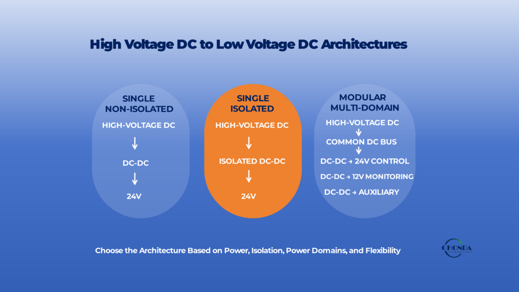
5.9 A Practical Architecture Comparison
The main options can be viewed conceptually as:
Single Non-Isolated
HV DC → DC-DC → LV
Best when simplicity is the priority.
Single Isolated
HV DC → Isolated DC-DC → LV
Best when a defined isolation boundary is required.
Multiple Outputs
HV DC → Multi-Output DC-DC → LV Rails
Best when several closely related low-voltage loads can share one conversion stage.
Modular
HV DC → Multiple DC-DC Modules → Different LV Domains
Best when the system contains several meaningfully different power domains or needs future flexibility.
The final decision should be based on the complete equipment requirements rather than on converter architecture alone.
5.10 The Architecture Determines the Next Design Decisions
Once the basic HV-to-LV architecture has been selected, the remaining design questions become more specific.
The engineer can then determine:
- How much efficiency is required
- Where the heat will be generated
- How the output should be regulated
- How transient loads should be handled
- What protection is required
- How the converter should be packaged
- Whether a standard or customized module is appropriate
The architecture is therefore the bridge between the system requirements and the detailed converter design.
The practical principle is:
Choose the simplest HV-to-LV architecture that satisfies the required voltage conversion, isolation, power-domain structure, flexibility, and reliability of the application.
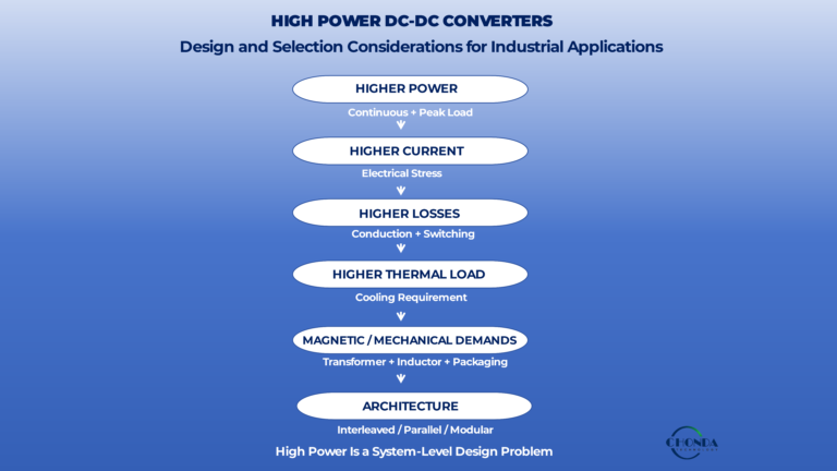
6. Efficiency and Thermal Trade-Offs
Efficiency and thermal performance are closely connected in high-voltage DC-to-low-voltage DC conversion.
The converter must reduce the high-voltage input to the required low-voltage output while keeping power losses within a level that the final equipment can accommodate.
This becomes particularly important when the converter operates continuously or when the available installation space is limited.
A useful starting relationship is:
Input Power → Conversion Losses → Heat
The higher the conversion loss, the more heat the converter must remove from its components and surrounding structure.
6.1 Conversion Losses Depend on the Operating Point
The efficiency of an HV-to-LV converter is not a fixed number.
It can change with:
- Input voltage
- Output power
- Load level
- Switching frequency
- Ambient temperature
- Operating mode
For example, a converter may operate efficiently near its normal load while showing different performance at very light load or near maximum output power.
The real application load profile should therefore be considered when evaluating converter efficiency.
6.2 Wide Input Voltage Can Increase the Design Challenge
A wide high-voltage input range can make efficiency optimization more difficult.
The converter may experience substantially different current and switching conditions between minimum and maximum input voltage.
At lower input voltage, more input current may be required to deliver the same output power.
At higher input voltage, semiconductor voltage stress and switching conditions may become more demanding.
The converter therefore needs to maintain acceptable performance across the complete input envelope rather than at one preferred operating point.
6.3 The Voltage Conversion Ratio Matters
Converting a very high DC voltage directly to a much lower output voltage can create a large conversion ratio.
For example:
800VDC → 24VDC
requires a substantially different power-conversion approach from:
200VDC → 24VDC
even though both systems produce the same output voltage.
A larger conversion ratio can influence:
- Converter topology
- Semiconductor selection
- Transformer turns ratio in isolated designs
- Switching conditions
- Control strategy
- Efficiency
This is one reason architecture should be considered before selecting an individual converter module.
6.4 Heat Is the Cost of Conversion Loss
Every watt of power lost inside the converter eventually becomes heat.
For example, if a converter delivers 100W at 95% efficiency, approximately 5W is dissipated internally.
That heat may be distributed across:
- Switching devices
- Transformer or inductors
- Rectification components
- Capacitors
- PCB structures
- Control circuits
The total heat may be manageable, but its physical distribution still matters.
A compact converter with concentrated losses can become thermally more demanding than a larger converter with similar total power loss.
6.5 Power Density Changes the Thermal Problem
Reducing converter size is often attractive in industrial equipment.
However, when the same output power is delivered from a smaller volume, the available space for heat spreading and cooling also becomes more limited.
This creates a practical relationship:
Higher Power Density → Greater Thermal Density
A smaller converter is therefore not necessarily easier to cool.
The architecture should provide enough thermal margin for continuous operation under the actual installation conditions.
6.6 Efficiency and Isolation Can Interact
An isolated HV-to-LV converter may provide an important electrical boundary, but the isolation structure can also introduce additional losses and thermal constraints.
For example, transformer losses can include:
- Core loss
- Winding loss
- High-frequency conductor loss
The insulation structure can also affect how heat moves from the internal loss sources toward the cooling environment.
The isolation requirement should therefore be evaluated together with efficiency and thermal performance rather than as a completely separate design issue.
6.7 Higher Switching Frequency Is Not Automatically Better
Increasing switching frequency can reduce the size of magnetic components and support higher power density.
However, it can also increase:
- Switching losses
- Gate-drive losses
- Magnetic losses
- EMI challenges
This creates a familiar engineering trade-off:
Higher Frequency → Smaller Magnetics
but potentially:
Higher Frequency → Higher Losses → Higher Thermal Load
The appropriate frequency depends on the complete converter architecture and application requirements.
6.8 The Low-Voltage Output Also Influences Thermal Behavior
The output current can become significant when the converter generates a relatively low output voltage.
For example, even moderate output power can require substantial current at 12V or 24V.
This can increase losses in:
- Output conductors
- Rectification devices
- Inductors
- Connectors
- PCB copper
The low-voltage side therefore needs to be evaluated as part of the overall thermal and efficiency design.
6.9 Continuous Operation Requires Thermal Margin
A converter that can deliver its rated power for a short period is not necessarily suitable for continuous industrial operation.
For continuous applications, engineers should consider:
Continuous Load + Ambient Temperature + Cooling Conditions + Component Temperature
The converter should retain sufficient thermal margin under the conditions in which the equipment is expected to operate for long periods.
This is particularly important for industrial monitoring systems, control electronics, and other equipment that may remain powered continuously.
6.10 Efficiency Should Be Evaluated at the System Level
The HV-to-LV converter may be only one stage in a larger power architecture.
For example:
AC → AC-DC → DC Bus → HV-to-LV DC-DC → Load
or:
Battery / PV → HV-to-LV DC-DC → Low-Voltage Electronics
The overall system efficiency depends on all active conversion stages.
A slightly lower-efficiency HV-to-LV stage may still be the better system solution if it provides the required isolation, voltage range, power density, or reliability.
The correct engineering objective is therefore not simply to maximize the converter’s efficiency number.
6.11 A Practical Efficiency-Thermal Decision
When comparing HV-to-LV converter options, engineers should ask:
How much power is being lost?
Where is that loss generated?
Can the equipment remove the resulting heat?
Does the converter maintain acceptable performance across the complete input and load range?
These questions connect the electrical efficiency of the converter with the physical requirements of the final equipment.
The practical principle is:
The best HV-to-LV converter is not necessarily the one with the highest peak efficiency. It is the one that provides acceptable efficiency and thermal performance across the real operating conditions of the application.
7. Regulation, Ripple, and Load Transients
For a high-voltage DC-to-low-voltage DC converter, producing the correct nominal output voltage is only the beginning.
The low-voltage electronics connected to the converter may also require stable regulation, controlled ripple, and predictable behavior when the load changes.
This becomes especially important when the output supplies control systems, sensors, communication circuits, processors, or other electronics that are sensitive to changes in their power rail.
A useful way to think about the output is:
HV Input Variation + Load Variation → DC-DC Conversion → Low-Voltage Output
The quality of this conversion depends on how well the converter maintains the required output conditions.
7.1 Output Regulation
Output regulation describes how well the converter maintains its output voltage as operating conditions change.
For example, a 24V output should remain within the required tolerance when the high-voltage input moves from its minimum to maximum operating condition and when the load changes across its specified range.
A converter may therefore need to maintain:
24V ± Required Tolerance
across a defined input and load envelope.
The exact tolerance depends on the downstream electronics.
A simple auxiliary circuit may tolerate a relatively wide voltage variation, while a sensitive control or measurement circuit may require much tighter regulation.
7.2 Input Variation Should Not Become Output Instability
One of the main responsibilities of the HV-to-LV converter is to isolate the low-voltage load from normal variation on the high-voltage source.
For example:
300VDC → 24VDC
and:
1000VDC → 24VDC
should both produce an acceptable low-voltage output if the converter is specified for that input range.
This requires the control and power stage to maintain stable conversion across the complete high-voltage input envelope.
A wide input-range requirement can therefore place additional demands on the converter architecture.
7.3 Output Ripple
A regulated DC output can still contain ripple and high-frequency switching components.
For many digital or control loads, a modest amount of ripple may be acceptable.
For sensitive analog measurement, communication, sensing, or precision electronics, excessive ripple can become more problematic.
Output ripple can be influenced by:
- Switching frequency
- Converter topology
- Output inductance
- Output capacitance
- Control-loop behavior
- Load level
- PCB and interconnection characteristics
The required ripple level should therefore be defined by the actual load rather than by a generic assumption that “regulated DC” is sufficient.
7.4 High-Frequency Output Noise
Ripple and high-frequency noise are related but should not always be treated as the same problem.
A converter can have an acceptable low-frequency output ripple while still producing high-frequency switching components that may couple into sensitive circuits.
For example, a communication interface may operate correctly at the nominal output voltage but experience interference caused by high-frequency noise on its power rail.
The converter output should therefore be evaluated both for its voltage stability and for the electromagnetic environment it creates for the load.
7.5 Load Transient Response
Industrial loads are not always constant.
A control system, communication interface, actuator driver, or embedded processor may change its current demand rapidly.
A typical event can be represented as:
Load Current ↑ → Output Voltage Tends to Drop → Control Loop Responds → Output Recovers
The quality of this response is an important part of converter performance.
A large temporary voltage deviation or slow recovery may cause a sensitive load to reset, malfunction, or produce inaccurate measurements.
7.6 Continuous and Transient Loads Are Different
An HV-to-LV converter should therefore distinguish between:
Continuous Load
and:
Transient / Peak Load
For example:
24V / 40W Continuous
with:
24V / 60W for a Short Duration
creates a different design requirement from a converter expected to provide 60W continuously.
Peak power capability may depend on semiconductor limits, magnetic energy storage, thermal margin, control strategy, and protection settings.
The peak condition should therefore be defined with both its magnitude and duration.
7.7 Output Capacitance Is Part of the Response
The output capacitor network helps support the load during rapid changes and also influences the output ripple.
However, increasing capacitance is not automatically the best solution.
Additional capacitance can affect:
- Startup behavior
- Inrush current on the output
- Control-loop stability
- Physical size
- Cost
- Transient response
The appropriate output-capacitor design should therefore be matched to the converter control architecture and the actual load behavior.
7.8 Different Loads May Need Different Output Quality
One of the reasons modular power architecture can be useful is that different low-voltage loads may have different power-quality requirements.
For example:
24V Control
may require stable regulation and good transient response.
Sensitive Monitoring
may place greater emphasis on ripple and electrical noise.
Communication Electronics
may be sensitive to both supply variation and high-frequency disturbances.
Trying to force every low-voltage load to use exactly the same output characteristics may therefore create unnecessary design compromises.
7.9 The Output Specification Should Match the Real Load
A practical low-voltage output specification should define:
Nominal Voltage
Voltage Tolerance
Continuous Power
Peak Power and Duration
Ripple
Load-Transient Requirement
Minimum / Maximum Load
Output Noise Requirements
This provides a much more useful basis for converter selection than simply specifying:
24V DC
7.10 Regulation Is a System-Level Requirement
The final output behavior is influenced by the complete chain:
HV Source → DC-DC Power Stage → Control Loop → Output Network → Load
A converter with excellent regulation under a simple resistive load may behave differently when connected to a real industrial load with fast current changes, long cables, or additional downstream conversion.
The converter should therefore be evaluated under the same load and installation conditions expected in the final equipment.
7.11 The Practical Design Principle
The purpose of an HV-to-LV converter is not merely to reduce the voltage.
It is to provide a stable and usable low-voltage power domain under the actual conditions of the application.
The key questions are therefore:
Does the output remain within its required voltage range?
Is the ripple acceptable for the load?
Can the converter handle realistic load transients?
Does the output remain stable across the full high-voltage input range?
A converter that answers these questions reliably provides a much stronger foundation for the low-voltage electronics it is intended to power.
8. Protection and High-Voltage Safety
A high-voltage DC-to-low-voltage DC converter must remain reliable not only during normal operation but also when the input source, load, or surrounding electrical system moves outside its expected conditions.
Because the converter sits directly between a high-voltage source and a low-voltage power domain, a fault on either side can potentially affect the complete equipment.
Protection should therefore be considered as part of the converter architecture rather than as a collection of independent protective components.
A practical protection concept can be viewed as:
HV Source → Input Protection → DC-DC Conversion → LV Output Protection → Load
8.1 High-Voltage Input Protection
The input side may need protection against voltage conditions outside the normal operating range.
An over-voltage event can increase stress on:
- Switching devices
- Input capacitors
- Insulation structures
- Transformer windings in isolated designs
- Other high-voltage components
An under-voltage condition can create a different problem.
The converter may need to draw more current to maintain output power, or it may reach a point where stable conversion is no longer possible.
The protection strategy should therefore define how the converter behaves when the HV source moves outside its intended operating envelope.
8.2 Over-Current and Short-Circuit Protection
A fault on the low-voltage side can produce a large current demand from the converter.
For example:
HV DC → DC-DC → 24V Load
If the 24V load becomes short-circuited, the converter should respond in a controlled way rather than continuously attempting to supply unlimited current.
Depending on the architecture, protection may involve:
- Current limiting
- Hiccup operation
- Controlled shutdown
- Short-circuit detection
- Restart after fault removal
The appropriate behavior depends on the application and the consequences of losing the low-voltage supply.
8.3 Protection Should Prevent Faults from Propagating
One important objective of protection is to prevent a local fault from becoming a system-wide failure.
For example, if an auxiliary monitoring circuit fails, the main control power domain should ideally remain unaffected.
This is particularly important in systems that contain several low-voltage power domains.
A modular architecture can make this separation easier, but the protection thresholds and fault responses still need to be coordinated.
8.4 High-Voltage Transients
The HV input may also experience short-duration transients caused by:
- Battery-system switching
- DC-bus disturbances
- Upstream converter behavior
- Load switching
- Fault recovery
- Long cable effects
The converter should therefore be evaluated not only against its normal input range but also against the transient conditions expected in the final system.
Protection components, control logic, and the power stage should work together to prevent temporary disturbances from causing unnecessary damage or repeated shutdown.
8.5 Startup and Shutdown Behavior
Startup can be particularly important in HV-to-LV converters because the converter may contain significant input capacitance.
When the high-voltage source is first applied, the input network and DC-link components must charge.
The startup sequence may therefore involve:
HV Source → Input Charging → Converter Enable → LV Output Ramp-Up
A poorly controlled startup can create excessive input current, output overshoot, or repeated protection trips.
Shutdown should also be considered.
The high-voltage input may disappear while energy remains stored in capacitors or other components.
The converter should therefore have a predictable response when the source is removed.
8.6 Output Protection
The low-voltage side may require its own protection even when the main converter already has input protection.
For example, a control circuit may need protection against:
- Output over-voltage
- Over-current
- Short circuit
- Output transients
This is particularly important when the low-voltage rail supplies sensitive or expensive electronics.
The appropriate protection level depends on how much fault tolerance the downstream load requires.
8.7 Creepage and Clearance Are Part of Safety
Electrical protection is not limited to active circuits.
The physical structure must also provide appropriate separation between high-voltage and low-voltage conductors.
Creepage is the distance measured along an insulating surface.
Clearance is the direct distance through air.
The required spacing depends on the working voltage, transient environment, insulation system, pollution conditions, materials, and applicable safety requirements.
These distances should therefore be defined during the mechanical and PCB design rather than checked only at the end.
8.8 Insulation Must Survive the Real Operating Environment
The insulation system must remain effective across the expected:
- Voltage range
- Temperature range
- Humidity
- Pollution conditions
- Mechanical stresses
- Transient events
A converter that passes a one-time dielectric test does not automatically demonstrate that its insulation system is adequate for every long-term operating condition.
The physical implementation should therefore be designed around the actual use environment.
8.9 Protection and Isolation Work Together
Isolation and protection should be viewed as complementary functions.
Isolation defines the electrical boundary between the HV and LV domains.
Protection determines how the system responds when the electrical conditions move outside that boundary’s normal operating range.
For example:
HV Input → Protection → Isolated DC-DC → 24V Control
The isolation barrier alone does not protect the system from over-voltage, short circuit, or transient events.
Conversely, protection alone does not create the required galvanic separation.
Both functions should therefore be considered together.
8.10 A Practical Protection Review
Before selecting or approving an HV-to-LV converter, engineers should define how the system responds to:
Input Over-Voltage
Input Under-Voltage
Input Transients
Startup
Shutdown
Output Over-Current
Output Short Circuit
Output Over-Voltage
Isolation Fault
The actual response may be different for different applications.
For example, a monitoring system may prioritize controlled recovery, while a safety-critical control system may require a more conservative shutdown strategy.
8.11 Protection Should Match the System Consequences
The correct protection strategy is not simply the one with the largest number of protection functions.
The response should reflect what happens when a fault occurs.
A low-power communication rail may be allowed to shut down temporarily.
A control or monitoring rail may require a defined restart behavior.
A fault on an isolated high-voltage domain may need to remain electrically separated from the rest of the equipment.
Protection should therefore be designed according to fault behavior and system consequences, not only component ratings.
8.12 The Practical Design Principle
The safest HV-to-LV architecture is not necessarily the one with the most protection components.
It is the one in which:
Normal Operation + Fault Response + Isolation + Physical Safety
are designed as one system.
The practical question is therefore:
When the high-voltage source or low-voltage load behaves unexpectedly, does the converter fail in a controlled and predictable way without creating a larger system-level hazard?
That question should be answered before the converter is finalized and before the product enters formal validation.
9. How to Select the Right HV-to-LV DC-DC Converter
Selecting a high-voltage DC-to-low-voltage DC converter should begin with the requirements of the complete power domain rather than with a converter model or a single electrical specification.
A converter may have the correct nominal input and output voltages and still be unsuitable for the application if its input range, power capability, isolation, thermal behavior, transient response, or protection characteristics do not match the actual system.
A practical selection process therefore starts by defining the conversion boundary:
High-Voltage Source → DC-DC Converter → Low-Voltage Load
and then checking whether the proposed converter can operate reliably on both sides of that boundary.
9.1 Start With the High-Voltage Input
The first question is whether the converter can tolerate the real high-voltage input environment.
The engineer should verify:
Nominal Input Voltage
Minimum / Maximum Input Voltage
Expected Transients
Startup / Shutdown Conditions
Available Input Power
A converter rated for a nominal voltage is not necessarily suitable for the complete system.
For example, a high-voltage source that varies significantly during operation may require a much wider input range than the nominal bus value suggests.
9.2 Confirm the Low-Voltage Output Requirement
The next step is to define exactly what the low-voltage side needs.
This includes:
Output Voltage
Voltage Tolerance
Continuous Power
Peak Power
Load Profile
Ripple
Load-Transient Requirement
A 24V, 50W application and a 24V, 200W application may use the same nominal voltage but require completely different converter architectures.
Likewise, a 24V control supply may have different output-quality requirements from a 24V measurement circuit.
9.3 Decide Whether Isolation Is Required
Isolation should then be treated as an architectural decision.
Ask:
Does the low-voltage power domain need to be electrically separated from the high-voltage source?
If yes, an isolated converter should be evaluated.
If no, a non-isolated architecture may provide a simpler and potentially more efficient solution.
The decision should be based on safety, grounding, measurement, communication, and system-integration requirements rather than on the availability of an isolation feature alone.
9.4 Check the Conversion Ratio and Architecture
The relationship between the input voltage and output voltage can strongly influence the practical converter architecture.
For example:
1000VDC → 24VDC
represents a much larger conversion ratio than:
200VDC → 24VDC
The difference can influence:
- Topology
- Semiconductor selection
- Transformer design
- Switching conditions
- Thermal performance
- Efficiency
At this stage, engineers should determine whether a simple single-stage converter is sufficient or whether an isolated, multi-stage, or modular architecture provides a better solution.
9.5 Evaluate Continuous and Peak Power Together
The converter should be evaluated against the complete load profile rather than only its maximum rated power.
For example:
80W Continuous
with:
120W Peak for 2 Seconds
creates a different requirement from a continuous 120W load.
Peak duration and repetition rate can influence thermal stress, control behavior, magnetic energy storage, and protection settings.
The selected converter should therefore be verified against the actual power profile of the equipment.
9.6 Check Efficiency at the Real Operating Point
A converter may have an attractive peak-efficiency specification while operating less efficiently under the conditions that matter most to the final equipment.
Engineers should therefore review efficiency across:
Input Voltage Range
Typical Load
Maximum Load
and, where relevant:
Low-Load Operation
The goal is to understand the actual power loss that the equipment will need to dissipate during normal operation.
9.7 Check Thermal Compatibility
The converter should also fit the thermal environment of the final equipment.
A module that can deliver the required electrical power in an open laboratory environment may require derating when installed inside a compact enclosure.
Consider:
- Ambient temperature
- Mounting arrangement
- Airflow
- Heat-spreading path
- Nearby heat sources
- Continuous operating time
The converter should retain adequate thermal margin under realistic conditions.
9.8 Review Regulation and Dynamic Performance
The output must remain within the required limits when both the high-voltage input and the low-voltage load change.
Engineers should therefore review:
Line Regulation
Load Regulation
Output Ripple
Load-Transient Response
Startup Overshoot
A converter intended for sensitive control or measurement electronics may need significantly better dynamic behavior than a converter supplying a less sensitive auxiliary load.
9.9 Review Protection and Safety
The converter should also provide an appropriate response to abnormal conditions.
The selection review should include:
- Input over-voltage / under-voltage behavior
- Over-current protection
- Short-circuit response
- Output over-voltage protection
- Startup behavior
- Isolation
- Creepage and clearance
- Required dielectric performance
The correct protection strategy depends on the consequences of a fault in the final application.
9.10 Consider Mechanical Integration
A converter cannot be considered suitable if it cannot be integrated into the final equipment.
Mechanical requirements may include:
- PCB area
- Mounting height
- Connector location
- Cooling structure
- Creepage and clearance
- Service access
- Enclosure dimensions
A smaller converter is not automatically the better choice if it creates difficult thermal or safety constraints elsewhere in the design.
9.11 Standard Module or Customized Solution?
Once the electrical and mechanical requirements are defined, engineers can determine whether an existing standard module is sufficient.
A standard module may be the most practical choice when the required input, output, power, isolation, and mechanical conditions already match an available product.
Customization becomes more attractive when several requirements fall outside standard ranges or when modifying the surrounding equipment would create unnecessary compromises.
The decision should therefore be based on the complete system rather than on the module specification alone.
9.12 A Practical Selection Sequence
A useful selection sequence is:
HV Input Range
↓
LV Output Requirement
↓
Isolation
↓
Conversion Architecture
↓
Continuous / Peak Power
↓
Efficiency
↓
Thermal Environment
↓
Regulation / Transient Performance
↓
Protection / Safety
↓
Mechanical Integration
↓
Standard or Customized Solution
This sequence helps prevent engineers from selecting a converter simply because its nominal voltage and power ratings look correct.
9.13 The Right Converter Is the Right System Fit
The best HV-to-LV DC-DC converter is not necessarily:
- The highest-power model
- The smallest model
- The highest-efficiency model
- The widest-input model
- The cheapest model
It is the converter that provides the required electrical and mechanical performance across the actual operating conditions of the complete application.
The final selection should therefore be based on the relationship between the high-voltage source, the low-voltage load, and the surrounding thermal, safety, and mechanical environment.
10. When a Modular or Customized Solution Makes Sense
A standard high-voltage DC-to-low-voltage DC converter is often the most efficient starting point when the input, output, power, isolation, thermal, and mechanical requirements already match an available module.
However, industrial applications do not always fit neatly within standard specifications.
A system may require several low-voltage power domains, an unusually wide input-voltage range, a specific isolation arrangement, restricted installation space, or a combination of requirements that is not well served by a single standard converter.
In these cases, a modular or customized approach may provide a better overall solution.
10.1 When a Standard Module Is Enough
A standard converter is usually the simplest option when the application has a clearly defined requirement such as:
High-Voltage DC → 24VDC / Defined Power
and the available module already provides the required:
- Input range
- Output voltage
- Power capability
- Isolation
- Protection
- Thermal performance
- Mechanical format
When the requirements already fit, there is little value in introducing additional complexity.
A proven standard module can reduce development time, simplify validation, and provide a well-defined starting point for system integration.
10.2 When a Modular Architecture Makes More Sense
A modular architecture becomes more attractive when the low-voltage side contains several genuinely different power domains.
For example:
High-Voltage DC Bus
↓
DC-DC Module A → 24V Control
DC-DC Module B → Isolated Monitoring
DC-DC Module C → Communication / Auxiliary
This approach allows each power domain to be designed around its actual requirements.
It can also make product variations easier to manage.
One equipment version may require only the control module, while another may add monitoring or communication power.
Instead of redesigning the complete HV-to-LV stage, the power architecture can sometimes be expanded by adding or modifying selected modules.
10.3 When a Customized Converter Becomes Valuable
Customization becomes more attractive when several important requirements fall outside the practical range of standard products.
For example, an application may combine:
Wide High-Voltage Input Range
Specific Low-Voltage Output
Defined Isolation
Restricted Mechanical Space
Unusual Cooling Conditions
Trying to satisfy all of these requirements by adapting the surrounding equipment to a standard converter may create more complexity than adapting the converter itself.
In such cases, customization can be a system-level optimization rather than simply a special product request.
10.4 Customization Can Be Electrical or Mechanical
A customized solution does not necessarily mean developing an entirely new converter from the beginning.
Depending on the application, the required adjustment may involve only selected aspects of the design.
For example:
- Input-voltage range
- Output voltage
- Output power
- Isolation requirements
- Protection behavior
- Connector arrangement
- PCB dimensions
- Mounting structure
- Cooling interface
A proven conversion architecture can therefore sometimes be adapted to the equipment instead of forcing the equipment to fit a standard mechanical or electrical specification.
10.5 Avoid Customizing When Integration Is the Real Problem
Customization is not automatically better than a standard product.
If the available standard module already satisfies the electrical requirements and the main difficulty is simply packaging or system layout, changing the converter may create unnecessary development work.
Engineers should first ask:
Is the converter actually unsuitable, or is the surrounding system simply not yet optimized for it?
This distinction can prevent unnecessary customization.
10.6 A Modular and Customized Approach Can Be Combined
The two approaches are not mutually exclusive.
An industrial system may use several standard modules for common power domains while customizing only the one function with unusual requirements.
For example:
Standard Module → 24V Control
Standard Module → Communication
Customized Isolated Module → Specialized Monitoring
This can concentrate engineering effort where it creates the greatest value while keeping the rest of the power architecture based on proven building blocks.
10.7 How CHONDA Can Fit This Type of Application
CHONDA’s high-voltage DC-DC power modules can be considered as building blocks within industrial HV-to-LV power architectures where standard electrical requirements are already defined or where selected parameters need to be adapted to the final equipment.
For applications involving unusual high-voltage input ranges, specific low-voltage outputs, isolation requirements, thermal conditions, or mechanical constraints, CHONDA can evaluate the complete application and determine whether a standard module, modified platform, or customized power solution is more appropriate.
The important point is that the module should be selected according to the complete application requirements, including the source, low-voltage loads, mechanical environment, thermal conditions, and required operating range.
10.8 The Practical Decision
A simple decision framework is:
Requirements Match a Standard Module
→ Use the standard solution.
Requirements Are Close but Need Limited Changes
→ Consider a modified or platform-based solution.
Requirements Are Significantly Outside Standard Conditions
→ Consider a customized solution.
Multiple Distinct Power Domains Are Required
→ Consider a modular architecture.
The best choice is the one that provides the required system performance with the least unnecessary complexity.
10.9 The Goal Is the Right Level of Customization
The objective should not be to make every high-voltage-to-low-voltage converter unique.
Likewise, the objective should not be to force every application into a standard module.
A practical design looks for the right balance between:
Standardization + Flexibility + Engineering Effort + System Performance
For industrial equipment, the best solution is often the one that uses proven building blocks wherever possible while customizing only the parts of the power architecture that genuinely require a different electrical or mechanical solution.
This keeps development focused on the requirements that actually differentiate the application.
Conclusion
Designing a high-voltage DC-to-low-voltage DC converter is not simply a matter of reducing one voltage to another.
The converter must operate between two very different electrical environments:
High-Voltage DC Source → DC-DC Conversion → Low-Voltage Power Domain
The high-voltage side defines the input range, transient conditions, available power, and electrical stress that the converter must tolerate.
The low-voltage side defines the required output voltage, continuous and peak power, regulation, ripple, transient response, and the needs of the downstream electronics.
Between these two sides, engineers must also determine whether galvanic isolation is required and which conversion architecture provides the best balance between simplicity, efficiency, thermal performance, safety, and flexibility.
A practical design process can therefore be summarized as:
HV Input Requirements → LV Output Requirements → Isolation → Architecture → Efficiency / Thermal → Regulation → Protection → Converter Selection
For more complex industrial systems, modular or customized solutions may provide additional flexibility when standard converters cannot efficiently satisfy the complete electrical and mechanical requirements.
The goal is not to select the smallest, highest-power, or highest-efficiency converter in isolation.
It is to select a high-voltage DC-to-low-voltage DC solution that remains reliable across the real operating conditions of the complete application.
Related Articles
What Is a High Voltage DC-DC Converter?
Understand the basic operating principles, architecture, and applications of high-voltage DC-DC converters for industrial power systems.
How to Select a High Voltage DC-DC Converter Module for Industrial Applications
Explore the key electrical, thermal, isolation, and mechanical parameters used to select a suitable high-voltage DC-DC converter module.
High Voltage Power Supply Design Guide
Review a system-level approach to high-voltage power architecture, including conversion stages, isolation, regulation, EMI, thermal management, protection, and power-module selection.
Modular High Voltage DC-DC Converters: Benefits & Applications
Learn how modular DC-DC architectures can divide different power domains while balancing flexibility, efficiency, thermal performance, EMI, and integration complexity.
High Voltage DC-DC Converter Thermal Management
Explore thermal design, temperature rise, cooling, and derating considerations for reliable high-voltage DC-DC converter operation.
High Voltage AC-DC Converter Design for Industrial Systems
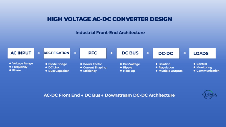
Understand how an AC-DC front end establishes the DC bus used by downstream DC-DC converters and low-voltage power domains.