We help the world since 2012

High Voltage AC-DC Converter Design Considerations for Industrial Power Systems
When an industrial system is powered directly from an AC source, the first power-conversion stage often determines how the rest of the equipment receives and manages electrical power.
A high-voltage AC-DC converter can transform an AC input into a regulated DC bus or a defined DC output for downstream electronics, control systems, industrial automation equipment, monitoring circuits, and other power-conversion stages.
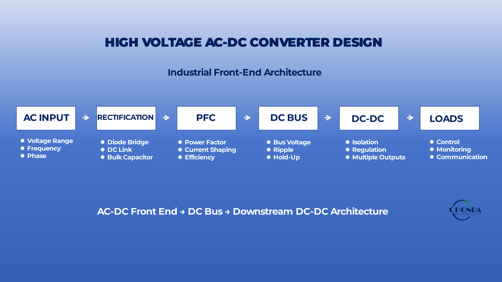
A simplified industrial power architecture may look like:
AC Input → AC-DC Converter → DC Bus → DC-DC Converter → Control / Load
The AC-DC stage therefore often serves as the front-end power-conversion stage of the complete system.
However, selecting or designing a high-voltage AC-DC converter involves more than converting AC into DC.
Engineers may also need to consider:
- Input-voltage range
- Rectification
- Power factor
- Isolation
- Output regulation
- Hold-up requirements
- Efficiency
- EMI
- Thermal performance
- Protection
- Inrush current
- Mechanical integration
These requirements interact with each other.
For example, adding power-factor correction can improve input-current behavior but also introduce another active power stage. Increasing switching frequency may reduce magnetic size while creating additional switching losses and EMI challenges. Increasing isolation may affect both the transformer structure and the thermal path.
For industrial equipment, the AC-DC converter should therefore be treated as part of the overall power architecture rather than as an isolated component.
This guide examines the main design considerations engineers should evaluate when developing or selecting a high-voltage AC-DC converter for industrial power systems, with particular attention to how the front-end converter interacts with the downstream DC bus and DC-DC conversion stages.
1. What Role Does the AC-DC Front End Play?
In many industrial power systems, the AC-DC converter is the first major power-conversion stage between the incoming electrical supply and the DC power architecture used by the equipment.
Rather than viewing the AC-DC converter as an isolated power supply, it is more useful to treat it as the front-end stage that establishes the electrical conditions for everything downstream.
A simplified industrial architecture may look like:
AC Input → AC-DC Front End → DC Bus → DC-DC Conversion → Control / Monitoring / Load
The AC-DC stage therefore has responsibilities that extend beyond simply producing a DC output.
1.1 Establishing the DC Bus
One of the most important roles of the AC-DC front end is to establish a usable DC bus for downstream power stages.
The DC bus may feed:
- DC-DC converters
- Motor or actuator control systems
- Industrial controllers
- Monitoring electronics
- Communication circuits
- Other auxiliary power stages
The voltage level and stability of this bus influence the design choices made throughout the rest of the equipment.
For example, if the downstream DC-DC stage is designed to operate from a defined high-voltage DC range, the AC-DC front end must provide a bus that remains within the required limits under normal operating and transient conditions.
1.2 Acting as the Interface Between the Utility Supply and the Equipment
The AC source and the internal DC architecture of an industrial system have very different electrical characteristics.
The front-end converter forms the interface between them.
It must therefore accommodate the expected AC input conditions while delivering the electrical characteristics required by the internal system.
This can include considerations such as:
- Input-voltage variation
- Frequency variation
- Startup behavior
- Input current
- DC-bus voltage
- Output regulation
- Protection
The front end is consequently one of the first places where the external electrical environment meets the equipment’s internal power architecture.
1.3 Supporting Downstream DC-DC Conversion
In more complex industrial equipment, the AC-DC stage may not generate the final voltage required by every load.
Instead, it may establish an intermediate DC bus that is then converted by one or more downstream DC-DC modules.
For example:
AC Input → AC-DC Front End → High-Voltage DC Bus → Isolated DC-DC → 24V Control
or:
AC Input → AC-DC Front End → DC Bus → Multiple DC-DC Modules → Different Loads
In this architecture, the AC-DC stage and downstream DC-DC stages should be designed as parts of one power system.
The front-end bus voltage, allowable ripple, transient behavior, and available power can directly affect the performance of the downstream converters.
1.4 Defining the Starting Point for Power Quality
The front end also influences the electrical quality of the internal DC bus.
Depending on the architecture, the AC-DC stage may need to manage:
- Input current waveform
- DC-bus ripple
- Voltage stability
- Transient response
- Common-mode behavior
- Power factor
These characteristics can influence the performance of sensitive downstream circuits.
For example, a monitoring or control system may tolerate the required DC voltage but still be affected by excessive ripple or disturbances originating from the front-end stage.
1.5 The Front End Often Determines the Overall Power Architecture
Once the AC-DC stage and DC bus are defined, many downstream design decisions become easier to establish.
The engineering team can then determine:
- Which loads can use the DC bus directly
- Which loads require DC-DC conversion
- Where galvanic isolation is needed
- How power should be distributed
- Where protection should be applied
- How thermal loads are distributed
This means that the AC-DC front end often acts as the starting point for the complete power architecture.
A poorly defined front-end requirement can create problems further downstream, even when the individual DC-DC converters are correctly designed.
1.6 Front-End and Downstream Stages Should Be Sized Together
The AC-DC converter should also be evaluated against the expected downstream load profile.
If several DC-DC converters are connected to the same DC bus, the front-end power requirement should reflect their realistic combined operating conditions rather than simply adding every theoretical maximum value without considering actual simultaneity.
At the same time, the front end must be capable of handling realistic peak or transient conditions.
This creates a system-level relationship:
AC Input → AC-DC Power Capability → DC Bus → Downstream Conversion → Final Loads
The weakest stage in this chain can become the effective limit of the complete power architecture.
1.7 Why the Front End Matters in Industrial Equipment
Industrial systems often operate continuously, under variable environmental conditions, and with multiple electronic subsystems running at the same time.
The AC-DC front end therefore needs to provide a stable foundation for the rest of the power system rather than simply meet a nominal voltage specification.
Its design can influence:
- Downstream converter selection
- Thermal behavior
- EMI performance
- Protection strategy
- DC-bus stability
- System reliability
For this reason, the AC-DC front end should be treated as a system-level power interface rather than an isolated conversion component.
The next step is to define the actual AC input conditions, including voltage range, frequency, phase configuration, and expected operating extremes, before selecting the rectification and front-end architecture.
2. Define the AC Input Requirements
Before selecting or designing a high-voltage AC-DC converter, engineers should first define the actual AC input conditions of the equipment.
The input specification is more than a nominal voltage value.
The converter may need to operate across a defined voltage range, at a specific line frequency, with either a single-phase or three-phase supply, while also tolerating normal variations and expected disturbances from the upstream electrical system.
A clear definition of these conditions provides the foundation for the rest of the front-end design.
2.1 Input Voltage
The first parameter is the nominal AC input voltage.
Depending on the application, the equipment may be designed for a specific industrial or utility supply, or it may need to support several nominal voltages.
For example, an industrial system may be designed for a defined mains voltage, while an international product may need to support more than one AC supply standard.
The nominal value alone, however, is not enough.
The converter should be designed around the actual voltage range that can occur during operation.
2.2 Input-Voltage Range
The minimum and maximum expected AC input voltages should be defined before selecting the front-end stage.
For example, a specification may require the converter to operate across a stated AC input range rather than at one fixed voltage.
This matters because the AC input affects:
- Rectifier output
- DC-bus voltage
- Input current
- Component voltage stress
- PFC operating conditions
- Protection thresholds
- Downstream converter requirements
The minimum input condition and maximum input condition can therefore create different design challenges.
At low input voltage, the converter may need to process higher input current for the same output power.
At high input voltage, the voltage stress on the rectification and switching stages can increase.
Both extremes should be considered during the initial architecture definition.
2.3 Input Frequency
The required AC line frequency should also be defined.
For many industrial applications, the front-end converter may need to operate across a specified frequency range rather than a single fixed frequency.
Input frequency can influence the behavior of:
- Input filtering
- Rectification
- Magnetic components
- Control circuits
- Power-factor correction
Although modern power electronics can support a wide range of AC frequencies, the actual converter design should still be verified against the intended operating environment.
2.4 Single-Phase or Three-Phase Input
The number of AC phases is another fundamental architectural decision.
A lower-power industrial system may use a single-phase input, while higher-power industrial equipment may use a three-phase supply.
The choice affects the front-end topology, input-current distribution, rectification structure, power level, and DC-bus behavior.
For example:
Single-Phase AC → Rectifier / PFC → DC Bus
may be appropriate for a lower-power system.
A higher-power industrial architecture may instead use:
Three-Phase AC → Three-Phase Rectifier / Active Front End → DC Bus
The appropriate configuration depends on the available facility power and the required output power of the equipment.
2.5 Normal Input Variation
Industrial AC supplies do not necessarily remain exactly at their nominal voltage.
The converter should therefore be evaluated against the expected normal operating variation of the source.
This is particularly important for equipment installed in environments where:
- Multiple loads share the same supply
- Long cable runs are present
- Large motors or drives are connected nearby
- The upstream electrical system has significant voltage variation
The AC-DC front end should remain within its specified operating range under these expected conditions.
2.6 Startup and Input Transients
The input specification should also consider what happens when the equipment is switched on or when the upstream supply changes suddenly.
The front end may experience:
- Input-voltage transients
- Inrush current
- Short-duration disturbances
- Repeated startup events
- Temporary voltage dips
These conditions can influence the design of input protection, rectification, bulk capacitance, and control behavior.
They should therefore be considered during the initial input-requirement definition rather than added only after the main converter has been selected.
2.7 The AC Input Defines the Front-End Design Space
Once the engineer has defined:
Input Voltage + Input Range + Frequency + Phase Configuration
the available front-end architectures become much easier to evaluate.
For example, a relatively low-power single-phase system may use a conventional rectifier followed by PFC and a regulated DC bus.
A higher-power three-phase system may require a different rectification and power-conversion architecture.
The input specification therefore acts as the first filter for the possible AC-DC solutions.
2.8 Define the Real Input Envelope
A useful way to document the requirement is to define the complete input envelope before selecting the converter:
Nominal Voltage → Minimum Voltage → Maximum Voltage → Frequency Range → Phase Configuration → Expected Transients
This provides a practical reference for evaluating the rectifier, PFC stage, switching devices, protection components, and downstream DC-bus requirements.
A high-voltage AC-DC converter should ultimately be selected for the real input conditions of the equipment, not simply for the nominal voltage printed on the equipment specification.
Once the input envelope is defined, the next design question is how the AC waveform should be rectified and converted into the DC bus required by the rest of the power system.
3. Rectification and DC-Bus Formation
After the AC input requirements have been defined, the next step is to determine how the incoming AC waveform will be converted into the DC bus used by the rest of the power system.
In a typical industrial AC-DC front end, the process can be viewed as:
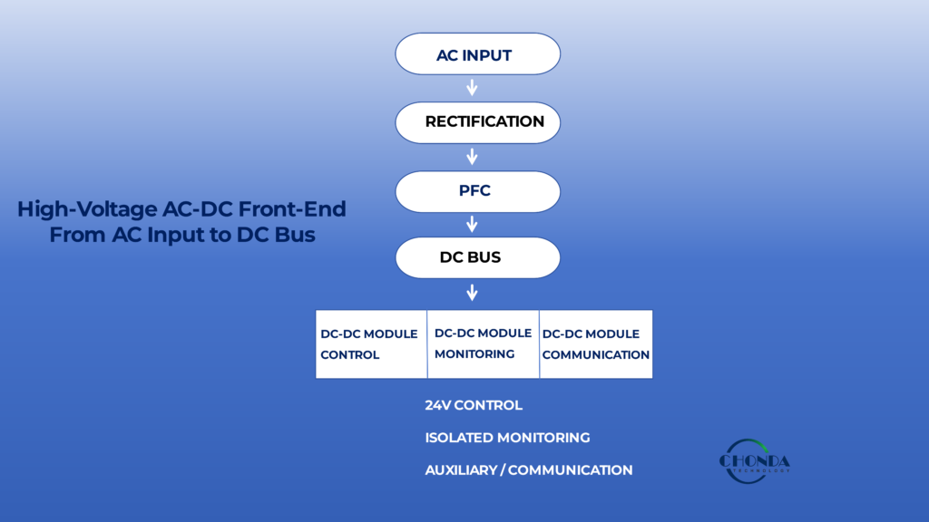
AC Input → Rectification → DC-Link / DC Bus → Downstream Power Conversion
The rectifier converts the alternating input into a unidirectional voltage, while the DC-link section stores and smooths energy so that downstream circuits receive a more usable DC supply.
The resulting DC bus becomes the electrical foundation for the rest of the power architecture.
3.1 From AC Waveform to Rectified Voltage
The first conversion stage is rectification.
A rectifier changes the polarity of the incoming AC waveform so that the downstream circuit sees a unidirectional voltage.
For a basic industrial front end, this may be implemented with a diode bridge or another rectifier topology depending on the input phase configuration and power level.
A simplified single-phase architecture is:
AC Input → Rectifier → DC-Link Capacitor → DC Bus
For a three-phase system, the rectification structure is different, but the underlying purpose is the same:
Convert the incoming AC source into a usable DC energy path for the downstream power stages.
3.2 The DC-Link Provides Energy Storage
After rectification, the voltage is not necessarily a perfectly constant DC level.
The DC-link section usually includes energy-storage and filtering elements that reduce the variation of the rectified waveform and provide a more stable electrical source for the following stages.
Depending on the architecture, the DC-link may include:
- Bulk capacitors
- Filtering components
- Precharge circuits
- Voltage sensing
- Protection components
The DC-link therefore performs more than simple filtering.
It also provides short-term energy storage between the AC input and the downstream power stages.
3.3 Why the DC Bus Matters to the Rest of the System
Once the DC bus has been established, downstream converters no longer have to process the original AC waveform.
They can instead operate from a defined DC input environment.
For example:
AC Input → AC-DC Front End → 400VDC Bus → Isolated DC-DC → 24V Control
or:
AC Input → AC-DC Front End → DC Bus → Multiple DC-DC Modules → Different Loads
This separation can simplify the rest of the power architecture because the downstream converters are designed around a known DC operating range.
3.4 The DC Bus Is Not Automatically Fixed
The actual DC-bus voltage depends on the front-end architecture and operating conditions.
It can be influenced by:
- AC input voltage
- Rectifier topology
- PFC stage
- Control strategy
- Load level
- DC-link capacitance
- Input transients
For this reason, engineers should define the expected DC-bus operating range before selecting downstream DC-DC converters.
A downstream converter that operates correctly at one nominal bus voltage may not be suitable if the real bus voltage varies significantly during startup, normal operation, or transient conditions.
3.5 Passive and Active Front Ends
A simple rectifier and DC-link capacitor can provide a straightforward AC-to-DC conversion path.
For some systems, however, additional active control is required to improve input-current behavior, regulate the DC bus, or meet power-quality requirements.
This can lead to an architecture such as:
AC Input → Rectification / PFC → Regulated DC Bus → DC-DC Conversion
The exact front-end structure depends on the application power level, power-quality requirements, efficiency target, and system architecture.
The important point is that the DC bus remains the bridge between the AC source and the downstream DC power system.
3.6 DC-Bus Voltage and Downstream Converter Selection
The DC bus establishes one of the most important electrical inputs for any downstream DC-DC converter.
For example, if the front end creates a bus with a defined operating range, the DC-DC stage should be selected or designed to tolerate that range under the required output load.
This creates a direct relationship:
AC Input Range → Rectifier / PFC → DC-Bus Range → DC-DC Input Range
If the front-end bus is poorly defined, downstream converter selection becomes more difficult.
If the DC-bus range is clearly specified, the downstream design can be evaluated more systematically.
3.7 DC-Bus Ripple Matters
The DC bus is not only defined by its average voltage.
Ripple and transient behavior can also affect the downstream system.
Excessive ripple may increase stress on downstream capacitors or converters, while sudden bus disturbances may affect control circuits or cause protection functions to activate.
The front-end design should therefore consider:
Bus Voltage + Ripple + Transient Behavior
rather than using the nominal DC-bus voltage as the only specification.
3.8 Precharge and Startup Behavior
A high-voltage DC-link can contain significant stored energy.
When the equipment is first connected to the AC source, the bulk capacitors may initially appear as a low-impedance load.
Without an appropriate precharge strategy, the resulting inrush current can become very large.
Industrial AC-DC front ends may therefore use precharge circuits or controlled startup methods to limit the initial current and protect upstream components.
This is one of the reasons that DC-bus formation cannot be considered purely as a voltage-conversion problem.
The way the bus is charged can also influence the reliability of the complete equipment.
3.9 The DC Bus as the Architectural Boundary
A useful way to think about the system is:
AC Side
→ Input Voltage
→ Frequency
→ Rectification
→ PFC / Front-End Control
DC Side
→ DC Bus
→ DC-DC Conversion
→ Regulation
→ Isolation
→ Loads
The DC bus forms the boundary between these two parts of the power architecture.
This makes it an important reference point for power budgeting, protection coordination, thermal analysis, and downstream converter selection.
3.10 The Front End Establishes the Starting Conditions for Downstream Power Conversion
The main design principle is:
A downstream DC-DC converter can only be designed correctly when the DC bus feeding it is properly defined.
The front-end engineer therefore needs to specify not only the nominal bus voltage, but also its expected range, ripple, transient behavior, startup conditions, and available power.
Once these conditions are established, the next question is how the AC-DC front end should control the input current and power factor.
That leads directly to the role of power-factor correction (PFC) in industrial AC-DC converter design.
4. Power Factor and PFC
Once the rectifier and DC bus have been defined, engineers also need to consider how the AC-DC front end draws power from the AC source.
For many industrial systems, simply converting AC into DC is not enough. The shape of the input current can also affect how efficiently the equipment uses the available AC supply and how much electrical disturbance it creates on the upstream network.
This is where power factor correction (PFC) becomes relevant.
The purpose of PFC is to improve the relationship between the AC voltage waveform and the current drawn by the converter so that the front end uses the available input power more effectively.
4.1 Why Power Factor Matters in an Industrial Front End
A conventional rectifier followed by a large DC-link capacitor can draw current in short pulses around the peaks of the AC waveform.
Although the converter may still provide the required DC power, this non-sinusoidal input current can increase harmonic content and make the AC source appear more heavily loaded than a more controlled current waveform would require.
For industrial equipment, this can affect:
- Input current
- Harmonic distortion
- Upstream equipment loading
- Power distribution
- System-level power quality
The importance of these effects depends on the power level, installation environment, and applicable requirements.
4.2 What PFC Changes
A PFC stage is placed in the front end so that the input current can be controlled more closely relative to the AC voltage waveform.
A simplified architecture may therefore become:
AC Input → Rectifier → PFC → DC Bus
instead of:
AC Input → Rectifier → DC Bus
The PFC stage can therefore become an important part of the front-end architecture rather than simply an optional add-on.
4.3 PFC Can Also Help Establish a More Predictable DC Bus
In many AC-DC architectures, the PFC stage does more than improve input-current behavior.
It can also provide a more controlled DC-bus condition for downstream conversion.
This can be useful when one or more DC-DC converters are connected to the bus and need a defined input-voltage range.
The complete architecture may therefore look like:
AC Input → Rectification → PFC → Regulated DC Bus → DC-DC Modules
In this arrangement, the PFC stage becomes part of the interface between the AC source and the downstream DC power architecture.
4.4 PFC Is Not Free
Adding PFC introduces another active power-conversion stage.
This can increase:
- Component count
- Control complexity
- Switching losses
- Thermal load
- Cost
- EMI design requirements
The decision to use PFC should therefore be based on the actual system requirements.
For a low-power application with relatively simple input requirements, adding a more complex front-end architecture may provide limited practical benefit.
For higher-power industrial equipment, however, improved input-current behavior and better control of the DC bus may justify the additional circuitry.
4.5 Passive and Active PFC
PFC can be implemented in different ways.
A simpler approach may use passive components to influence the input-current behavior.
An active PFC stage uses controlled switching devices and feedback to shape the input current more precisely.
The appropriate approach depends on:
- Input power
- Required power factor
- Harmonic requirements
- Efficiency target
- Cost
- System complexity
The objective is not to choose the most sophisticated PFC topology available.
It is to meet the actual input and system requirements with an appropriate level of complexity.
4.6 PFC and Downstream DC-DC Conversion
The presence of PFC also affects how the rest of the power architecture is designed.
For example:
AC Input → PFC → High-Voltage DC Bus → Isolated DC-DC → 24V Load
In this architecture, the DC-DC converter does not need to deal directly with the original AC waveform.
Instead, it operates from the DC bus established by the front-end stage.
This separation can make the overall architecture easier to analyze, but it also means that the PFC and downstream converter need to be compatible in terms of:
- Bus voltage
- Power capability
- Transient behavior
- Control interaction
- Protection
4.7 PFC Should Be Considered at the System Level
The PFC stage should therefore not be evaluated only by its power-factor number.
Engineers should consider how it affects the complete front end:
AC Input → Input Current → PFC → DC Bus → Downstream Conversion
A PFC stage may improve input-current quality while adding another source of switching loss and heat.
The design must therefore balance:
Power Quality + Efficiency + Thermal Performance + EMI + Cost
4.8 When PFC Becomes an Important Design Requirement
PFC becomes more relevant as the power level and system requirements increase.
It may be particularly important when:
- The equipment draws substantial power from the AC supply.
- Input harmonic performance is important.
- The equipment must meet defined power-quality requirements.
- The downstream DC architecture benefits from a more controlled bus.
- The equipment operates continuously at significant load.
The exact requirement should come from the application and the relevant electrical environment rather than from the assumption that every AC-DC converter must use the same front-end topology.
4.9 The Practical Design Principle
For an industrial AC-DC converter, PFC should be viewed as part of the overall front-end architecture.
The main question is not:
“Should we add PFC?”
It is:
“What input-current behavior and DC-bus conditions does the system require, and what front-end architecture provides them with acceptable efficiency, thermal performance, EMI, and complexity?”
Once the PFC and DC-bus requirements are established, the next design consideration is the isolation strategy and the safety requirements between the AC input, the DC bus, and downstream power domains.
5. Isolation and Safety Requirements
Isolation is one of the most important considerations when an AC-DC converter is integrated into an industrial power system.
The front end may be directly connected to the incoming AC supply, while the downstream DC bus may feed control electronics, communication circuits, monitoring systems, or other accessible power domains.
The electrical relationship between these domains must therefore be defined before the converter structure is finalized.
Isolation is not simply a specification such as “1500VAC” or “3000VAC.”
The complete insulation system also depends on the working voltage, transient conditions, physical spacing, insulation materials, pollution environment, and the way the converter is installed in the final equipment.
5.1 Why Isolation May Be Required
The AC input can represent a significantly different electrical environment from the downstream electronics.
Galvanic isolation may be required to:
- Separate hazardous voltage from accessible circuits
- Prevent unwanted DC conduction paths
- Establish a defined electrical boundary
- Protect downstream control or monitoring electronics
- Support system grounding requirements
In some industrial systems, isolation is required across the main AC-DC conversion stage.
In others, the front-end DC bus may remain within one power domain while isolation is introduced later by a downstream DC-DC stage.
This means the isolation strategy should be considered at the system level, not automatically assigned to one particular converter stage.
5.2 Isolation Voltage Is Not the Same as Working Voltage
A common mistake is to treat the dielectric withstand rating as if it completely defines the isolation capability of the converter.
For example, a converter may have a specified isolation test voltage, but that value describes a particular test condition.
The continuous electrical environment is determined by the actual working voltage and expected transients.
Engineers should therefore distinguish between:
Working Voltage
and:
Dielectric Withstand / Hi-Pot Test Voltage
The two specifications serve different purposes and should not be interpreted as interchangeable.
5.3 Creepage and Clearance
Physical spacing is another fundamental part of the isolation system.
Clearance refers to the shortest distance through air between conductive parts.
Creepage refers to the shortest distance along the surface of an insulating material.
Both can become critical in high-voltage AC-DC converters.
For example, a PCB may have enough direct air distance between two conductors while still providing insufficient surface distance along the board.
The required spacing depends on factors such as:
- Working voltage
- Pollution environment
- Insulation type
- Material characteristics
- Applicable safety requirements
The final spacing should therefore be determined from the actual application and applicable standards rather than from a generic rule.
5.4 Insulation Is Part of the Complete Architecture
Isolation is created by more than the transformer or one insulating layer.
The complete insulation system may include:
- Transformer insulation
- PCB substrate
- Insulating barriers
- Spacers
- Potting or encapsulation
- Connector insulation
- Mechanical structures
A strong isolation design must remain effective across the complete power path and under the expected operating environment.
A component with a high isolation rating cannot compensate for insufficient creepage or clearance elsewhere in the assembly.
5.5 High-Voltage AC-DC Systems Must Consider Transients
Industrial AC inputs can experience transient events that are significantly higher than the nominal operating voltage.
The insulation system should therefore be evaluated not only against the normal AC input but also against the expected transient environment.
This can influence:
- Creepage
- Clearance
- Insulation thickness
- Component selection
- Surge protection
- Transformer design
The isolation system should be designed around the complete electrical environment rather than a single nominal voltage value.
5.6 Isolation and PFC / DC-Bus Architecture
The isolation strategy also affects where the isolation boundary is placed.
For example, an industrial system could use:
AC Input → PFC → Isolated DC Bus → Downstream DC-DC
or:
AC Input → Non-Isolated Front End → DC Bus → Isolated DC-DC
Both approaches can be technically valid, but they create different requirements for the front end, downstream conversion stage, grounding, protection, and mechanical structure.
The appropriate isolation boundary depends on the complete equipment architecture.
5.7 Safety Requirements Influence Mechanical Design
High-voltage isolation requirements can affect the physical construction of the entire converter.
For example, engineers may need to reserve space for:
- Isolation barriers
- Creepage paths
- Clearance zones
- Connector separation
- Protective structures
- Insulating materials
This means that a mechanically compact converter cannot be designed only from an electrical schematic.
The physical arrangement of conductive and insulating structures is part of the safety design.
5.8 Isolation and Thermal Design Can Conflict
In many industrial converters, the same physical interface may need to provide both electrical isolation and thermal conduction.
An insulating barrier may be necessary to meet the required isolation but can add thermal resistance.
This creates a design trade-off:
Electrical Insulation ↔ Thermal Path
The solution must satisfy both requirements.
This is particularly important when a high-loss component must be thermally connected to a chassis, heat spreader, or other cooling structure while remaining electrically isolated from it.
5.9 Verify the Complete Isolation Path
Before finalizing the AC-DC converter, engineers should verify the complete isolation boundary rather than checking only the transformer or primary component.
A practical review should follow:
AC Input → Isolation Barrier → DC Bus → Downstream Power Domains
and consider the actual physical implementation of every crossing point.
The relevant questions include:
Where is the isolation boundary?
What is the continuous working voltage?
What transient conditions must be tolerated?
Are creepage and clearance adequate?
Does the insulation system remain effective under the intended environmental conditions?
5.10 Safety Should Be Designed Into the Front End
Isolation should therefore not be treated as a final compliance check added after the converter has already been designed.
The required working voltage, insulation structure, creepage, clearance, and protection strategy can influence the architecture from the beginning.
For deeper discussion of isolation architecture and high-voltage insulation considerations, see High Voltage DC-DC Converter Isolation Design: Principles and Applications.
The practical principle is:
A safe AC-DC front end is not defined by one isolation-voltage number. It is defined by the complete insulation system under the actual working and transient conditions of the equipment.
6. Output Regulation and DC-Bus Requirements
Once the AC input, rectification, PFC, and isolation requirements have been defined, the next question is how the AC-DC front end should establish the DC bus for the downstream power stages.
The DC bus is not simply a voltage number.
For a downstream DC-DC converter, the bus also defines the available input-voltage range, ripple, transient behavior, power capability, and startup conditions that the converter must handle.
A well-designed AC-DC front end should therefore provide a DC bus that gives the downstream stages a predictable and usable operating environment.
6.1 The DC Bus Should Be Defined as a Range
Engineers should avoid specifying the bus only as a nominal value such as:
400VDC
The downstream converter needs to know the actual operating range.
For example:
DC Bus: 360–420VDC
provides much more useful information than simply stating:
DC Bus: 400VDC
The range may be influenced by:
- AC input variation
- PFC control
- Load changes
- Startup
- Transient conditions
- Protection limits
The downstream DC-DC converter should then be selected or designed to operate reliably across this complete range.
6.2 Regulation Determines What the Downstream Converter Sees
A tightly regulated DC bus can provide a more predictable input to downstream conversion stages.
For example:
AC Input → AC-DC / PFC → Regulated 400VDC Bus → Isolated DC-DC → 24V
allows the DC-DC stage to be designed around a relatively well-defined input condition.
In another architecture, the AC-DC stage may provide a wider or less tightly regulated bus, requiring the downstream converter to tolerate a broader input range.
Neither approach is automatically better.
The appropriate choice depends on the required system architecture and the capabilities of the downstream converter.
6.3 The AC-DC and DC-DC Stages Should Be Designed Together
The front-end bus and the downstream DC-DC input range should not be specified independently.
For example, if the AC-DC stage can produce:
300–450VDC
but the downstream converter is only designed for:
360–420VDC
the two stages are not actually compatible across the complete operating range.
A practical design sequence is therefore:
AC Input Range → AC-DC DC-Bus Range → DC-DC Input Range → Final Output Requirement
This prevents the front end from creating operating conditions that the downstream converter cannot tolerate.
6.4 DC-Bus Ripple Matters to the DC-DC Stage
The downstream converter does not see only the average bus voltage.
It also experiences the ripple and transient variation superimposed on that voltage.
Excessive bus ripple can increase:
- Input capacitor ripple current
- Semiconductor stress
- Control-loop activity
- Audible or electrical noise in some systems
- Thermal losses
The required ripple level therefore depends on the downstream converter topology, control scheme, power level, and application.
For sensitive monitoring or control systems, the quality of the DC bus can become particularly important.
6.5 Transient Response and Bus Stability
The AC-DC front end should also maintain an acceptable bus condition when the downstream load changes.
For example, if a DC-DC converter suddenly increases its input power demand, the AC-DC stage and DC-link must respond without creating excessive bus-voltage disturbance.
Likewise, if a downstream load is suddenly removed, the bus voltage should remain within the limits expected by the connected converters.
The interaction can therefore be viewed as:
Load Change → DC-DC Input Demand → DC-Bus Response → AC-DC Front-End Response
This is a system-level dynamic rather than an isolated AC-DC specification.
6.6 DC-Bus Power Capability
The front-end DC bus must also provide sufficient power for the complete downstream system.
If several DC-DC modules are connected to the bus, the AC-DC front end should be evaluated using the realistic combined load profile.
For example:
AC-DC Front End
↓
DC-DC Module A — Control
DC-DC Module B — Monitoring
DC-DC Module C — Communication
The front-end power requirement should reflect how these modules actually operate together, including continuous load, peak demand, startup, and other realistic conditions.
This avoids both undersizing the AC-DC stage and unnecessarily oversizing it based on theoretical maximums that can never occur simultaneously.
6.7 Hold-Up and Energy Storage Requirements
The DC bus may also need to maintain power during a short interruption or input disturbance.
The required hold-up time can influence the amount of energy-storage capacitance and therefore affect:
- DC-bus voltage
- Capacitor size
- Ripple current
- Startup behavior
- Mechanical volume
- Thermal design
The required hold-up behavior should therefore be defined before finalizing the DC-link architecture.
6.8 Bus Voltage Influences Downstream Converter Design
The DC-bus voltage also affects the design and selection of the downstream DC-DC converter.
A higher bus voltage may reduce the input current required for a given power level, but it can increase electrical stress on the downstream switching devices and insulation structures.
A wider bus range can provide greater system flexibility, but it may also require a wider-input DC-DC converter.
This creates a direct architectural relationship:
DC-Bus Voltage → DC-DC Input Stage → Semiconductor Stress → Magnetic Design → Thermal Performance
The AC-DC front end therefore has a direct influence on the design complexity of the downstream converter.
6.9 A Practical DC-Bus Specification
Before selecting the downstream DC-DC stage, the AC-DC front end should ideally define:
Nominal Bus Voltage
Minimum / Maximum Bus Voltage
Bus Ripple
Transient Limits
Available Continuous Power
Peak Power Capability
Startup Conditions
Hold-Up Requirement
These parameters provide the DC-DC designer with a realistic electrical envelope.
6.10 The DC Bus Is the Contract Between the Two Conversion Stages
A useful way to think about the architecture is that the DC bus forms a kind of electrical contract between the AC-DC front end and the downstream DC-DC stage.
The AC-DC front end is responsible for creating an acceptable bus.
The DC-DC converter is responsible for operating reliably within that specified bus envelope.
When these two stages are designed together, the complete power architecture becomes easier to evaluate and optimize.
The practical principle is:
The best AC-DC front end is not simply the one that produces the desired DC voltage. It is the one that provides a DC-bus environment that the downstream power architecture can reliably use.
7. Efficiency and Thermal Considerations
The efficiency of the AC-DC front end directly affects the amount of heat generated before power reaches the downstream DC bus.
This makes front-end efficiency more than an energy-consumption parameter. In an industrial power system, the losses generated by the AC-DC stage become part of the thermal load of the complete equipment.
A front end that supplies a stable DC bus but dissipates excessive power may create unnecessary thermal stress for the enclosure, cooling system, and downstream power architecture.
7.1 Where the AC-DC Front-End Losses Come From
Power loss in an AC-DC converter can occur across several stages of the front end.
Typical sources include:
- Rectifier conduction losses
- PFC switching losses
- PFC conduction losses
- Magnetic losses
- Capacitor and passive-component losses
- Gate-drive and control losses
- PCB and interconnection losses
The actual distribution depends on the front-end topology and operating conditions.
For a system using rectification followed by active PFC, the PFC stage may become a significant contributor to total front-end loss.
7.2 Efficiency Changes with Operating Conditions
AC-DC efficiency should not be treated as a single fixed number.
It can change with:
- AC input voltage
- Output power
- Load level
- Switching frequency
- Ambient temperature
- PFC operating conditions
For example, a front end may achieve high efficiency near its intended operating point while showing different performance under light load or near its maximum continuous power.
This matters when the equipment spends a significant amount of time away from its nominal operating condition.
7.3 Light Load Can Be Especially Relevant
Industrial equipment may not always operate at maximum power.
A control cabinet, monitoring system, or embedded industrial platform may spend much of its operating time at a relatively low load while occasionally reaching a higher power level.
In these conditions, the front-end’s fixed losses and control consumption can become more noticeable relative to the useful output power.
The engineer should therefore consider not only:
What is the maximum efficiency?
but also:
What is the efficiency at the operating conditions the equipment will use most often?
7.4 Front-End Losses Become Heat
The power not delivered to the DC bus becomes heat inside the AC-DC stage.
For example, if an AC-DC front end delivers 500W at 94% efficiency, approximately 30W is lost inside the conversion stage.
That 30W may be distributed across the rectifier, switching devices, magnetic components, capacitors, PCB structures, and other parts of the front end.
The complete equipment must then remove this heat through its cooling environment.
The thermal consequence is therefore directly related to the front-end efficiency.
7.5 Front-End Heat Affects the DC Bus and Downstream Stages
The thermal impact of the AC-DC stage does not stop at the front end.
If the front-end temperature rises significantly, the surrounding environment may become hotter for downstream components connected to the same enclosure.
This can reduce the available thermal margin of:
- DC-DC converters
- Control electronics
- Capacitors
- Communication circuits
- Other heat-sensitive components
The front end should therefore be evaluated as one of the heat-generating elements within the complete enclosure.
7.6 Efficiency and Power Density Must Be Considered Together
A high-efficiency AC-DC converter usually produces less heat for the same output power.
This can provide more freedom to create a compact front-end structure.
However, increasing power density can also make heat removal more difficult if the remaining losses are concentrated within a smaller volume.
The practical objective is therefore:
Efficient Conversion + Manageable Thermal Density
rather than maximum efficiency or minimum physical size considered separately.
7.7 Input Voltage Can Affect Efficiency and Thermal Load
The same AC-DC converter may show different efficiency at different input voltages.
This can be influenced by changes in:
- Input current
- Rectifier losses
- PFC operating point
- Switching conditions
- Magnetic behavior
For an international or wide-input industrial product, the efficiency should therefore be reviewed across the expected AC input range rather than only at one nominal voltage.
7.8 Thermal Design Should Follow the Actual Front-End Loss Distribution
The location of the heat-generating components matters as much as the total loss.
A small rectifier, PFC switch, magnetic component, or other device may become locally hot if its heat-transfer path is limited.
The AC-DC front end should therefore be evaluated with respect to:
Loss Source → Heat Spreading → Cooling Structure → Ambient
The objective here is not to repeat a full thermal-bottleneck analysis, but to ensure that the front-end losses are compatible with the available thermal environment.
7.9 Efficiency Has a System-Level Effect
The AC-DC front end establishes the first major power-conversion stage of the equipment.
If its efficiency is poor, more power must be drawn from the AC source and more heat must be removed from the equipment.
That can influence:
- Input current
- Cooling requirements
- Enclosure temperature
- Downstream thermal margin
- Overall system efficiency
In a multi-stage architecture, these effects accumulate.
For example:
AC Input → AC-DC → DC Bus → DC-DC → Load
If both the AC-DC and DC-DC stages introduce significant losses, the complete system efficiency may be substantially lower than the efficiency of either stage considered individually.
7.10 The Practical Front-End Objective
The AC-DC front end should therefore provide the required DC-bus power while keeping its own losses within a level that the final equipment can thermally and mechanically accommodate.
The practical objective is not simply:
Achieve the highest efficiency number.
It is:
Deliver the required DC-bus power with acceptable loss, thermal load, efficiency across the expected operating range, and long-term reliability.
Once the efficiency and thermal behavior of the front end are understood, the next design consideration is how switching activity and input-current behavior can affect EMI and electrical compatibility with the surrounding industrial system.
8. EMI and Input-Side Noise
An AC-DC converter does not interact only with the DC loads connected to its output.
It also interacts with the AC source that feeds the equipment.
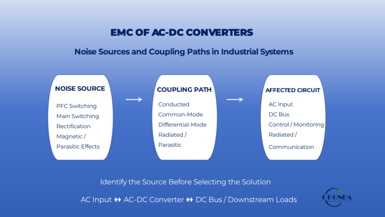
Rectification, PFC switching, high-frequency transitions, and input-current shaping can introduce electrical noise and harmonic currents into the AC input path. In an industrial environment, these disturbances may propagate through the power distribution network and interact with other equipment connected to the same supply.
For this reason, the input side of an AC-DC converter deserves separate attention from the downstream DC-DC stages.
8.1 The AC Input Is Also a Noise Path
A high-voltage AC-DC front end contains switching devices, rectifiers, inductors, capacitors, and other components that operate with rapidly changing voltages and currents.
Some of the resulting high-frequency energy can couple back toward the AC input.
A simplified power path is:
AC Source → Input Network → Rectifier / PFC → DC Bus
But the high-frequency noise path may extend in the opposite direction:
Switching Activity → Parasitic / Filtering Paths → AC Input → Upstream Network
This means that an AC-DC converter can become a source of conducted disturbance even when its DC output is operating correctly.
8.2 Rectifier and PFC Behavior Affect the Input Current
The shape of the current drawn from the AC source depends strongly on the front-end architecture.
A simple rectifier with a bulk capacitor can draw current in relatively narrow pulses around the peaks of the AC waveform.
Active PFC can shape the input current more closely to the AC voltage waveform, improving the input-current behavior.
However, the PFC switching stage introduces its own high-frequency switching activity.
The engineer therefore needs to consider both:
Low-Frequency Input Current Quality
and:
High-Frequency Conducted Noise
These are related, but they are not the same design problem.
8.3 Differential-Mode Noise on the AC Input
Differential-mode noise appears between the AC line conductors.
It can be generated by the changing input current of the converter and by switching activity within the front-end stage.
This noise can propagate toward the upstream supply if the input impedance and filtering network allow it.
In an industrial installation, several converters may share the same electrical distribution network.
A disturbance from one front end can therefore appear as part of the electrical environment seen by other equipment.
8.4 Common-Mode Noise and Leakage Paths
Common-mode noise can involve the relationship between the power-conversion stage, protective earth, chassis structures, and parasitic capacitances.
For an isolated AC-DC converter, high-frequency switching voltages can drive current through parasitic capacitances associated with:
- Transformer structures
- Heatsinks
- Chassis
- PCB structures
- Insulating materials
These currents can return through protective earth or other unintended paths.
The result can be electrical noise that is not obvious from the normal power path.
8.5 Input Filtering Is Part of the Front-End Architecture
Because the AC input is connected directly to the external power network, filtering at the front end can play an important role in controlling conducted noise.
The filter may need to address:
- Differential-mode noise
- Common-mode noise
- Switching harmonics
- High-frequency current paths
The filter should not be treated as an isolated add-on.
Its impedance interacts with the converter and can influence stability, losses, leakage current, and startup behavior.
The filter therefore needs to be considered together with the actual AC-DC power stage.
8.6 Input Filter and Converter Interaction
A front-end filter can improve conducted EMI, but adding significant impedance to the input path can also change the electrical behavior of the converter.
For example, the filter can affect:
- Input-voltage ripple
- Current response
- Control-loop behavior
- Startup
- Transient response
This is why simply adding a larger EMI filter does not necessarily guarantee a better overall design.
The filter and converter form one electrical system.
8.7 Industrial Environments Make Input-Side EMI More Important
Industrial equipment may share power distribution networks with:
- Motor drives
- Variable-frequency drives
- Contactors
- Other switching power supplies
- Measurement equipment
- Communication systems
The AC-DC front end therefore operates within a larger electromagnetic environment.
A converter that performs well in a laboratory may require additional attention when installed in a real industrial network with multiple switching loads and long power cables.
8.8 EMI, PFC, and Efficiency Are Connected
Input-side EMI design should also be considered together with PFC and efficiency.
For example, faster switching transitions may improve switching performance and reduce certain losses, but they can also increase high-frequency noise.
Similarly, additional filtering may reduce conducted noise while introducing its own losses and increasing physical size.
The front-end design therefore needs to balance:
Input Power Quality + EMI + Efficiency + Thermal Performance + Cost
Rather than optimizing one parameter independently.
8.9 Verify EMI Under Representative Operating Conditions
Input-side EMI should be evaluated under the conditions that the equipment will actually experience.
Useful conditions may include:
Minimum AC Input
Nominal AC Input
Maximum AC Input
Low Load
Typical Load
High Load
Different operating points can change the PFC behavior, switching activity, and input-current characteristics.
A converter should therefore be evaluated across its relevant operating envelope rather than at a single convenient test point.
8.10 AC-DC Input EMI Is Part of System Compatibility
The objective of input-side EMI design is not simply to make the AC-DC converter pass a laboratory measurement.
The front end should also coexist reliably with the surrounding electrical system.
This means considering:
AC Source → Input Filter → Rectifier / PFC → DC Bus → Downstream Power Architecture
as one connected electrical environment.
For detailed switching-noise, grounding, filtering, and PCB-level EMI mitigation techniques, see High Voltage DC-DC Converter EMI Design Considerations.
The practical principle is:
An AC-DC converter must control not only the power it delivers to the DC bus, but also the electrical noise it sends back into the AC system.
9. Protection and Inrush Current
Protection is an important part of a high-voltage AC-DC front end because the converter is directly connected to the incoming AC supply and often contains significant energy storage on the DC bus.
A properly designed front end must not only operate correctly under normal conditions. It should also respond predictably when the input voltage changes, when the DC-link is first energized, or when a downstream fault occurs.
One of the most important events to consider is inrush current.
9.1 Why Inrush Current Occurs
When an AC-DC converter is first connected to the AC source, the DC-link capacitors may initially have little or no charge.
From the perspective of the input source, these capacitors can briefly behave like a very low-impedance load.
This can create a large current pulse as the DC bus voltage rises.
A simplified startup sequence is:
AC Source → Rectifier → DC-Link Capacitor → Charging Current
The magnitude and duration of this current depend on the input conditions, capacitance, source impedance, and the charging method used by the front end.
9.2 Why a Large Inrush Current Is a System Problem
An excessive startup current can create several problems.
It may:
- Stress rectifier components
- Trigger upstream circuit protection
- Stress connectors and wiring
- Cause input-voltage disturbances
- Reduce component lifetime
- Produce unwanted electromagnetic disturbances
- Create repeated startup failures
For equipment with large DC-link capacitance, this issue becomes increasingly important.
The front end must therefore control how quickly the DC bus is energized rather than allowing the capacitors to charge directly from the AC source whenever the system starts.
9.3 Precharge Provides a Controlled Startup Path
A common approach is to use a precharge circuit that limits the initial charging current.
Instead of allowing the DC-link capacitor to draw the maximum possible current immediately, the precharge path gradually increases the bus voltage.
Once the DC bus reaches an appropriate condition, the main power path can be connected for normal operation.
A simplified concept is:
AC Input → Rectifier → Precharge → DC Bus
followed by:
Normal Power Path → DC Bus
The exact implementation depends on the system voltage, power level, protection requirements, and control architecture.
9.4 Inrush and the DC-Link Capacitance
Larger capacitance can provide benefits such as lower bus ripple and greater stored energy, but it can also increase the energy that must be supplied during startup.
This creates a trade-off between:
DC-Bus Energy Storage
and:
Startup Current
The required capacitance should therefore be determined from the actual DC-bus ripple, hold-up, transient, and downstream requirements rather than simply choosing the largest possible capacitor bank.
9.5 Input Over-Voltage and Under-Voltage Protection
The AC-DC front end should also be protected against input conditions outside its normal operating range.
An over-voltage condition can increase the stress on:
- Rectifiers
- PFC devices
- DC-link capacitors
- Switching devices
- Insulation structures
An under-voltage condition can create a different problem.
The converter may draw higher input current to maintain output power or may reach a point where stable operation is no longer possible.
The protection and control strategy should therefore define how the converter responds to abnormal input conditions.
9.6 Surge and Transient Protection
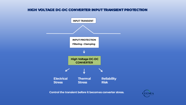
Industrial AC supplies can experience short-duration voltage transients caused by switching events, inductive loads, or disturbances on the upstream electrical network.
The front-end protection system may therefore need to provide a defined path for these abnormal events while protecting sensitive power-conversion components.
Depending on the application, protection may involve combinations of:
- Fuses or circuit protection
- Surge protection devices
- Input filters
- Controlled shutdown
- Voltage sensing
- Protection coordination
The exact protection strategy should be matched to the expected electrical environment and applicable requirements.
9.7 Short-Circuit and Downstream Faults
A downstream DC-DC converter or load can also develop a fault while the AC-DC front end is operating normally.
The front end should be designed so that a fault in one downstream power domain does not automatically create uncontrolled behavior throughout the complete power system.
For example:
AC-DC Front End → DC Bus → Multiple DC-DC Modules
If one downstream module experiences a short circuit, the protection strategy should determine whether the front end:
- Limits the available power
- Disconnects the affected bus
- Enters a controlled protection state
- Restarts after the fault is removed
The appropriate behavior depends on the system architecture and safety requirements.
9.8 Protection Should Be Coordinated Across Stages
Protection in a two-stage architecture should be considered as a hierarchy.
For example:
AC Input Protection
↓
AC-DC Front-End Protection
↓
DC-Bus Protection
↓
DC-DC Module Protection
↓
Load Protection
Each stage should have a clear purpose.
If every stage reacts to the same fault in an uncontrolled way, the system may experience nuisance shutdowns or repeated restart cycles.
Good protection coordination aims to isolate faults as locally as practical while maintaining the stability of unaffected power domains.
9.9 Startup and Protection Should Be Tested Together
Inrush and protection behavior are closely related.
A startup current that is perfectly normal for the DC-link can still be interpreted as a fault by an upstream circuit breaker or protection device if the system is not properly coordinated.
Likewise, repeated restart attempts can produce repeated inrush events and additional component stress.
The engineer should therefore evaluate:
Startup → DC-Bus Charging → Normal Operation → Fault → Shutdown → Restart
as one complete operating sequence.
9.10 Protection Affects the Complete Power Architecture
Protection is therefore not simply a set of components placed around the converter.
It influences:
- DC-bus capacitance
- Startup behavior
- PFC control
- Input protection
- Downstream converter behavior
- System recovery
- Reliability
For industrial AC-DC systems, a well-coordinated protection strategy should allow the converter to survive realistic electrical disturbances while avoiding unnecessary shutdowns during normal operation.
The practical principle is:
The front end should control not only how power enters the equipment, but also how the system behaves when the electrical conditions are no longer ideal.
10. When AC-DC + DC-DC Is the Better Architecture
An industrial power system does not always need a single AC-DC converter that directly generates every voltage required by the final loads.
In many cases, a two-stage architecture is more practical:
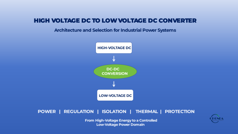
AC Input → AC-DC Front End → DC Bus → DC-DC Converter → Final Load
At first glance, adding a second conversion stage may appear less efficient than converting AC directly to the final DC voltage.
However, the additional stage can provide important architectural advantages when the equipment contains multiple voltage domains, requires galvanic isolation, has changing power requirements, or needs a controlled intermediate DC bus.
10.1 The AC-DC Stage and DC-DC Stage Can Have Different Jobs
The two conversion stages can be designed around different responsibilities.
The AC-DC front end can focus on:
- AC input compatibility
- Rectification
- PFC
- DC-bus formation
- Input protection
- Power quality
The downstream DC-DC stage can then focus on:
- Output-voltage conversion
- Galvanic isolation
- Precise regulation
- Multiple voltage domains
- Load-specific requirements
Dividing these functions can make the overall architecture easier to control.
Instead of asking one converter to solve every electrical problem simultaneously, each stage can be optimized for the role it performs.
10.2 A Common DC Bus Provides an Architectural Boundary
The DC bus acts as a stable interface between the AC side and the downstream DC power architecture.
For example:
AC Input → AC-DC → 400VDC Bus
Then:
400VDC Bus → Isolated DC-DC → 24V Control
and:
400VDC Bus → DC-DC → 12V Communication
The AC-DC stage therefore establishes the common energy source, while the individual DC-DC modules create the voltage and isolation conditions required by specific loads.
This becomes particularly useful when the system contains several different downstream power requirements.
10.3 Isolation Can Be Placed Where It Provides the Most Value
A two-stage architecture also allows engineers to choose where galvanic isolation should be introduced.
For example, the AC-DC stage may establish a common DC bus, while isolation is provided only by the downstream DC-DC converter serving a monitoring or control domain.
This can avoid designing the entire system around the most restrictive isolation requirement.
The architecture might therefore look like:
AC Input → AC-DC → HV DC Bus → Isolated DC-DC → Sensitive Load
while another load may use:
AC Input → AC-DC → HV DC Bus → Non-Isolated DC-DC → Control Load
This selective approach can make the overall system more flexible.
10.4 One AC-DC Stage Can Support Multiple DC-DC Modules
A major advantage of this architecture is that one front-end converter can establish a common DC bus for several downstream conversion stages.
For example:
AC Input
↓
AC-DC Front End
↓
Common DC Bus
↓
DC-DC Module A → Control
DC-DC Module B → Monitoring
DC-DC Module C → Communication
The downstream modules can then be selected according to the requirements of their specific power domains.
This architecture can be particularly attractive when the equipment is expected to evolve or when different product versions require different combinations of functions.
10.5 The Architecture Can Simplify Product Variations
Consider an industrial platform with a common AC input and DC bus.
The base product may require:
Control + Communication
A higher-end version may add:
Monitoring
An additional version may require:
Isolated Auxiliary Power
With a modular two-stage architecture, the common AC-DC front end can remain unchanged while the downstream DC-DC configuration changes.
This can reduce the need to redesign the entire front end whenever a new power domain is introduced.
10.6 The Additional Conversion Stage Has a Cost
The two-stage architecture is not automatically better.
Every conversion stage introduces additional:
- Power loss
- Components
- Thermal load
- Control complexity
- EMI sources
- Cost
The architecture should therefore be used only when the second stage provides a meaningful technical benefit.
If the equipment needs only one simple DC output and there is no strong requirement for intermediate bus control, isolation, or multiple voltage domains, a direct AC-DC solution may be more practical.
10.7 Efficiency Should Be Evaluated Across the Complete Power Path
The correct comparison is not:
Is one converter more efficient than two converters?
Instead, compare the complete system.
For example:
Direct Architecture
AC → AC-DC → Final Load
versus:
Two-Stage Architecture
AC → AC-DC → DC Bus → DC-DC → Final Load
The two-stage architecture may have an additional conversion loss, but it can also provide better regulation, isolation, load separation, or easier product scaling.
The system-level benefit may therefore outweigh the additional conversion loss.
10.8 When the Two-Stage Architecture Is Particularly Attractive
The AC-DC + DC-DC architecture becomes especially useful when the equipment requires several of the following:
- A controlled intermediate DC bus
- Multiple output-voltage domains
- Selective galvanic isolation
- Different downstream power levels
- High-voltage DC input to downstream modules
- Flexible product configurations
- Separate control and monitoring power domains
This is common in industrial equipment where the front end and downstream electronics have different electrical responsibilities.
10.9 A Typical Industrial Architecture
A practical example can be represented as:
AC Input
↓
AC-DC Front End
↓
High-Voltage DC Bus
↓
DC-DC Module A → 24V Control
DC-DC Module B → Isolated Monitoring
DC-DC Module C → Communication / Auxiliary
This architecture separates the major power-conversion functions while keeping the system connected through a common DC energy source.
The front end establishes the bus.
The downstream converters create the power domains.
The final loads then receive the voltage and isolation characteristics appropriate to their functions.
10.10 When Direct AC-DC Conversion May Be Better
A direct AC-DC architecture can still be the better choice when the system has:
- One main output voltage
- A relatively simple load
- Limited need for isolation
- No requirement for several voltage domains
- Low architectural complexity
- Tight cost constraints
Adding a DC-DC stage simply because it is technically possible can make the equipment more complicated without solving a real problem.
The best architecture depends on the requirements of the final system.
10.11 The Practical Architecture Decision
The engineering decision can therefore be summarized as:
AC → AC-DC → Load
is attractive when the power requirement is relatively direct and simple.
AC → AC-DC → DC Bus → DC-DC → Load
becomes more attractive when the system needs:
Multiple Voltage Domains + Selective Isolation + Controlled DC-Bus Architecture + Flexible Downstream Power Conversion
The additional stage should be justified by a clear system-level benefit.
The key principle is:
A two-stage AC-DC + DC-DC architecture is valuable when separating front-end power conversion from downstream power-domain conversion makes the complete industrial system easier to control, isolate, expand, or integrate.
This is why many industrial power systems do not end with the AC-DC stage. The AC-DC converter establishes the electrical foundation, while the downstream DC-DC converters turn that foundation into the specific power domains required by the equipment.
11. Common AC-DC Design Mistakes
Many AC-DC converter problems do not come from one incorrect component. They often come from an incomplete understanding of how the front end interacts with the rest of the industrial power system.
Before finalizing a design, it is useful to check a few common assumptions.
11.1 Designing Around Nominal Input Voltage Only
A converter that is designed only around the nominal AC voltage may not perform correctly at the minimum or maximum expected input condition.
The complete input envelope should include voltage range, frequency, phase configuration, and relevant transients.
11.2 Treating the DC Bus as a Fixed Voltage
The downstream DC-DC converter does not see only the nominal DC-bus value.
Ripple, transient response, startup behavior, and bus-voltage variation can all affect the input conditions seen by the downstream stage.
The AC-DC and DC-DC stages should therefore be designed as a compatible pair.
11.3 Adding PFC Without a System-Level Reason
PFC can improve input-current behavior, but it also adds another power-conversion stage and introduces additional components, losses, thermal load, and control complexity.
The decision should be based on the actual power level and input-power-quality requirements rather than on the assumption that a more complex front end is always better.
11.4 Underestimating Inrush Current
Large DC-link capacitors can create significant startup current.
Ignoring this condition can lead to nuisance trips, stressed components, or repeated startup problems.
Precharge and protection should therefore be considered during the initial architecture design.
11.5 Treating Isolation as a Single Number
An isolation-voltage rating does not fully describe the safety of an AC-DC converter.
Working voltage, transient conditions, creepage, clearance, insulation materials, and the complete physical construction must all be considered.
11.6 Checking Efficiency at Only One Operating Point
Maximum efficiency is not necessarily the efficiency that matters most in the real equipment.
Industrial systems should be evaluated at the input-voltage and load conditions they are expected to use most frequently.
11.7 Treating EMI as Only a Downstream DC-DC Problem
The AC-DC front end is directly connected to the external power network and can send conducted disturbances back toward the AC source.
Input-side filtering, PFC behavior, switching activity, and grounding should therefore be considered as part of the front-end architecture.
11.8 Designing the AC-DC Stage Independently from the Downstream Architecture
A front end may meet its own specification and still create unsuitable conditions for the downstream DC-DC stages.
The complete power path should be reviewed as:
AC Input → AC-DC Front End → DC Bus → DC-DC Conversion → Load
The best AC-DC design is therefore not simply one that satisfies its own datasheet requirements.
It is one that provides the right electrical foundation for the complete industrial power system.
Conclusion
Designing a high-voltage AC-DC converter for an industrial power system requires more than converting an AC input into a DC output.
The front end establishes the electrical foundation for the rest of the equipment, including the DC bus, downstream DC-DC converters, control systems, monitoring circuits, and other power domains.
A practical design should therefore consider the complete chain:
AC Input → Rectification → PFC / Front-End Control → DC Bus → Downstream DC-DC Conversion → Final Loads
The key design considerations include:
- AC input range and frequency
- Single-phase or three-phase operation
- Rectification and DC-bus formation
- Power factor and PFC
- Isolation and electrical safety
- DC-bus regulation and ripple
- Efficiency and thermal performance
- Input-side EMI
- Protection and inrush current
- Interaction with downstream DC-DC stages
The most important principle is that the AC-DC converter should not be designed as an isolated component.
Its input behavior, DC-bus characteristics, thermal performance, protection, and EMI should all be considered together with the requirements of the complete industrial power architecture.
For systems that require additional voltage conversion, isolation, or multiple power domains, an AC-DC + DC-DC architecture can provide greater flexibility than a single conversion stage when the additional complexity is justified by the application.
The goal is therefore not to choose the most sophisticated front end.
It is to create an AC-DC power stage that provides the right electrical foundation for the downstream power system while maintaining appropriate efficiency, thermal performance, safety, EMI, and reliability.
How CHONDA Supports Industrial AC-DC and DC-DC Power Architectures
CHONDA provides power modules and power-conversion solutions for industrial applications where AC-DC front-end conversion, downstream DC-DC conversion, isolation, and application-specific power requirements need to work together as one system.
Depending on the equipment architecture, this may include AC-DC front-end stages, high-voltage DC-DC modules, isolated power solutions, and customized electrical or mechanical configurations.
For industrial systems with non-standard input ranges, output requirements, isolation conditions, thermal environments, or space constraints, CHONDA can evaluate the complete power architecture and help determine whether a standard module, modified platform, or customized solution is appropriate.
The objective is not simply to supply an individual converter, but to support a power architecture that fits the electrical and integration requirements of the final equipment.
Related Articles
Choosing Between AC-DC and DC-DC Power Modules
Understand the key differences between AC-DC and DC-DC conversion and when each architecture is more appropriate for industrial power systems.
High Voltage Power Supply Design Guide
Explore a system-level framework for high-voltage power architecture, including power conversion, isolation, regulation, EMI, thermal management, protection, and power-module selection.
High Frequency DC-DC Converter Design: Efficiency & EMI
Learn how switching frequency affects magnetic size, switching losses, efficiency, thermal performance, EMI, and power density.
High Voltage DC-DC Converter Power Rating & Sizing
Learn how continuous power, peak load, efficiency, input range, thermal conditions, and design margin influence converter sizing.
High Voltage DC-DC Converter Thermal Management
Review temperature rise, cooling methods, thermal considerations, and derating for high-voltage DC-DC converter applications.
Modular High Voltage DC-DC Converters: Benefits & Applications
Explore modular power-conversion architectures and how multiple DC-DC modules can support different power domains in industrial equipment.