We help the world since 2012

High Voltage DC-DC Converter Thermal Bottlenecks: Where Does the Heat Go?
Thermal performance is often discussed in terms of temperature rise, cooling, or derating, but an important engineering question is sometimes overlooked:
Where does the heat actually go?
A high-voltage DC-DC converter generates heat at multiple points within the power-conversion stage. Semiconductor switching devices, magnetic components, rectification elements, capacitors, and other components may all contribute to the total power loss.
However, knowing how much heat is generated is only the beginning.
The more difficult question is whether that heat can travel effectively from the loss-generating component to the surrounding structure and ultimately to the environment.
A simplified thermal path can be understood as:
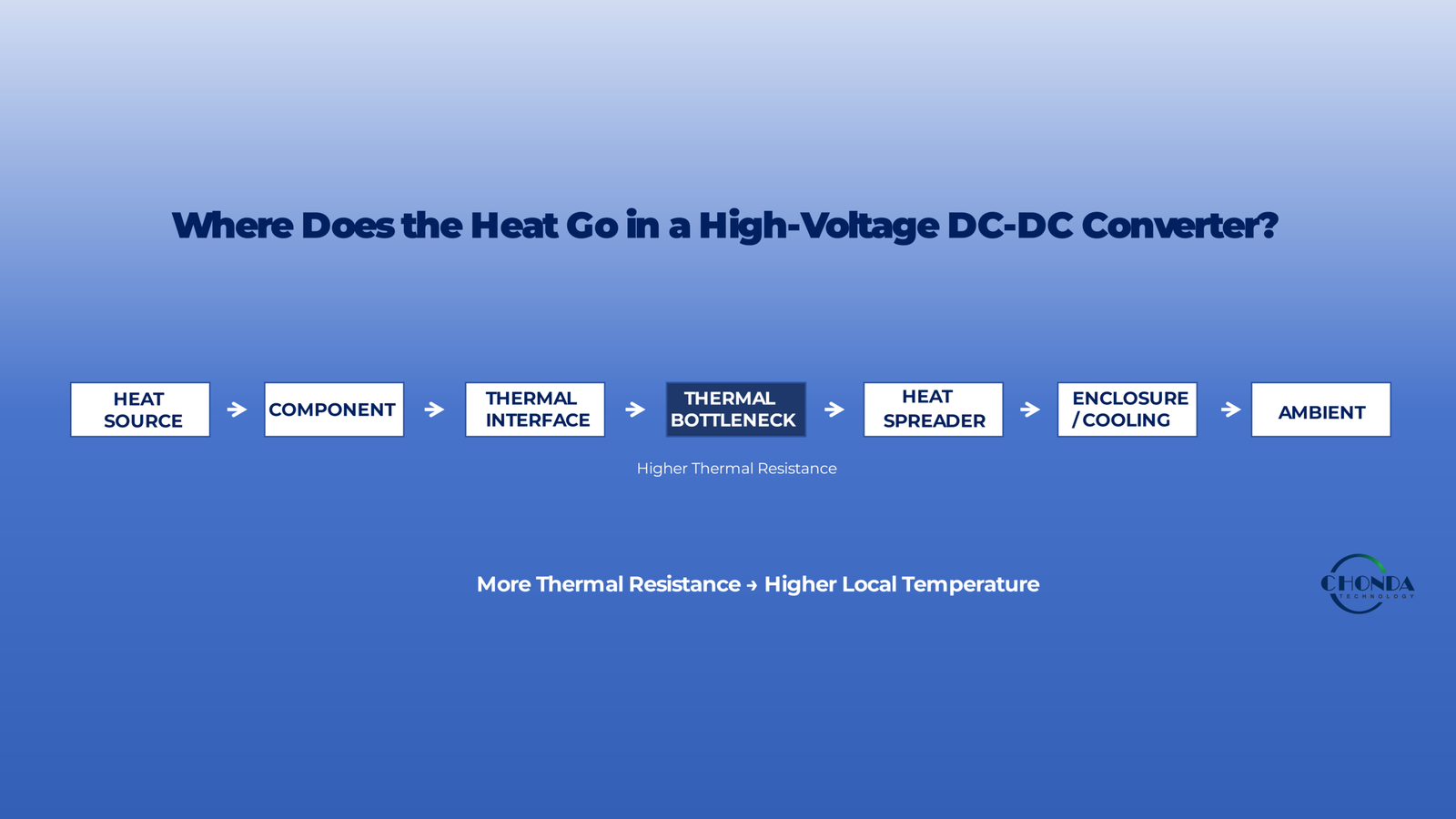
Power Loss → Component Temperature Rise → Thermal Path → Heat Spreading → Cooling Environment
If any part of this path becomes a bottleneck, the local component temperature may rise significantly even when the total converter power loss appears acceptable.
This is particularly important in compact high-voltage DC-DC converters, where higher power density can concentrate several heat-generating components within a limited physical volume.
For example, a converter may have acceptable total efficiency while one semiconductor, transformer winding, or rectifier reaches a much higher temperature than the rest of the system. In such cases, the limiting factor may not be total converter efficiency but the ability of a specific component and its surrounding structure to remove heat.
This guide examines where thermal bottlenecks can occur in high-voltage DC-DC converters, how heat moves through the power stage, and why component-level thermal paths can be just as important as the overall cooling method.
The focus is not simply on how to cool a converter.
It is on understanding where the heat is generated, how it travels, and where the thermal path becomes the limiting factor.
1. Where Does the Heat Come From?
Before identifying a thermal bottleneck, engineers first need to determine where the heat is being generated.
A high-voltage DC-DC converter does not produce heat at one single location. Power losses are distributed across the switching stage, magnetic components, rectification devices, capacitors, PCB structures, and other parts of the converter.
The total power loss may be relatively small compared with the output power, but the location of that loss can be just as important as its magnitude.
1.1 Semiconductor Switching Losses
Power semiconductors are often one of the most important heat sources in a high-frequency converter.
During switching transitions, voltage and current can overlap for a short period, creating switching losses. Conduction losses also occur while the device is carrying current.
As switching frequency, voltage, or current increases, the semiconductor loss behavior can change significantly.
This means that a converter with good overall efficiency may still have one switching device operating at a much higher temperature than other components.
The thermal problem is therefore not always:
“How much total heat does the converter produce?”
It may instead be:
“Which semiconductor is producing the heat, and how effectively can that heat leave the device?”
1.2 Transformer and Inductor Losses
Magnetic components are another important source of heat.
A transformer or inductor can experience both core loss and winding loss.
Core loss is influenced by factors such as frequency, flux density, magnetic material, temperature, and waveform.
Winding loss is affected by current, conductor resistance, frequency, and high-frequency current-distribution effects such as skin effect and proximity effect.
The physical location of these losses also matters.
Heat generated deep inside a magnetic structure may have a more difficult path to the outside of the component than heat generated close to a mounting surface.
A compact magnetic component can therefore have acceptable total loss while still developing a significant local temperature rise.
1.3 Rectification and Other Power Devices
Rectifiers, synchronous devices, diodes, and other power components can also contribute significant losses.
A device may dissipate heat through a combination of conduction loss and switching-related loss.
In some converter topologies, the rectification stage can become one of the dominant thermal sources, particularly when output current is high.
This creates an important design principle:
The component with the highest temperature is not necessarily the component with the highest total power loss.
Its thermal path may simply be less effective.
1.4 Capacitors and Passive Components
Capacitors can also generate heat when ripple current flows through their equivalent series resistance.
At high ripple current, even a relatively small effective resistance can produce measurable power dissipation.
Other passive components may also contribute losses through:
- Resistance
- Magnetic loss
- Dielectric loss
- Leakage-related loss
These losses are often smaller than the main switching losses, but their physical location can still matter if they occur in a compact or poorly cooled region.
1.5 PCB and Interconnection Losses
Power loss does not stop at the component package.
PCB copper, vias, connectors, bus structures, and other conductive paths also have resistance.
When current is high, these paths can contribute measurable conduction losses and local heating.
In a compact converter, a small hot region on the PCB can become a thermal bottleneck even when the overall board temperature appears acceptable.
This is particularly important where high-current paths are narrow, concentrated, or connected through thermal or mechanical structures that do not dissipate heat effectively.
1.6 Heat Sources Are Not Equally Important
The first step in thermal analysis is therefore not simply to add every loss together.
Engineers should identify:
Where is the loss generated?
How large is the loss?
How concentrated is the loss?
What thermal path does the heat have?
Two components may each dissipate 2W, but they may experience completely different temperatures if one has an efficient path into a heat sink while the other is surrounded by insulating material.
This is why thermal bottleneck analysis needs to consider both heat generation and heat transfer.
1.7 From Heat Source to Thermal Path
Once the major heat sources have been identified, the next question is how that heat travels.
For example:
Semiconductor Junction → Package → PCB / Heat Spreader → Enclosure → Ambient
or:
Transformer Winding → Insulation / Bobbin → Core → Mounting Structure → Cooling Environment
Each step introduces some thermal resistance.
If one part of the path is significantly more restrictive than the others, that location can become the thermal bottleneck.
Understanding this path is the foundation for determining where temperature rise is actually being created inside the converter.
2. Follow the Thermal Path: Where Does the Heat Actually Go?
Once the major heat sources have been identified, the next step is to follow the thermal path from the component generating the loss to the environment that ultimately absorbs the heat.
This is where many thermal problems become easier to understand.
A component does not become hot simply because it produces heat. It becomes hot when the heat it generates cannot leave quickly enough.
A simplified thermal path can be represented as:
Heat Source → Component Structure → Heat-Spreading Interface → Cooling Structure → Ambient
Every stage along this path affects the final component temperature.
2.1 The Hottest Component Is Not Always the Largest Heat Source
Consider two components that each dissipate approximately the same amount of power.
One is mounted directly onto a metal heat-spreading structure with a short thermal path.
The other is surrounded by electrically insulating material and has only a small contact area through which heat can escape.
The second component may operate at a much higher temperature even though its power loss is similar.
This is why thermal troubleshooting should not stop at:
“Which component is hottest?”
A more useful question is:
“Why is this component unable to remove its heat?”
That distinction can save significant time during thermal optimization.
2.2 Semiconductor Thermal Paths
For a power semiconductor, heat typically begins at the semiconductor junction and must travel through several physical layers before reaching the cooling environment.
A simplified path may be:
Junction → Package → PCB / Thermal Interface → Heat Spreader → Ambient
Each layer introduces some thermal resistance.
If the package transfers heat efficiently but the next interface is poorly designed, the interface can become the dominant thermal bottleneck.
For example, a device may have a low intrinsic thermal resistance, but if it is mounted on a limited copper area or connected to an inadequate heat-spreading structure, the system-level thermal performance may still be poor.
2.3 The PCB Can Be Part of the Heat Sink
In compact DC-DC converters, the PCB is often more than an electrical interconnection layer.
Copper areas, thermal vias, multiple PCB layers, and connections to external heat-spreading structures can all contribute to the thermal path.
A power device may transfer heat into the PCB, where the heat then spreads laterally before moving into another structure.
If the available copper area is too small, or if the thermal connection between layers is weak, the PCB itself can become a thermal bottleneck.
This is one reason why electrical layout and thermal design cannot always be treated as completely separate tasks.
2.4 Thermal Interfaces Can Become the Hidden Bottleneck
A thermal interface may appear mechanically simple, but it can have a major influence on the final temperature.
Examples include:
- Thermal pads
- Insulating sheets
- Thermal interface materials
- Mounting compounds
- Mechanical contact surfaces
The interface must sometimes provide both electrical insulation and thermal conduction.
These requirements can conflict.
A thicker insulating layer may improve voltage isolation while simultaneously increasing thermal resistance.
The engineer therefore needs to evaluate the electrical and thermal requirements together.
2.5 Magnetic Components Have Longer Thermal Paths
Transformers and inductors can have more complicated thermal paths than semiconductor devices.
Heat may be generated inside:
- Windings
- Core material
- Bobbin structures
- Internal insulation layers
The heat must then travel through several materials before reaching the outside surface.
For example:
Winding → Insulation → Bobbin → Core / Surface → Mounting Structure → Ambient
This becomes particularly important when the loss is concentrated inside the winding rather than near the outer surface.
A magnetic component can therefore look physically cool on the outside while a winding or internal region is operating at a much higher temperature.
2.6 The Thermal Bottleneck May Be Only One Small Section of the Path
A useful way to think about the thermal path is as a chain.
If most sections of the chain transfer heat efficiently but one section has much higher thermal resistance, that one section can dominate the temperature rise.
For example:
Component → PCB → Heat Spreader → Enclosure → Ambient
If the first two steps are well designed but the heat-spreading interface has poor thermal contact, improving the PCB may produce little additional benefit.
The bottleneck has to be found at the point where the heat flow is most restricted.
2.7 Temperature Rise Is a System Result
The final temperature of a component is therefore affected by several factors at the same time:
Power Loss + Thermal Resistance + Ambient Temperature
The same converter may show very different component temperatures under different installation conditions.
For example, a module operating in open air may remain within its expected temperature range, while the same module installed inside a sealed enclosure can experience significantly higher temperatures because the final part of the thermal path has become less effective.
This is why thermal measurements should be taken under representative installation conditions whenever possible.
2.8 Trace the Heat Before Changing the Cooling Method
When a converter runs too hot, the first reaction is often to add more cooling.
That may help, but it is not always the best first step.
A better diagnostic sequence is:
Identify the Hot Component
↓
Estimate Its Power Loss
↓
Trace Its Thermal Path
↓
Find the Highest-Resistance Section
↓
Improve That Section
Only after the actual bottleneck is understood should the engineer decide whether additional airflow, heat sinking, lower-loss components, a different interface material, or a revised mechanical structure is necessary.
This approach is often more effective than treating the entire converter as if it simply needs “more cooling.”
2.9 From Thermal Path to Thermal Bottleneck
The key idea is simple:
Heat follows a path, and temperature rises where that path becomes difficult.
For high-voltage DC-DC converters, the thermal bottleneck may exist in a semiconductor package, PCB structure, thermal interface, magnetic component, mounting surface, or the final path from the converter into the surrounding environment.
Finding the bottleneck is therefore often more useful than simply measuring the total heat generated by the converter.
The next step is to examine how thermal resistance is distributed along this path and why one seemingly small section can dominate the temperature rise of the entire power stage.
3. Thermal Resistance: Why One Small Bottleneck Can Dominate Temperature Rise
Once the thermal path has been identified, the next question is how effectively heat can move through each part of that path.
A useful engineering concept is thermal resistance.
Thermal resistance describes how much temperature difference is required to transfer a given amount of heat through a particular structure. In practical converter design, it helps engineers understand why a seemingly small interface or material layer can have a disproportionate effect on component temperature.
A simplified relationship is:
Temperature Rise = Power Loss × Thermal Resistance
The exact thermal model can become more complex in a real converter, but the basic idea is extremely useful for identifying thermal bottlenecks.
3.1 Thermal Resistance Exists Along the Entire Path
A component’s thermal path is normally made up of several stages.
For example:
Junction → Package → PCB → Thermal Interface → Heat Spreader → Ambient
Each stage contributes some thermal resistance.
The overall thermal behavior is therefore not determined by one number alone.
If most of the path has relatively low thermal resistance but one section has significantly higher resistance, that section can dominate the overall temperature rise.
This is why improving a component’s internal thermal characteristics may produce little benefit if the real limitation is somewhere further downstream.
3.2 A Small Interface Can Become a Large Bottleneck
Consider a power semiconductor mounted onto a heat-spreading structure.
The device may transfer heat efficiently into its package, and the heat spreader may have enough surface area to dissipate the heat into the environment.
However, if the interface between the device and the heat spreader is poorly designed, the heat can become trapped at that boundary.
This can happen because of:
- Excessive interface thickness
- Poor contact
- Inappropriate thermal interface material
- Limited contact area
- Required electrical insulation
In such cases, changing the heat sink may produce only a modest improvement because the thermal bottleneck is still located between the component and the heat-spreading structure.
3.3 Electrical Insulation and Thermal Conduction Can Conflict
High-voltage DC-DC converters often require electrical insulation between components and cooling structures.
This creates a common engineering trade-off.
An insulating layer may be necessary to satisfy the required electrical isolation, but some insulating materials conduct heat less effectively than metal or direct mechanical contact.
Increasing the thickness of the insulating layer may improve electrical insulation while simultaneously increasing thermal resistance.
The solution is therefore not simply to remove insulation.
Instead, engineers may need to find a structure or material that satisfies both:
Required Electrical Isolation
and
Acceptable Thermal Resistance
This is particularly important in isolated high-voltage converter designs.
3.4 Thermal Vias and Copper Area Are Part of the Path
When heat moves from a semiconductor into a PCB, copper area and thermal vias can influence how effectively the heat spreads.
A power device may be generating only a few watts of loss, but if the available copper area is small or the thermal connection between PCB layers is weak, the local temperature can rise significantly.
Increasing copper area or improving the thermal connection between layers can sometimes provide a greater benefit than adding a larger external heat sink.
The important question is where the heat is actually being restricted.
3.5 Magnetic Components Can Have Multiple Thermal Resistances
A transformer or inductor may contain several materials between the internal loss source and the surrounding environment.
For example:
Winding → Insulation → Bobbin → Core → Surface → Mounting Structure → Ambient
Each material has different thermal characteristics.
The winding may therefore operate at a significantly higher temperature than the visible outer surface of the magnetic component.
This is one reason temperature measurement alone can sometimes be misleading.
A surface measurement may look acceptable while the internal hot spot remains much higher.
3.6 Not All Thermal Resistance Is Fixed
Thermal resistance can also change with operating conditions.
The effective thermal behavior of a converter can be influenced by:
- Airflow
- Orientation
- Mounting method
- Ambient temperature
- Contact pressure
- Enclosure design
A converter mounted inside a sealed enclosure may therefore have a very different thermal path from the same converter tested on an open laboratory bench.
Thermal evaluation should match the real installation whenever possible.
3.7 Find the Dominant Thermal Resistance
When troubleshooting a hot converter, engineers do not necessarily need to improve every part of the thermal path.
A more efficient strategy is to identify the dominant thermal resistance first.
For example:
Junction → Package → PCB → Interface → Heat Spreader → Ambient
If the interface contributes most of the thermal resistance, increasing copper area elsewhere may have limited effect.
If the PCB is the limiting section, improving the external heat sink may again provide only a modest benefit.
The objective is to improve the section that actually controls the temperature rise.
3.8 Thermal Bottlenecks Can Shift as Power Increases
A converter may have one dominant thermal bottleneck at low power and another at higher power.
For example, at a moderate load, semiconductor temperature may be acceptable while the transformer remains relatively cool.
As load increases, winding loss and core loss may rise, causing the magnetic component to become the new limiting element.
Likewise, higher ambient temperature can shift the bottleneck because the final heat-transfer path to the environment becomes less effective.
Thermal analysis should therefore consider the operating range rather than relying on a single test point.
3.9 Thermal Design Is About the Complete Path
A useful engineering mindset is:
Do not ask only how much heat the component generates. Ask how much thermal resistance exists between the component and the environment.
This perspective changes the troubleshooting process.
Instead of immediately increasing cooling capacity, engineers can examine where temperature is being created and where heat transfer is being restricted.
For high-voltage DC-DC converters, understanding the distribution of thermal resistance is often the first step toward identifying the true thermal bottleneck.
The next step is to examine how thermal bottlenecks appear in different parts of the converter and how engineers can distinguish a component-loss problem from a heat-transfer problem.
4. Where Thermal Bottlenecks Commonly Appear
Thermal bottlenecks can appear in different parts of a high-voltage DC-DC converter, and the limiting point is not always obvious from the overall efficiency or total power loss.
A converter may have acceptable efficiency while one local component still operates at an excessive temperature.
This happens because thermal performance is determined not only by how much heat is generated, but also by where that heat is generated and how effectively it can move through the surrounding structure.
4.1 Semiconductor Junction to Cooling Structure
Power semiconductors are often closely associated with thermal problems because switching and conduction losses can be concentrated in a relatively small physical area.
Consider a simplified path:
Junction → Package → PCB / Thermal Interface → Heat Spreader → Ambient
If the semiconductor generates several watts of loss but the heat cannot spread efficiently beyond the package or PCB, the junction temperature can rise rapidly.
In this situation, the limiting factor may not be the semiconductor itself.
The bottleneck may instead be the connection between the package and the next thermal layer.
4.2 Transformer Windings
Magnetic components can create a different type of thermal bottleneck.
In a transformer, heat may be generated inside the winding through copper and high-frequency AC losses.
That heat then needs to travel through insulation, the bobbin, the magnetic structure, and finally to the external cooling environment.
The internal winding temperature can therefore be substantially higher than the measured surface temperature.
This becomes particularly important in compact high-frequency designs where the winding is tightly packed and the thermal path is relatively long.
A transformer can therefore become thermally limiting even when its total loss appears modest compared with the total converter power.
4.3 Transformer Core
The core itself can become a thermal bottleneck when core loss is concentrated within a relatively small magnetic volume.
As switching frequency or flux density increases, magnetic losses may rise.
The resulting heat must then travel through the core material and supporting structure before reaching the surrounding environment.
If the core has limited surface area or poor thermal contact with the mounting structure, the internal temperature may continue to rise even when external cooling appears adequate.
This is one reason why magnetic design and thermal design should be developed together.
4.4 PCB Thermal Spreading
The PCB can become the thermal bottleneck when high-loss components depend on copper planes and thermal vias to spread heat.
A power device may transfer heat efficiently into a copper area directly beneath it, but if that copper area is too small or poorly connected to lower PCB layers, the heat can accumulate locally.
The result can be a hot spot around the component even though the rest of the PCB remains relatively cool.
Increasing copper area, improving thermal-via density, or connecting the thermal region to a better heat-spreading structure can sometimes provide more benefit than increasing the external cooling capacity.
4.5 Thermal Interface Materials
Thermal interfaces deserve particular attention in high-voltage converters because electrical isolation may be required at the same location.
A thermal pad or insulating layer may provide the required dielectric separation while also forming an important part of the heat path.
If the material is too thick, has poor thermal conductivity, or has insufficient contact quality, it can become the dominant thermal resistance.
This creates a classic engineering trade-off:
Electrical Isolation Requirement ↔ Thermal Conductivity
The best solution is therefore not simply the thinnest possible interface, but an interface that satisfies the required insulation and thermal performance simultaneously.
4.6 Enclosure and Airflow
The final part of the thermal path is often the most underestimated.
A converter may successfully transfer heat from its internal components into the enclosure, but if the enclosure cannot release that heat efficiently, the internal temperature can continue to rise.
This can occur in:
- Sealed enclosures
- Small control cabinets
- High-density equipment
- Poorly ventilated compartments
- Systems with several adjacent heat sources
In such cases, the thermal bottleneck may not be inside the converter at all.
It may be the final step:
Converter → Enclosure → Surrounding Environment
4.7 Multiple Thermal Bottlenecks Can Exist at the Same Time
A real converter may have more than one limiting thermal path.
For example:
Semiconductor → PCB
may be limited by local heat spreading,
while:
Transformer → Enclosure
may be limited by the surrounding air temperature.
Improving one path may therefore reveal another bottleneck.
This is why thermal optimization is often an iterative process.
An improvement that reduces semiconductor temperature may expose the transformer as the next thermal limit.
4.8 The Bottleneck Can Move with Operating Conditions
Thermal bottlenecks are not necessarily fixed.
At light load, the semiconductor may be the dominant heat source.
At high load, winding loss may increase enough to make the transformer the limiting component.
At high ambient temperature, the final heat-transfer path to the environment may become the dominant limitation.
The thermal bottleneck can therefore change with:
Load + Frequency + Input Voltage + Ambient Temperature + Cooling Conditions
This is one reason why a single thermal test point is rarely sufficient to characterize a high-voltage DC-DC converter.
4.9 A Practical Way to Find the Bottleneck
When a converter runs hotter than expected, engineers can trace the thermal path from the hottest component outward.
For example:
Hot Component
↓
Where Is the Heat Generated?
↓
What Structure Receives the Heat?
↓
Where Does Heat-Spreading Slow Down?
↓
Where Does the Final Heat Transfer to Ambient Occur?
The limiting point is often the place where a large temperature difference appears over a relatively small physical distance.
Finding this point can be more useful than simply increasing airflow or installing a larger heat sink.
4.10 Thermal Bottleneck Analysis Is a System-Level Task
The thermal limit of a high-voltage DC-DC converter may therefore be determined by a very small part of the overall thermal path.
A semiconductor package, winding structure, PCB region, thermal interface, enclosure wall, or airflow condition can each become the limiting factor under different operating conditions.
The important engineering principle is:
Do not optimize the part that looks hottest until you understand why the heat cannot move beyond it.
Once the bottleneck is identified, engineers can decide whether the most effective solution is to reduce the loss source, improve the thermal path, change the interface, increase heat spreading, or improve the final cooling environment.
This distinction helps prevent thermal optimization from becoming a process of simply adding more cooling capacity without addressing the actual limiting mechanism.
5. Why Good Overall Efficiency Does Not Prevent Local Hot Spots
A high-voltage DC-DC converter can achieve good overall efficiency and still develop a localized thermal hot spot.
This may seem contradictory at first.
If a converter operates at 95% efficiency, for example, only a relatively small portion of the input power is lost. However, those losses are not necessarily distributed evenly across the entire converter.
A small amount of heat concentrated in one semiconductor, winding, connector, or PCB region can create a much higher local temperature than the average converter temperature suggests.
This distinction is important when evaluating thermal bottlenecks.
5.1 Total Loss and Local Loss Are Different Questions
Overall converter efficiency tells engineers how much input power is converted into useful output power and how much is lost.
For example, a 500W converter operating at 95% efficiency has approximately 25W of total power loss.
That 25W may sound manageable from a system-level perspective.
But if a significant portion of that loss is concentrated in one or two components, those components may still experience substantial temperature rise.
The thermal question therefore has two levels:
How much heat is generated in total?
and:
Where is that heat concentrated?
The second question is often the more important one when troubleshooting a hot component.
5.2 Distributed Loss Can Be Easier to Manage
Suppose the total converter loss is approximately 20W.
In one design, the loss may be distributed across several magnetic, semiconductor, and passive components.
In another design, a large part of the same 20W may be concentrated in a single switching device or transformer winding.
The second design can have a much more difficult thermal problem even though both converters have similar overall efficiency.
This is because the local temperature rise depends strongly on how much loss is generated within a particular physical region and how effectively that region can transfer heat away.
5.3 Power Density Changes the Picture
High power density makes local heating even more important.
As the converter becomes smaller, components are often placed closer together and the available thermal spreading area may become more limited.
The converter may therefore have:
Good Overall Efficiency + High Local Heat Density
This combination can produce hot spots that are not obvious from an efficiency figure alone.
For compact high-voltage DC-DC modules, thermal analysis should therefore consider both total loss and loss distribution.
5.4 A Small Component Can Become the Thermal Limit
A relatively small component can become the temperature-limiting element of the entire converter.
For example, a switching semiconductor may have a small physical footprint but experience high switching loss.
Likewise, a transformer winding may occupy only part of the magnetic structure while carrying significant high-frequency current.
In either case, the component’s temperature may reach its allowable limit before the rest of the converter appears thermally stressed.
This creates a common diagnostic situation:
The converter is not globally too hot, but one component is.
When this happens, improving the entire cooling system may not be the most effective solution.
The local thermal path should be investigated first.
5.5 Hot Spots Can Develop at Interfaces
Thermal hot spots can also appear at interfaces rather than at the main heat-generating component itself.
For example, heat may leave a semiconductor effectively but encounter a high thermal resistance at:
Package → Thermal Pad → Heat Spreader
The component may then operate at a much higher temperature than expected even though the external heat spreader remains relatively cool.
The same principle can apply to magnetic components, PCB structures, and enclosure interfaces.
A temperature difference across a small physical boundary can therefore reveal the location of a thermal bottleneck.
5.6 Average Temperature Can Hide a Local Problem
Measuring the average temperature of a converter enclosure can sometimes create a false sense of security.
The enclosure may feel moderately warm while an internal semiconductor junction or transformer winding is operating much closer to its maximum temperature.
Likewise, a PCB may show an acceptable average temperature while one small copper region around a power device becomes significantly hotter.
Thermal evaluation should therefore focus on the components and locations that actually limit reliability.
Depending on the design, engineers may use:
- Thermocouples
- Thermal cameras
- Temperature sensors
- Simulation
- Component-level thermal models
The measurement method should match the physical structure and the information required.
5.7 Efficiency Improvements Do Not Always Solve the Same Bottleneck
Reducing total converter loss can certainly improve thermal performance, but the improvement may not solve the dominant local problem.
For example, replacing one switching device with a lower-loss device may reduce total converter loss by several watts.
However, if another component has a poor thermal path, that component may remain the limiting temperature point.
This is why thermal optimization should distinguish between:
Loss Reduction
and:
Thermal Path Improvement
The most effective solution may require one or both.
5.8 A Better Thermal Troubleshooting Sequence
When a converter shows an unexpected hot spot, a useful sequence is:
Measure the Hot Spot
↓
Identify the Local Loss Source
↓
Estimate the Local Power Loss
↓
Trace the Thermal Path
↓
Identify the Dominant Thermal Resistance
↓
Decide: Reduce Loss or Improve Heat Transfer
This approach helps prevent engineers from immediately increasing the size of the heat sink without understanding the actual cause of the temperature rise.
5.9 The Key Engineering Principle
Overall efficiency remains an important system-level metric, but it should not be used as the only indicator of thermal performance.
A high-voltage DC-DC converter can have excellent overall efficiency and still fail thermally if one critical component develops excessive local temperature.
The practical question is therefore not only:
How efficient is the converter?
It is also:
Where are the losses concentrated, and how effectively can the heat leave those locations?
This distinction is central to identifying thermal bottlenecks in compact, high-power-density DC-DC converters.
6. Reduce the Heat Source or Improve the Thermal Path?
Once a thermal bottleneck has been identified, engineers usually have two broad options:
Reduce the amount of heat being generated
or
Improve the path through which the heat leaves the component.
Both approaches can reduce temperature, but they solve different problems.
The most effective solution depends on where the bottleneck actually exists.
6.1 When Reducing Power Loss Is the Better Solution
If a component is generating excessive heat because of high electrical loss, reducing that loss can be the most direct solution.
For example, excessive semiconductor temperature may be caused by:
- High switching loss
- High conduction loss
- Excessive current
- Inefficient operating conditions
- Unsuitable device selection
In such a case, improving the thermal interface without addressing the underlying power loss may only provide a limited improvement.
Reducing the loss source can lower the thermal load throughout the rest of the path.
For example:
Lower Switching Loss → Less Heat Generated → Lower Component Temperature
This can be particularly valuable when several components contribute to the overall thermal load.
6.2 When the Thermal Path Is the Real Problem
The opposite situation can also occur.
A component may generate a reasonable amount of heat, but the heat cannot leave efficiently.
For example:
Semiconductor → Thermal Interface → Heat Spreader
If the semiconductor loss is acceptable but the thermal interface has excessive resistance, improving the switching device itself may produce only a small change in temperature.
In this case, the more effective solution may be to:
- Improve the thermal interface
- Increase heat-spreading area
- Improve thermal-via structures
- Reduce interface thickness where electrically acceptable
- Improve mechanical contact
- Improve the connection to the cooling structure
The heat source has not changed.
The path has become more effective.
6.3 Some Problems Require Both Approaches
In a high-power-density converter, the thermal limitation may come from both the amount of heat generated and the ability to remove it.
For example, a high-frequency semiconductor may have relatively large switching losses while also being mounted through an electrically insulating thermal interface.
Reducing switching loss can lower the heat load.
Improving the thermal interface can then reduce the temperature rise caused by the remaining heat.
In such cases, the best result comes from:
Lower Loss + Better Thermal Path
rather than optimizing only one side.
6.4 Changing the Operating Point Can Solve a Thermal Problem
Thermal optimization does not always require changing a component.
Sometimes the operating conditions themselves are creating the bottleneck.
For example, engineers may reconsider:
- Switching frequency
- Output power
- Input-voltage operating point
- Switching speed
- Load distribution
A modest reduction in switching frequency may reduce semiconductor switching loss and magnetic loss.
Likewise, redistributing loads between modules may prevent one power stage from becoming the dominant thermal source.
This is one reason thermal analysis should be connected to the overall converter architecture rather than treated only as a cooling problem.
6.5 The Best Thermal Solution May Be Architectural
In a modular high-voltage DC-DC system, a thermal bottleneck may sometimes be solved by changing how power is distributed.
For example, if one converter module is carrying several unrelated loads, separating one high-loss or high-power function onto another module may reduce the thermal concentration in the original power stage.
The result is not simply:
“Cool the converter better.”
It becomes:
“Distribute the heat-generating functions more effectively.”
This can be particularly useful when mechanical space, airflow, or heat-spreading capacity is limited.
6.6 Do Not Automatically Add a Larger Heat Sink
Installing a larger heat sink is often an intuitive response to high temperature.
However, it may not solve the actual bottleneck.
If the dominant thermal resistance is:
Component → Interface
then increasing the size of the external heat sink may provide only a limited benefit.
Similarly, if the heat cannot spread effectively through the PCB, increasing airflow around the enclosure may have less impact than improving the PCB thermal path.
The correct sequence is:
Find the Bottleneck → Identify the Cause → Select the Appropriate Intervention
rather than:
Temperature High → Add More Cooling
6.7 Trade-Offs Must Be Considered
Thermal improvements can introduce new design constraints.
For example:
- A larger copper area may affect PCB layout.
- A thicker thermal interface may improve insulation but increase thermal resistance.
- A larger heat sink may increase mechanical size.
- Faster switching may reduce conduction-related effects but increase switching losses.
- A lower switching frequency may improve thermal performance but increase magnetic size.
This is why thermal engineering is rarely about optimizing one variable independently.
The objective is to improve the complete system without creating a more serious problem elsewhere.
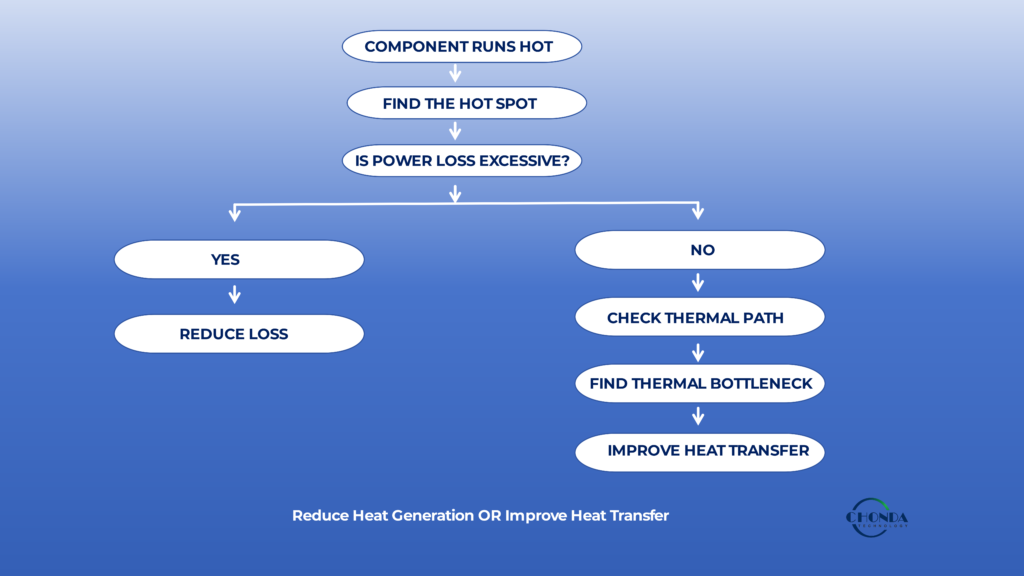
6.8 A Practical Thermal Decision Process
When a component is running hotter than expected, engineers can use a simple decision sequence:
Where Is the Hot Spot?
↓
How Much Power Is Being Lost There?
↓
Is the Loss Excessive?
YES → Reduce the Loss Source
NO → Examine the Thermal Path
↓
Where Is the Dominant Thermal Resistance?
↓
Improve the Bottleneck
↓
Recheck the Complete Operating Condition
This process helps distinguish between an electrical-loss problem and a heat-transfer problem.
6.9 Thermal Optimization Should Be Based on the Limiting Mechanism
The most important principle is:
Do not reduce heat where the heat is not the problem. Improve the thermal path where the path is the problem.
For high-voltage DC-DC converters, the correct solution may involve semiconductor selection, magnetic design, switching-frequency adjustment, PCB thermal spreading, interface materials, mechanical structure, airflow, or even a change in system architecture.
The best thermal improvement is therefore the one that addresses the actual limiting mechanism with the smallest overall impact on efficiency, EMI, mechanical size, cost, and reliability.
7. How to Identify a Thermal Bottleneck in a Real Converter
A thermal bottleneck is rarely identified from one temperature measurement alone.
In a real high-voltage DC-DC converter, engineers often need to combine temperature measurements, power-loss estimates, operating conditions, and knowledge of the physical thermal path to determine why one component is running hotter than expected.
The objective is not simply to find the hottest point.
It is to determine where the temperature rise is being created and which part of the thermal path is limiting heat transfer.
7.1 Start with the Hot Spot
The first step is to identify which component or physical region is operating at the highest temperature.
Depending on the converter design, this may be:
- A switching semiconductor
- A rectifier
- A transformer winding
- An inductor
- A capacitor
- A PCB copper region
- A connector or interconnection
- A thermal interface
The location of the hot spot provides the starting point for the thermal investigation.
However, the temperature itself does not explain the cause.
A hot component may be generating excessive loss, or it may simply have a poor thermal path.
7.2 Compare Temperature with Expected Power Loss
The next step is to estimate how much power is being dissipated at the hot component.
For example, suppose a semiconductor is operating at a noticeably higher temperature than the rest of the converter.
If its estimated loss is also unusually high, the first investigation should focus on the electrical causes of that loss.
If its loss appears reasonable but the temperature is still excessive, the thermal path becomes a more likely suspect.
This comparison helps distinguish between two very different problems:
Too Much Heat Generated
and
Heat Cannot Leave Efficiently
7.3 Trace the Physical Thermal Path
Once the hot component is identified, follow the physical path that the heat must travel.
For example:
Semiconductor Junction → Package → PCB → Thermal Via → Heat Spreader → Enclosure → Ambient
or:
Transformer Winding → Insulation → Core → Mounting Structure → Ambient
At each stage, ask:
What receives the heat next?
and:
Is that connection effective?
A large temperature difference concentrated across one small section of the path can be a strong indication that the section is acting as a thermal bottleneck.
7.4 Use Measurements to Find Temperature Differences
Different measurement methods can provide different information.
A thermal camera can help reveal:
- Hot spots
- Temperature distribution
- Local heat spreading
- Unexpected heating around interfaces
Thermocouples or embedded temperature sensors can provide more targeted measurements at specific locations.
For some components, however, surface temperature does not represent the internal temperature accurately.
This is particularly important for magnetic components, semiconductor junctions, and structures where the actual heat source is located inside the component.
Measurement results should therefore always be interpreted with the physical thermal path in mind.
7.5 Test at More Than One Operating Point
A thermal bottleneck may not be visible at one operating condition.
For example, a converter may operate normally at moderate load but develop a transformer hot spot near full load.
Another design may show acceptable thermal performance at room temperature but become limited when the ambient temperature rises.
Useful test points may include:
Low Load → Typical Load → High Load → Peak Condition
and, where appropriate:
Low Ambient → Normal Ambient → High Ambient
Comparing the same component across these conditions can reveal how the bottleneck changes as the system operating point changes.
7.6 Look for the Temperature That Rises Disproportionately
One useful diagnostic clue is a component whose temperature increases much faster than the overall converter temperature as load rises.
For example:
- Converter load increases by 20%
- Most component temperatures rise moderately
- One transformer winding temperature rises sharply
This can indicate that the component is approaching a thermal limitation or that its loss mechanism is becoming increasingly significant.
A disproportionately rising temperature is often more informative than simply knowing which component is hottest at one fixed load.
7.7 Distinguish Loss Increase from Path Degradation
Temperature can increase for two very different reasons.
The first is that the component is generating more heat.
The second is that the thermal path has become less effective.
For example, increasing load may increase semiconductor loss.
By contrast, poor mechanical contact, an unsuitable interface material, or a restricted airflow path can increase temperature without changing the electrical loss very much.
The engineer should therefore compare both:
Electrical Loss
and
Thermal Transfer
rather than assuming that every temperature increase is caused by higher power consumption.
7.8 Verify the Finding with a Targeted Change
Once a likely bottleneck has been identified, a controlled design change can help confirm the diagnosis.
For example:
- Increase local copper area
- Improve thermal-via connection
- Change the thermal interface
- Improve mechanical contact
- Reduce switching loss
- Reduce magnetic loss
- Improve airflow around the affected area
If the expected component temperature changes significantly after the targeted modification, the original diagnosis becomes more credible.
This is often more useful than making several changes simultaneously, because multiple changes can make it difficult to determine which modification actually solved the problem.
7.9 Thermal Troubleshooting Should Follow a Chain
A practical diagnostic sequence is:
Hot Spot
↓
Power Loss
↓
Thermal Path
↓
Dominant Thermal Resistance
↓
Targeted Improvement
↓
Re-Test
This process turns thermal troubleshooting from a trial-and-error exercise into a structured engineering investigation.
7.10 A Thermal Bottleneck Is a Design Clue
Finding a thermal bottleneck should not only be viewed as a failure to meet a temperature target.
It can also reveal something about the converter architecture.
For example, repeated overheating of one magnetic component may indicate:
- Excessive flux density
- High winding loss
- Poor magnetic construction
- Insufficient heat spreading
- An overly compact mechanical design
Likewise, repeated semiconductor hot spots may indicate that switching losses, package thermal resistance, PCB structure, or switching conditions need to be reconsidered.
A thermal bottleneck therefore provides information about where the underlying design may need improvement.
The most useful thermal analysis does not stop at identifying the hottest component.
It explains why that component is hot, where the heat is being blocked, and which design change will address the actual limiting mechanism.
8. How to Improve a Thermal Bottleneck
Once the thermal bottleneck has been identified, the next step is to determine which design change will provide the greatest temperature reduction without creating new problems elsewhere in the converter.
There is no single thermal solution that works for every high-voltage DC-DC converter.
The appropriate improvement depends on whether the limiting mechanism is excessive power loss, poor heat spreading, high thermal resistance, insufficient cooling, or a combination of several factors.
8.1 Reduce the Loss at the Source
If the thermal investigation shows that too much heat is being generated by a particular component, reducing the loss at its source is often the most direct solution.
For a semiconductor, this may involve reducing:
- Switching loss
- Conduction loss
- Gate-drive loss
- Excessive current stress
For a magnetic component, the focus may instead be on:
- Core loss
- Winding loss
- Flux density
- Switching frequency
- Magnetic material
Reducing the loss source has a system-wide advantage because less heat enters the thermal path in the first place.
8.2 Improve the Local Heat-Spreading Path
If the component loss is reasonable but the temperature remains high, the thermal path may need to be improved.
For a PCB-mounted power device, this could involve increasing the effective copper area or improving the connection between PCB layers.
For a mechanically mounted component, it could involve improving contact with the heat-spreading structure.
The most useful modification is usually the one closest to the actual thermal bottleneck.
8.3 Improve the Thermal Interface
Interfaces can have a surprisingly large influence on thermal performance.
Depending on the structure, engineers may evaluate:
- Thermal interface material
- Interface thickness
- Contact quality
- Contact area
- Clamping or mounting pressure
- Electrical insulation requirements
The correct solution must satisfy both thermal and electrical requirements.
For a high-voltage converter, reducing thermal resistance cannot come at the expense of the insulation system required by the application.
8.4 Improve PCB Thermal Spreading
When the PCB is part of the thermal path, thermal spreading can sometimes be improved without changing the main power device.
For example, engineers may optimize:
- Copper area
- Thermal vias
- Layer connections
- Heat-spreading regions
- Connections to external cooling structures
The objective is to move heat away from the hot region before it accumulates locally.
This is particularly important in compact converters where the PCB may carry both electrical current and thermal load.
8.5 Reconsider Magnetic Construction
If the thermal bottleneck is inside a transformer or inductor, changing the external cooling alone may not solve the problem.
The internal loss mechanism may need to be addressed.
Possible areas of investigation include:
- Core material
- Flux density
- Winding structure
- Conductor selection
- Skin effect
- Proximity effect
- Winding window utilization
- Thermal path from the winding to the external structure
A magnetic component can therefore require both electrical optimization and thermal optimization.
8.6 Reconsider Switching Frequency
In a high-frequency converter, switching frequency can influence both the size of the magnetic components and the amount of heat they generate.
If the thermal bottleneck is strongly related to switching loss or magnetic loss, reducing the switching frequency may improve thermal performance.
The trade-off is that the transformer, inductor, or filter components may become larger.
The right question is therefore not:
Can the converter operate at a higher frequency?
It is:
Does the additional frequency provide enough system-level benefit to justify the resulting thermal cost?
8.7 Improve the Final Heat-Rejection Path
If the internal thermal paths are already effective but the heat cannot ultimately leave the equipment, the final stage of the thermal path may need to be improved.
Possible changes include:
- Better airflow
- Improved enclosure ventilation
- Heat sinks
- Heat spreaders
- Mechanical mounting changes
- Improved connection to the equipment chassis
However, these changes are most effective when the internal thermal path has already been evaluated.
There is little benefit in increasing external cooling capacity if the dominant bottleneck is still located close to the heat-generating component.
8.8 Consider a Different Component or Architecture
Sometimes the thermal bottleneck reveals that the original architecture itself is approaching its practical limit.
For example, a single module may be carrying several high-power functions that create excessive local heat concentration.
A modular redesign could distribute these functions across separate power stages.
Likewise, changing the semiconductor technology, converter topology, or magnetic architecture may reduce losses sufficiently to solve the thermal problem without adding more cooling hardware.
Thermal analysis can therefore lead to an electrical or architectural redesign rather than only a mechanical cooling change.
8.9 Improve One Bottleneck at a Time
During thermal optimization, it is useful to make targeted changes whenever practical.
For example:
Identify Bottleneck
↓
Change One Relevant Design Factor
↓
Measure the Temperature Again
↓
Confirm the Expected Improvement
This makes it easier to determine whether the proposed solution actually addressed the dominant thermal resistance or loss mechanism.
Changing several unrelated variables simultaneously can make the result difficult to interpret.
8.10 Recheck the Complete Converter
A successful local thermal improvement should not be considered the final result until the complete converter has been reviewed again.
An improvement in one area can sometimes create a new limitation elsewhere.
For example:
- Reducing switching frequency may increase magnetic size.
- Increasing copper area may affect PCB spacing.
- Changing a thermal interface may affect isolation.
- Increasing airflow may change enclosure design.
- Redistributing loads may change the modular power architecture.
Thermal optimization therefore needs to be treated as part of the overall converter design.
8.11 The Most Effective Thermal Improvement
A practical decision process can be summarized as:
Find the Bottleneck → Identify the Cause → Reduce Loss or Improve the Thermal Path → Re-Test → Check the Complete System
The most effective solution is usually the one that addresses the actual limiting mechanism rather than simply increasing cooling capacity.
For high-voltage DC-DC converters, thermal performance improves most reliably when loss generation, component construction, thermal paths, and system cooling are considered together.
9. How Thermal Bottlenecks Affect Converter Design
A thermal bottleneck is rarely an isolated thermal problem.
Once a component reaches its practical temperature limit, the thermal constraint can begin to influence other parts of the converter design, including switching frequency, power density, component selection, mechanical structure, and even the overall power architecture.
This is why thermal analysis should be performed early enough to influence the design rather than being treated only as a final verification step.
9.1 Thermal Limits Can Restrict Power Density
A converter may be electrically capable of delivering more power, but its usable power density may be limited by the ability to remove heat from critical components.
For example, reducing transformer volume may allow a smaller converter enclosure, but if the smaller magnetic structure cannot dissipate its losses effectively, the practical continuous power may become limited by temperature.
This creates an important distinction:
Electrical Power Capability ≠ Thermally Usable Power Capability
The converter may have sufficient electrical capacity while still requiring derating because of a thermal bottleneck.
9.2 Thermal Bottlenecks Can Influence Switching Frequency
In a high-frequency converter, the switching frequency affects both magnetic size and power loss.
If thermal analysis shows that switching losses or magnetic losses are already limiting the design, increasing switching frequency further may reduce component size while making the thermal problem worse.
In such a case, a lower switching frequency may provide a better overall solution even if the transformer or inductor becomes larger.
This is one reason frequency selection should be evaluated together with thermal performance.
9.3 Thermal Limits Can Influence Component Selection
A component should not be selected only because it satisfies voltage and current requirements.
The thermal environment also matters.
For example, two semiconductor devices may have similar electrical ratings but different switching characteristics, conduction losses, or thermal performance.
Likewise, two magnetic materials may satisfy the same basic electrical function while producing different losses at the intended operating frequency and flux density.
Thermal analysis can therefore become an important part of selecting the most suitable component technology.
9.4 Thermal Bottlenecks Can Limit Compact Packaging
Compact packaging often places components closer together and reduces the available space for heat spreading.
This can create a situation where the electrical design works well but the mechanical packaging becomes the limiting factor.
The engineering team may then need to choose between:
Smaller Size
and:
Lower Thermal Density
The better solution depends on the actual system requirement.
For equipment with strict enclosure constraints, a higher level of thermal optimization may justify the additional design effort.
9.5 Thermal Problems Can Reveal an Architecture Problem
Sometimes the thermal bottleneck is a symptom of an architectural decision rather than a component-level problem.
For example, one converter module may be responsible for several unrelated high-power functions.
Even if the converter is well designed, concentrating these functions in one power stage may create a difficult local thermal environment.
A modular architecture could distribute the power-conversion functions across separate modules.
This does not automatically improve efficiency, but it may provide better thermal distribution and make the overall system easier to manage.
Thermal analysis can therefore reveal opportunities to reconsider the architecture rather than simply adding larger cooling hardware.
9.6 Thermal Constraints and Reliability
Temperature is also closely related to long-term component reliability.
Components exposed to elevated temperatures may experience greater thermal stress over time.
This makes thermal bottleneck analysis important not only for meeting an immediate temperature specification, but also for maintaining stable long-term operation.
A design that technically remains below its maximum temperature may still benefit from additional thermal margin if the equipment is expected to operate continuously under demanding conditions.
9.7 Thermal Bottlenecks Can Change During Product Evolution
A converter that performs well in a first-generation product may develop a new thermal limitation when the system is upgraded.
For example:
- Output power may increase.
- The enclosure may become smaller.
- Additional functions may be added.
- Ambient temperature may increase.
- Cooling airflow may change.
A thermal path that was previously adequate may then become the new bottleneck.
This is another reason why modular and scalable power architectures can be useful: they can make it easier to redistribute or separate functions when system requirements change.
9.8 Thermal Analysis Should Influence Design Early
The most effective thermal design process begins before the final prototype is complete.
Engineers can use estimated losses, thermal models, component data, and representative operating conditions to identify possible bottlenecks early.
This allows the design team to adjust:
Component Selection → Magnetic Design → Switching Frequency → PCB Structure → Mechanical Packaging → Cooling
before late-stage thermal problems become expensive to correct.
9.9 Thermal Bottleneck as a Design Decision Tool
A useful way to think about thermal bottlenecks is that they provide information about the true limits of a converter.
If the main limitation is:
Semiconductor Loss
→ reconsider switching conditions or device selection.
If it is:
Magnetic Loss
→ reconsider frequency, flux density, core material, or winding construction.
If it is:
Thermal Interface
→ improve the local heat path.
If it is:
Enclosure / Ambient
→ improve heat rejection or reconsider system packaging.
If it is:
Excessive Power Concentration
→ consider redistributing the conversion functions.
The thermal bottleneck therefore becomes a decision point for the next design improvement.
9.10 Thermal Design Should Follow the Limiting Mechanism
The central engineering principle is:
The thermal limit of a converter should guide the design change, rather than the design change being chosen before the thermal limit is understood.
Once the actual bottleneck is known, engineers can make a more informed decision about whether to reduce losses, improve the thermal path, change the operating point, modify the package, redistribute power, or reconsider the architecture.
This approach avoids treating thermal design as simply an exercise in adding heat sinks and instead makes it part of the broader engineering optimization of the high-voltage DC-DC converter.
10. Thermal Bottlenecks in Real-World High-Voltage DC-DC Applications
The importance of a thermal bottleneck depends strongly on how the converter is used.
A temperature rise that is acceptable in a short-duration application may become a reliability concern in equipment that operates continuously at high ambient temperature.
For this reason, thermal analysis should be based on the actual application, load profile, installation environment, and expected operating lifetime.
10.1 PV Monitoring Applications
PV monitoring equipment can require auxiliary power conversion from a relatively high-voltage DC source while operating continuously for long periods.
In this type of application, the converter may have a modest output power but still face demanding thermal conditions because the equipment can remain energized for extended periods.
A small local loss in a semiconductor, transformer, or rectifier may therefore become significant over time.
The physical installation also matters.
A converter placed inside a compact monitoring enclosure may have a very different thermal environment from the same converter tested in open air.
For this reason, the thermal path should be evaluated from the power-conversion component all the way to the actual enclosure and surrounding environment.
10.2 Battery Energy Storage Systems
Battery energy storage systems can expose auxiliary DC-DC converters to high-voltage DC buses, variable operating conditions, and elevated ambient temperatures.
Different power domains may also operate simultaneously, which can create several local heat sources within a confined enclosure.
A converter that appears thermally acceptable when tested independently may therefore experience a higher local ambient temperature after being installed close to other heat-generating components.
In BESS applications, thermal analysis should consider not only the converter’s own losses but also the combined thermal environment created by nearby power electronics.
10.3 Industrial Automation Equipment
Industrial automation equipment may operate continuously in control cabinets or enclosed machinery where airflow is limited.
The converter may supply control electronics, sensors, communication interfaces, or other auxiliary loads.
A thermal bottleneck can develop at a local PCB region, semiconductor package, connector, or thermal interface even when the overall cabinet temperature appears acceptable.
This is particularly relevant when the equipment is expected to operate reliably for long periods without service intervention.
The thermal design should therefore be evaluated under the actual cabinet conditions rather than under ideal laboratory conditions.
10.4 Robotics and Embedded Power Systems
Robotic and embedded systems often place strict limits on size and weight.
High power density can therefore be valuable, but compact packaging also leaves less room for heat spreading and cooling.
A small converter may have excellent electrical performance while becoming thermally limited because several loss-generating components are concentrated within a restricted volume.
In such systems, the design may require a balance between:
Compact Size + Power Density
and:
Thermal Margin + Reliability
The thermal bottleneck can therefore influence not only component selection but also the physical placement of the power module within the equipment.
10.5 High-Voltage Industrial Power Modules
High-voltage DC-DC modules may also be used as building blocks within larger power architectures.
In these applications, the thermal behavior of the module depends partly on how it is integrated.
The same module may operate under different thermal conditions depending on:
- Mounting structure
- PCB or chassis connection
- Enclosure size
- Nearby heat sources
- Airflow
- Continuous load
This means that a module’s thermal capability should be evaluated together with the final installation rather than treated as an entirely independent product characteristic.
10.6 Why Continuous Operation Matters
Thermal bottlenecks become particularly important when the converter operates continuously near its normal power level.
A short-duration temperature increase may be acceptable during a transient event.
A similar temperature rise that occurs continuously can produce a very different long-term reliability condition.
This is why application analysis should distinguish between:
Short-Term Peak Heating
and:
Continuous Thermal Stress
The duty cycle of the equipment can therefore be just as important as its maximum electrical power.
10.7 The Application Can Change the Bottleneck
The same converter may have different thermal limits in different applications.
For example, the limiting component may be the transformer in one application and a semiconductor in another.
The difference may come from:
- Load profile
- Ambient temperature
- Input voltage
- Switching frequency
- Cooling structure
- Installation orientation
- Enclosure conditions
Thermal performance should therefore be evaluated in the context of the final application rather than by assuming that one test result represents every installation.
10.8 A Practical Application-Level Thermal Review
Before finalizing a high-voltage DC-DC converter for a real application, engineers can review:
Where is the heat generated?
How long does the equipment operate under that condition?
Where does the heat go?
What is the final cooling environment?
Which component is likely to become the thermal limit?
Does the design still have adequate thermal margin at maximum ambient temperature?
These questions help connect component-level thermal analysis with the real operating environment of the equipment.
10.9 CHONDA Applications and Thermal Integration
For CHONDA power-module applications, thermal evaluation is especially important when a standard or customized module is integrated into compact industrial equipment.
Applications such as PV monitoring, industrial automation, robotics, and other high-voltage DC systems may have very different enclosure, load, airflow, and ambient-temperature conditions.
A suitable power module therefore needs to be considered not only for its electrical specifications but also for how its thermal path fits into the final equipment.
Where the application has unusual thermal, mechanical, input-voltage, isolation, or power requirements, the thermal analysis can also become part of the decision between a standard module, modified platform, or customized power solution.
The key principle is:
Thermal performance belongs to the complete application, not only to the converter datasheet.
11. A Practical Thermal Bottleneck Review
Identifying a thermal bottleneck does not need to begin with a complicated thermal model.
A structured review of the converter’s power losses, physical thermal paths, operating conditions, and temperature distribution can often reveal where the design is being limited.
The purpose of the review is not simply to determine whether the converter is hot.
It is to understand why a particular component or region becomes hot and what is limiting the movement of heat.
11.1 Start with the Operating Condition
Before examining individual components, define the condition under which the thermal problem occurs.
Consider:
- Input voltage
- Output power
- Load profile
- Switching frequency
- Ambient temperature
- Cooling conditions
- Enclosure configuration
A thermal measurement without its corresponding electrical and environmental conditions is difficult to interpret.
11.2 Identify the Main Heat Sources
Next, identify where the converter is generating most of its losses.
Typical sources include semiconductor switching and conduction losses, transformer and inductor losses, rectification losses, capacitor ripple losses, and high-current PCB or interconnection losses.
The objective is not to calculate every loss to the same level of detail immediately.
It is to determine which components are likely to contribute meaningfully to the thermal load.
11.3 Locate the Hot Spots
Use measurements, simulation, or both to identify the components or physical areas with the highest temperature.
Then compare the hot spots with the estimated loss sources.
A component with high loss and high temperature may be limited by both electrical loss and thermal resistance.
A component with moderate loss but unusually high temperature may indicate a thermal-path problem.
This comparison provides a useful first indication of where to investigate.
11.4 Trace the Thermal Path
For each important heat source, follow the physical path to the environment.
For example:
Semiconductor → Package → PCB → Thermal Interface → Heat Spreader → Ambient
or:
Transformer Winding → Insulation → Core → Mounting Structure → Ambient
At each step, ask:
Is this section transferring heat effectively?
A significant temperature difference across one part of the path can indicate a potential bottleneck.
11.5 Separate Loss Problems from Heat-Transfer Problems
At this point, determine whether the dominant problem is:
Too Much Heat Generation
or:
Insufficient Heat Transfer
If the component loss is excessive, reducing switching, conduction, or magnetic losses may be the most effective solution.
If the loss is reasonable but the temperature remains high, improving the thermal path may provide greater benefit.
This distinction prevents engineers from applying the wrong solution to the wrong problem.
11.6 Check the Worst-Case Condition
A thermal bottleneck should be evaluated under the conditions that are most demanding for the real application.
This may include:
Maximum Expected Load
Maximum Ambient Temperature
Relevant Input-Voltage Condition
Actual Cooling Environment
The worst thermal condition is not always the maximum electrical power condition alone.
For example, a lower input voltage may increase input current and conduction loss, while a restricted enclosure may prevent heat from leaving efficiently.
11.7 Make a Targeted Design Change
Once the limiting mechanism has been identified, choose a modification that directly addresses it.
For example:
Excessive Semiconductor Loss
→ Reconsider device selection or switching conditions.
High Winding Loss
→ Reconsider conductor structure, frequency, or magnetic design.
PCB Thermal Bottleneck
→ Improve copper spreading or thermal-via structure.
Poor Thermal Interface
→ Improve the interface while maintaining required electrical insulation.
Enclosure Heat-Rejection Problem
→ Improve heat spreading, airflow, or mechanical integration.
Excessive Power Concentration
→ Consider redistributing functions across power modules.
A targeted change is more useful than making several unrelated modifications at once.
11.8 Re-Test the Complete System
After the thermal improvement, repeat the measurement under the same representative operating conditions.
The goal is not only to confirm that the original hot spot has become cooler.
Engineers should also check whether the modification has created a new limitation elsewhere.
For example, improving semiconductor cooling may reveal the transformer as the next thermal limit.
Thermal optimization is therefore an iterative process:
Identify → Modify → Measure → Re-Evaluate
11.9 Record the Thermal Path as Part of the Design
For products that will be manufactured repeatedly, the thermal path should be treated as part of the design definition rather than as an informal prototype detail.
Relevant information may include:
- Heat-generating components
- Thermal interfaces
- PCB thermal structures
- Mounting surfaces
- Cooling conditions
- Temperature limits
- Derating assumptions
This helps ensure that the thermal behavior observed during development can be reproduced in production.
11.10 A Practical Thermal Bottleneck Checklist
Before finalizing a high-voltage DC-DC converter, engineers should be able to answer:
Where is the heat generated?
Which component has the highest local temperature?
How much power is being lost there?
What is the thermal path from that component to the environment?
Where is the dominant thermal resistance?
Is the problem caused by excessive loss or poor heat transfer?
Does the design remain acceptable at maximum realistic ambient temperature?
Could a local improvement create a new bottleneck elsewhere?
If these questions can be answered with confidence, the thermal design has moved beyond simply measuring temperatures and toward understanding the actual thermal behavior of the converter.
11.11 The Thermal Bottleneck Review in One Process
The complete approach can be summarized as:
Operating Condition
↓
Heat Sources
↓
Hot Spots
↓
Thermal Path
↓
Thermal Bottleneck
↓
Loss Reduction or Thermal-Path Improvement
↓
Re-Test
↓
System-Level Verification
This process helps engineers move from “the converter is running hot” to a much more useful engineering conclusion:
“This is the limiting thermal mechanism, and this is the design change that addresses it.”
Conclusion
Thermal performance in a high-voltage DC-DC converter is not determined by efficiency alone.
A converter can have acceptable overall efficiency and still develop a critical hot spot if heat is concentrated in a sensitive component or if the thermal path contains a significant bottleneck.
A practical thermal analysis should therefore follow the complete path:
Heat Source → Thermal Path → Thermal Resistance → Thermal Bottleneck → Design Improvement
The key questions are not simply:
How much heat does the converter generate?
but also:
Where is the heat generated?
and:
Where does the heat stop moving effectively?
This distinction is particularly important in compact, high-power-density converters where semiconductor losses, magnetic losses, PCB structures, thermal interfaces, and enclosure conditions all interact.
When a thermal bottleneck is identified, the solution may involve reducing the loss source, improving the local thermal path, changing the operating point, improving heat spreading, modifying the mechanical structure, or redistributing power across different modules.
The most effective thermal design is therefore not the one with the largest heat sink.
It is the one that addresses the actual limiting thermal mechanism while maintaining the required efficiency, EMI performance, electrical isolation, mechanical integration, and long-term reliability.
For industrial applications such as PV monitoring, battery energy storage, robotics, industrial automation, and embedded power systems, understanding where heat is generated and how it travels through the converter can provide a stronger basis for reliable high-voltage DC-DC design.
How CHONDA Approaches Thermal Considerations
For CHONDA high-voltage DC-DC power-module applications, thermal evaluation is considered together with input voltage, output power, switching conditions, isolation, mechanical integration, and the actual installation environment.
Standard, modified, or customized power solutions may require different thermal approaches depending on the power level, enclosure, cooling conditions, and application requirements.
The objective is to achieve a power-conversion solution in which the electrical design and thermal path work together under the real operating conditions of the final equipment.
Related Articles
High Voltage DC-DC Converter Thermal Management
Explore temperature rise, cooling methods, derating, thermal design, and reliability considerations for high-voltage DC-DC converters.
High Voltage Power Supply Design Guide
Review a system-level approach to high-voltage power-supply architecture, including thermal management, EMI, isolation, protection, PCB design, and power-module selection.
High Frequency DC-DC Converter Design: Efficiency & EMI
Understand how switching frequency affects magnetic size, switching losses, thermal density, EMI, and power density.
High Voltage DC-DC Converter PCB Design Considerations
Learn how PCB copper, thermal vias, switching loops, grounding, and layout influence electrical and thermal performance.
High Voltage DC-DC Converter Power Rating & Sizing
Learn how continuous power, peak load, efficiency, input range, thermal conditions, and design margin affect converter sizing.
Modular High Voltage DC-DC Converters: Benefits & Applications
Explore how modular power-conversion architectures can distribute power domains and influence thermal, efficiency, EMI, and integration requirements.