We help the world since 2012

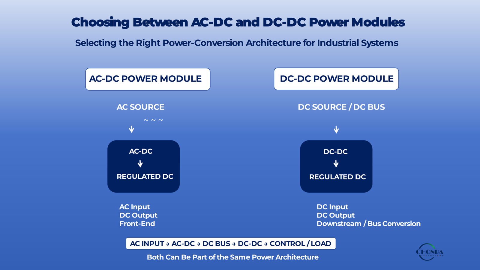
Choosing Between AC-DC and DC-DC Power Modules
Introduction: AC-DC or DC-DC — Where Should the Power Conversion Start?
Choosing between an AC-DC power module and a DC-DC power module should begin with one basic question:
What is the available power source?
If the system is supplied directly from an AC source, such as an industrial mains supply, an AC-DC power module may be the natural starting point for converting the available AC power into regulated DC power.
If the system already has a DC source, such as a battery, photovoltaic bus, energy-storage DC bus, or an existing industrial DC rail, a DC-DC power module may be more appropriate for converting one DC voltage into another.
The distinction is simple at the input level, but the final selection depends on much more than AC or DC.
Engineers may also need to consider:
- Input-voltage range
- Required output voltage and current
- Power rating
- Galvanic isolation
- Voltage regulation
- Power factor correction where applicable
- Efficiency
- EMI and electrical noise
- Thermal conditions
- Protection functions
- Mechanical and integration requirements
In many industrial systems, AC-DC and DC-DC power modules are not competing alternatives at all. They may be used together within the same power architecture.
For example:
AC Input → AC-DC Power Module → DC Bus → DC-DC Power Module → Regulated Load
Understanding where the power-conversion process begins, where voltage conversion is required, and whether isolation or regulation is needed at each stage is essential for selecting the right power-module architecture.
This guide compares AC-DC and DC-DC power modules from an engineering perspective and provides a practical framework for deciding which solution is better suited to a specific application.
1. What Is an AC-DC Power Module?
An AC-DC power module is a power-conversion component that converts an AC input into a regulated DC output for electronic or industrial equipment.
It is often used as the front-end power stage when the available electrical source is an AC supply but the downstream system requires DC power.
A typical AC-DC power-conversion process can be represented as:
AC Input → Rectification → Power Conversion → Regulation → DC Output
Depending on the architecture and application requirements, an AC-DC power module may also incorporate functions such as isolation, power-factor correction, filtering, and protection.
1.1 Typical Functions of an AC-DC Power Module
An AC-DC module may perform several functions within the overall power architecture.
AC input conversion
The module accepts AC power from a mains or industrial AC source and converts it into a form suitable for downstream DC power conversion.
DC voltage regulation
The output stage can provide a defined and regulated DC voltage for control electronics, embedded systems, sensors, communication equipment, and other loads.
Galvanic isolation where required
Some AC-DC architectures include electrical isolation between the AC input and DC output. Whether isolation is required depends on the equipment architecture, safety requirements, and application.
Power-factor correction where applicable
For some AC-powered equipment, power-factor correction may be required or beneficial. The need for PFC depends on the input power level, equipment requirements, applicable regulations, and the selected architecture.
Protection and filtering
Depending on the product design, an AC-DC module may also incorporate functions such as over-current protection, over-voltage protection, thermal protection, input filtering, and other power-management features.
1.2 Where AC-DC Power Modules Fit in a System
An AC-DC module often acts as the first major conversion stage in an AC-powered system.
For example:
AC Input → AC-DC Power Module → DC Bus → DC-DC Converter → Final Load
In this architecture, the AC-DC stage establishes the main DC power domain, while downstream DC-DC converters can generate additional voltage rails or provide isolated or application-specific power conversion.
This layered approach is common when different parts of an industrial system require different DC voltage levels.
1.3 Typical Applications
AC-DC power modules may be used in:
- Industrial automation equipment
- Control systems
- Embedded industrial electronics
- Measurement and monitoring equipment
- Communication equipment
- Industrial instruments
- Other AC-powered systems requiring regulated DC power
The appropriate AC-DC module depends on the input-voltage range, required output, power level, isolation requirements, thermal conditions, mechanical constraints, and system architecture.
An AC-DC power module is therefore not simply a component that converts AC to DC. It can form the front-end power stage of a larger power architecture and determine how subsequent DC power-conversion stages are supplied.
2. What Is a DC-DC Power Module?
A DC-DC power module is a power-conversion component that converts one DC voltage into another DC voltage for electronic or industrial equipment.
Unlike an AC-DC power module, a DC-DC module starts with an existing DC power source. It can therefore be used as a downstream conversion stage after an AC-DC front end, or as a direct power-conversion stage in systems that already operate from a DC bus.
A typical DC-DC power-conversion process can be represented as:
DC Input → DC-DC Conversion → Regulated DC Output
Depending on the topology and application, a DC-DC power module may be designed as either non-isolated or isolated.
2.1 Typical Functions of a DC-DC Power Module
A DC-DC module can perform several functions within a larger power architecture.
DC voltage conversion
The module can convert an available DC voltage into the level required by the downstream electronics.
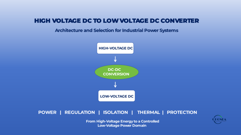
For example, a high-voltage DC bus may need to be converted to a lower-voltage auxiliary supply for monitoring, control, communication, or embedded electronics.
Voltage regulation
A regulated DC-DC module can maintain a stable output voltage despite defined variations in input voltage or load conditions.
The required regulation performance depends on the downstream equipment and application requirements.
Galvanic isolation where required
Some DC-DC modules provide electrical isolation between the input and output sides.
Isolated DC-DC architectures can be useful when different parts of a system must operate at different electrical potentials or when an isolated auxiliary power domain is required.
Wide input-voltage operation
Some DC-DC modules are designed to operate across a defined input-voltage range rather than from one fixed DC voltage.
This can be useful in systems where the available DC source varies during normal operation.
Protection and filtering
Depending on the design, a DC-DC module may include functions such as:
- Over-voltage protection
- Over-current protection
- Short-circuit protection
- Thermal protection
- Input and output filtering
The actual protection functions depend on the product architecture and application requirements.
2.2 Where DC-DC Power Modules Fit in a System
A DC-DC module can appear at different points within a power architecture.
For example:
Battery / PV / DC Bus → DC-DC Power Module → Regulated Load
or:
AC Input → AC-DC Power Module → DC Bus → DC-DC Power Module → Final Load
In the second architecture, the AC-DC stage establishes the main DC bus, while one or more DC-DC modules provide the voltage levels or isolated power domains required by individual parts of the equipment.
This modular approach can simplify the distribution of power across complex industrial systems.
2.3 Typical Applications
DC-DC power modules are commonly considered for:
- PV monitoring systems
- Solar combiner box monitoring
- Battery energy storage systems
- Industrial automation
- Robotics and embedded systems
- Industrial control electronics
- Communication equipment
- Isolated measurement systems
- Other DC-powered equipment
The appropriate DC-DC module depends on the input-voltage range, output requirements, power level, isolation requirements, efficiency, thermal conditions, and mechanical constraints.
A DC-DC power module is therefore not simply a device for changing one voltage into another. It can serve as a downstream, bus-level, or isolated power-conversion stage within a larger electrical architecture.
3. The Fundamental Difference: AC Source vs DC Source
The most fundamental difference between an AC-DC power module and a DC-DC power module is the type of electrical source available at the input.
An AC-DC power module starts with an AC source and creates a DC power domain for the downstream system.
A DC-DC power module starts with an existing DC source and converts that DC voltage into another DC voltage or power domain.
This distinction often determines where the module sits within the overall power architecture.
3.1 AC-DC: Converting the AC Source into a DC Power Domain
An AC-DC power module is commonly used as the front-end conversion stage when the available source is AC.
A simplified architecture is:
AC Source → AC-DC Power Module → DC Bus / Regulated DC Output
The AC-DC stage may include rectification, switching conversion, regulation, filtering, isolation where required, and power-factor correction where applicable.
It can therefore establish the main DC power domain from which other circuits or downstream converters are supplied.
3.2 DC-DC: Converting an Existing DC Power Domain
A DC-DC power module starts with a DC source that already exists within the system.
A simplified architecture is:
DC Source → DC-DC Power Module → Regulated DC Output
The DC source may come from:
- A battery
- A photovoltaic DC bus
- A BESS DC bus
- An industrial DC supply
- An existing DC rail created by an AC-DC front end
A DC-DC module may then generate the voltage required by a particular load, provide isolation between DC domains, or create additional power rails.
3.3 AC-DC and DC-DC Can Work Together
It is important to recognize that AC-DC and DC-DC power modules are not always competing alternatives.
A complex industrial system may use both:
AC Input → AC-DC Power Module → DC Bus → DC-DC Power Module → Final Load
In this architecture, the AC-DC module establishes the main DC power domain, while the DC-DC stage provides additional voltage conversion or isolated power for specific subsystems.
This modular approach can be useful when different parts of the equipment have different voltage, isolation, or regulation requirements.
3.4 Fundamental Comparison
| Consideration | AC-DC Power Module | DC-DC Power Module |
|---|---|---|
| Input source | AC | DC |
| Typical output | Regulated DC | Regulated DC |
| Typical system role | AC front-end | Downstream, bus-level, or isolated conversion |
| Rectification | Typically required | Not required in the same AC-input sense |
| PFC | May be required, depending on application | Generally not an AC-input power-factor issue |
| Isolation | May be isolated or non-isolated | May be isolated or non-isolated |
| Typical sources | Mains, industrial AC | Battery, PV bus, BESS bus, existing DC rail |
| Typical use | Establishing a DC power domain | Generating additional or different DC power domains |
| Typical architecture | AC → DC | DC → DC |
The table is a general architectural comparison. Actual implementations vary according to the selected topology, input and output requirements, power level, regulatory environment, and application.
3.5 Why the Input Source Matters
The input source determines the first major power-conversion problem the engineer needs to solve.
If the available source is AC, the design must address the requirements associated with AC input, such as rectification, input filtering, power factor where applicable, and any required isolation or safety functions.
If the available source is already DC, these AC-input functions are not part of the same conversion stage. The design can instead focus directly on DC voltage conversion, regulation, isolation where required, efficiency, thermal performance, and system integration.
This is why the correct question is not simply:
Which is better, AC-DC or DC-DC?
The more useful question is:
What power source does the system have, and where does the next required voltage conversion need to occur?
That question usually provides the correct starting point for selecting the power-module architecture.
4. When Should You Use an AC-DC Power Module?
An AC-DC power module is usually the appropriate starting point when the available power source is AC and the system requires a regulated DC power domain.
The key question is not whether AC-DC power conversion is generally better than DC-DC conversion, but whether the system needs to convert an existing AC source into the DC power required by the downstream electronics.
4.1 AC Is the Available Power Source
The most direct reason to use an AC-DC power module is that the available source is AC.
Typical sources may include:
- Industrial mains power
- AC distribution systems
- AC-powered equipment
- Other upstream AC sources
In these systems, an AC-DC module can provide the initial conversion stage needed to establish a DC power domain for the rest of the equipment.
4.2 The System Requires DC Output
Many industrial and electronic systems ultimately operate their control, sensing, communication, or embedded circuits from DC voltage.
If the available source is AC but the downstream electronics require a regulated DC supply, an AC-DC power module can perform the required front-end conversion.
For example:
AC Input → AC-DC Power Module → Regulated DC Output
The required output voltage and current depend on the downstream load and the overall system architecture.
4.3 A Complete AC Front-End Is Needed
An AC-powered system may require several functions before power reaches the downstream DC circuits.
Depending on the application, the AC-DC front end may need to address:
- Input rectification
- Input filtering
- Power conversion
- Output regulation
- Galvanic isolation where required
- Protection
- Power-factor correction where applicable
Integrating these functions into an AC-DC power module can simplify the development of the equipment’s primary power stage.
4.4 Power-Factor Requirements Matter
For some AC-powered equipment, power factor and input-current behavior are important design considerations.
Power-factor correction may be required or beneficial depending on factors such as:
- Input power level
- Equipment architecture
- Applicable regulations
- System power quality requirements
In such applications, the AC-DC stage may need to include an appropriate PFC architecture before the main DC conversion stage.
The exact requirement depends on the final equipment and applicable standards.
4.5 Isolation May Be Required
An AC-DC architecture may also need to provide electrical isolation between the input and output sides.
Whether isolation is required depends on:
- Safety requirements
- System architecture
- Working voltage
- Grounding strategy
- Downstream circuit requirements
An AC-DC power module can therefore serve not only as an AC-to-DC converter but also as the front-end isolation stage when the selected architecture provides the required isolation.
4.6 When AC-DC Is Usually the Natural Starting Point
An AC-DC power module is often a logical starting point when:
- The available source is AC.
- The main equipment requires DC power.
- A complete AC input stage is needed.
- PFC or other AC-input requirements must be addressed.
- Galvanic isolation is required.
- The system needs a defined DC bus for downstream circuits.
In these cases, the AC-DC module often becomes the first major power-conversion stage in the system.
A typical architecture may therefore look like:
AC Source → AC-DC Power Module → DC Bus → Downstream Loads or DC-DC Modules
The next question is whether the available source is already DC and therefore whether a DC-DC power module would be a more appropriate starting point.
5. When Should You Use a DC-DC Power Module?
A DC-DC power module is usually the appropriate starting point when the available power source is already DC and the system requires another DC voltage or power domain.
Unlike an AC-DC module, a DC-DC module does not need to establish a DC power domain from an AC source. Instead, it works with an existing DC supply and adapts that power to meet the requirements of downstream circuits.
5.1 The Source Is Already DC
The simplest reason to use a DC-DC power module is that the available source is already DC.
Typical sources include:
- Batteries
- Photovoltaic DC buses
- Battery energy storage systems
- Industrial DC supplies
- Existing DC rails generated by an AC-DC front end
In these systems, introducing an additional AC-DC conversion stage would add unnecessary conversion steps. A DC-DC module can instead convert the existing DC source directly into the required power domain.
5.2 Another DC Voltage Is Required
A DC-DC module is useful when the available DC voltage does not match the voltage required by the downstream electronics.
For example:
High-Voltage DC Bus → DC-DC Power Module → 24VDC Control Supply
or:
24VDC Source → DC-DC Power Module → 12VDC / 5VDC Load
The required conversion ratio, output current, regulation, and power level depend on the specific application.
For a more detailed introduction to high-voltage DC-DC converters, see What Is a High Voltage DC-DC Converter?.
5.3 A Wide DC Input Range Must Be Supported
Some industrial DC sources vary significantly during normal operation.
For example, battery systems, PV-related DC buses, and other power systems may operate across a defined voltage range rather than at one fixed voltage.
A DC-DC module can be designed to accept a specified input range while providing the required output voltage.
When evaluating such a module, engineers should consider:
- Minimum input voltage
- Maximum input voltage
- Nominal input voltage
- Input transients
- Required output regulation
For detailed selection considerations, see How to Select a High Voltage DC-DC Converter Module for Industrial Applications and DC-DC Converter Selection Guide: Key Parameters for High Voltage Applications.
5.4 Isolation Is Required Between DC Domains
A DC-DC converter may also be used when two DC power domains need to be electrically isolated.
An isolated DC-DC architecture can provide:
- Galvanic isolation
- DC voltage conversion
- Output regulation
- A separate power domain for sensitive electronics
This can be useful in applications such as:
- PV monitoring
- Industrial measurement
- Communication systems
- Battery systems
- Control electronics
The required isolation level, creepage, clearance, and insulation system should be evaluated according to the operating conditions and applicable requirements.
5.5 A Compact Downstream Power Stage Is Needed
DC-DC conversion is often used as a downstream stage because different parts of an industrial system may require different voltage levels.
For example:
AC Input → AC-DC Power Module → DC Bus
followed by:
DC Bus → DC-DC Power Module → Control / Monitoring Electronics
This modular architecture allows different parts of the equipment to use the voltage levels they actually require without redesigning the entire front-end power stage.
Compact DC-DC modules can be particularly useful when PCB area, equipment size, weight, or power density is important.
5.6 When DC-DC Is Usually the Natural Starting Point
A DC-DC power module is often the logical starting point when:
- The available power source is already DC.
- A different DC voltage is required.
- The input voltage varies over a defined range.
- Electrical isolation is required between DC domains.
- A compact downstream power stage is needed.
- The system already contains an upstream AC-DC or other DC power source.
A typical architecture may therefore be:
DC Source → DC-DC Power Module → Regulated Load
or:
AC Source → AC-DC Power Module → DC Bus → DC-DC Power Module → Final Load
The key question is whether the system already has a suitable DC power domain from which the next stage of conversion can begin.
6. AC-DC and DC-DC Are Often Used Together
AC-DC and DC-DC power modules are not always competing alternatives.
In many industrial and electronic systems, they work together as different stages within the same power architecture.
A typical architecture may look like:
AC Input → AC-DC Power Module → DC Bus → DC-DC Power Module → Point-of-Load / Control / Monitoring
In this configuration, the AC-DC module establishes the main DC power domain, while one or more DC-DC modules generate the specific voltage rails required by individual parts of the system.
6.1 The AC-DC Module as the Front-End Stage
The AC-DC module is commonly used to convert the available AC source into a suitable DC bus.
Depending on the application, this stage may provide:
- AC rectification
- Power conversion
- Voltage regulation
- Isolation where required
- Power-factor correction where applicable
- Input and output filtering
- Protection functions
The resulting DC bus can then supply multiple downstream circuits.
6.2 DC-DC Modules as Downstream Conversion Stages
Once a suitable DC bus has been established, DC-DC modules can generate additional voltage rails for specific loads.
For example, one system may use:
AC Input → AC-DC → 48VDC Bus
and then:
48VDC → DC-DC → 24VDC Control
48VDC → DC-DC → 12VDC Communication
48VDC → Isolated DC-DC → Monitoring Circuit
This approach allows different parts of the equipment to receive the voltage and isolation characteristics they actually require.
6.3 Why Use Multiple Conversion Stages?
Using more than one power-conversion stage can provide several architectural advantages.
Different subsystems may have different requirements for:
- Voltage
- Current
- Isolation
- Regulation
- Noise performance
- Power density
- Protection
Rather than forcing one power module to satisfy every load, the system can distribute these functions across different conversion stages.
This can simplify the design of individual power domains and make the overall architecture easier to adapt to different loads.
6.4 When a Combined Architecture Makes Sense
A combined AC-DC and DC-DC architecture may be useful when:
- The primary source is AC.
- The equipment contains multiple DC voltage domains.
- Some loads require isolated power.
- Different subsystems require different voltage levels.
- A central DC bus can simplify power distribution.
- Downstream circuits have different regulation or power requirements.
The exact architecture depends on the power level, voltage range, isolation requirements, efficiency targets, thermal conditions, and system layout.
6.5 Avoiding Unnecessary Conversion Stages
Although multiple conversion stages can provide flexibility, adding unnecessary stages can also increase:
- Power losses
- Component count
- Cost
- Thermal load
- EMI sources
- System complexity
The goal is therefore not to use as many conversion stages as possible.
Instead, engineers should determine where each conversion function is actually required and choose the simplest architecture that satisfies the complete system requirements.
For a broader discussion of system-level power-supply architecture, see High Voltage Power Supply Design Guide.
The key idea is that AC-DC and DC-DC modules often work as complementary building blocks within the same power system rather than as mutually exclusive choices.
7. Key Selection Factors
Once the basic power architecture has been identified, engineers can compare AC-DC and DC-DC power modules using a concise set of selection factors.
No single specification determines whether a module is suitable. The final choice should be based on how the electrical, thermal, EMI, isolation, and mechanical requirements work together.
| Selection Factor | What to Check |
|---|---|
| Input Source | Confirm whether the available source is AC or DC and determine where the power-conversion stage will sit in the system. |
| Input Range | Check the minimum, nominal, and maximum operating voltage as well as expected transients. |
| Output Voltage | Confirm the required output voltage and allowable regulation range for the downstream load. |
| Output Current | Evaluate continuous current, peak current, and the actual load profile. |
| Power | Select a suitable power range with appropriate operating margin rather than simply choosing the highest rating. |
| Isolation | Determine whether galvanic isolation is required and verify the required isolation performance. |
| Regulation | Consider line regulation, load regulation, ripple, and transient response according to the load requirements. |
| PFC | For AC-input systems, determine whether power-factor correction is required or beneficial for the application. |
| Efficiency | Compare efficiency across the actual expected load range rather than relying only on a peak-efficiency value. |
| EMI | Evaluate switching noise, common-mode and differential-mode noise, filtering, grounding, and system sensitivity. |
| Thermal | Consider losses, ambient temperature, cooling conditions, temperature rise, and derating. |
| Mechanical Size | Check PCB area, mounting, connector position, enclosure space, and overall mechanical integration. |
These factors should be considered together.
For example, a compact DC-DC module may appear attractive because of its power density, but it may not be suitable if the input range, isolation requirements, thermal conditions, or EMI performance do not match the application.
Similarly, an AC-DC module with the correct output voltage may still require additional downstream DC-DC conversion if different parts of the equipment operate at different voltage levels.
For a broader system-level design framework, see High Voltage Power Supply Design Guide.
For more detailed DC-DC selection parameters, see How to Select a High Voltage DC-DC Converter Module for Industrial Applications and DC-DC Converter Selection Guide: Key Parameters for High Voltage Applications.
Detailed EMI, thermal, and PCB considerations are covered in High Voltage DC-DC Converter EMI Design Considerations, High Voltage DC-DC Converter Thermal Management, and High Voltage DC-DC Converter PCB Design Considerations.
The final selection should always be based on the complete system requirements rather than on one specification in isolation.
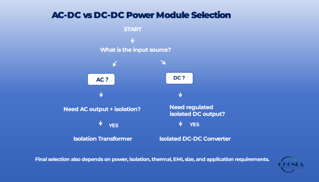
8. A Practical Decision Guide
Choosing between an AC-DC and a DC-DC power module can be simplified by starting with the available power source and then checking the main system requirements.
Step 1: What Is the Available Power Source?
AC → Consider an AC-DC Power Module
If the available source is AC and the downstream system requires DC power, an AC-DC module is usually the natural starting point.
DC → Consider a DC-DC Power Module
If the system already has a DC source or DC bus, a DC-DC module may be the more direct conversion stage.
Step 2: Is Galvanic Isolation Required?
If electrical isolation is required, determine whether the selected AC-DC or DC-DC architecture provides the required isolation performance.
Isolation requirements may include:
- Working voltage
- Isolation voltage
- Creepage
- Clearance
- Insulation system
The isolation requirement should be evaluated as part of the complete system rather than as a single module specification.
Step 3: Is a Regulated Output Required?
If the downstream electronics require a controlled DC voltage, verify the module’s regulation performance under the expected input and load conditions.
Important considerations may include:
- Output-voltage tolerance
- Line regulation
- Load regulation
- Transient response
- Output ripple
Step 4: Does the Input Voltage Vary Over a Wide Range?
If the source voltage changes significantly during normal operation, check whether the selected module supports the complete operating range.
This is particularly important for applications involving:
- PV DC buses
- Batteries
- BESS
- Variable industrial DC supplies
Step 5: Check the Complete Integration Requirements
Once the basic architecture has been selected, confirm that the module also meets:
Power → Efficiency → EMI → Thermal → Protection → Mechanical Integration
A module that passes the basic input and output requirements may still require additional evaluation before it can be integrated into the final equipment.
A Simple Architecture Guide
The decision process can be summarized as:
AC Source → AC-DC Power Module → DC Power Domain
DC Source → DC-DC Power Module → Required DC Power Domain
In more complex systems:
AC Source → AC-DC Power Module → DC Bus → DC-DC Power Module → Point-of-Load / Control / Monitoring
The purpose of this decision process is not to identify one universally better module, but to determine which power-conversion architecture best matches the available source and the requirements of the complete system.
9. Standard vs Custom Power Modules
Once the basic AC-DC or DC-DC architecture has been selected, engineers should determine whether a standard power module is sufficient or whether some level of customization is required.
A practical approach is to consider three levels of implementation.
9.1 Standard Module
A standard module is usually the best choice when the existing specifications already match the application.
It may be appropriate when:
- Input and output requirements are within the standard range.
- Power rating is suitable.
- Isolation requirements are already supported.
- Mechanical dimensions are acceptable.
- Development time is important.
A standard module can reduce development effort and help accelerate prototype testing and production.
9.2 Modified Standard
A modified standard solution can be considered when the basic power architecture is suitable but one or more parameters need to be adjusted.
Typical modifications may include:
- Input-voltage range
- Output voltage or current
- Mechanical dimensions
- Connector configuration
- Protection functions
- Thermal requirements
This approach can provide a practical balance between development speed and application-specific requirements.
9.3 Custom Module
A fully customized power module may be appropriate when the application has requirements that fall substantially outside the available standard product range.
Examples include:
- Unusual input-voltage ranges
- Special output requirements
- Non-standard isolation
- Restricted mechanical space
- Application-specific thermal requirements
- Special EMI or protection requirements
A custom solution can be designed around the actual system constraints rather than requiring the equipment design to adapt to an unsuitable standard module.
Choosing the Right Level of Customization
The goal is not to customize every project.
A useful decision sequence is:
Standard → Modified Standard → Custom
Start with an existing module whenever it meets the application requirements. Move to a modified standard solution when only limited changes are needed, and consider a fully custom design when the electrical, mechanical, isolation, thermal, or application requirements cannot be addressed effectively by an existing platform.
For a broader discussion of standard versus custom high-voltage power-supply solutions, see Standard vs Custom High-Voltage Power Supply Design.
10. Application Examples
The most suitable power-module architecture often becomes clearer when the application and its available power source are considered together.
AC-DC and DC-DC modules may serve very different roles depending on how power enters the system and where voltage conversion is required.
| Application | Likely Architecture | Why |
|---|---|---|
| AC-powered industrial equipment | AC-DC | The primary source is AC and the equipment requires a regulated DC power domain. |
| PV monitoring systems | DC-DC | The system can draw power from an existing high-voltage DC bus and convert it to a lower regulated DC supply for monitoring electronics. |
| BESS monitoring | DC-DC | Battery and storage systems already provide a DC source, making DC-DC conversion a natural downstream stage. |
| Robotics with battery/DC bus | DC-DC | The robot already has a DC power source and may require multiple regulated voltage rails for control and embedded electronics. |
| Industrial controller supplied from mains | AC-DC | AC mains power must first be converted into a suitable DC supply for the controller and connected electronics. |
| Complex industrial equipment | AC-DC + DC-DC | An AC-DC front end can establish the main DC bus, while downstream DC-DC modules generate additional voltage rails or isolated power domains. |
10.1 Why the Same Application Can Use Different Architectures
The examples above represent common architectural choices rather than fixed rules.
A single application may use different power-module architectures depending on how the equipment is powered.
For example, an industrial automation system supplied directly from AC mains may begin with an AC-DC module.
The same system, if it already contains a DC bus generated elsewhere, may instead use one or more DC-DC modules.
Similarly, a robotics platform may use DC-DC conversion internally but still require an AC-DC stage in a charging or external power-supply subsystem.
10.2 Think in Terms of the Power Path
A useful way to evaluate an application is to follow the power path from the original source to the final load.
For example:
AC Source → AC-DC → DC Bus → DC-DC → Control / Monitoring
or:
Battery / PV DC Bus → DC-DC → Regulated Load
This approach helps engineers identify which conversion stage is actually required rather than selecting a module based only on the application name.
The correct power-module architecture ultimately depends on the source, voltage-conversion requirements, isolation, regulation, power level, and system integration constraints.
11. Common Selection Mistakes
Choosing between AC-DC and DC-DC power modules can appear straightforward, but several common mistakes can lead to unnecessary complexity, poor performance, or an unsuitable power architecture.
The following checks can help engineers avoid some of the most common selection problems.
11.1 Choosing Based Only on Nominal Voltage
Selecting a module based only on the nominal input voltage can be risky.
For example, a system described as a “48V DC system” or “1000V DC system” may operate across a much wider range and may also experience startup or transient conditions.
The complete operating range should always be reviewed before selecting a module.
11.2 Ignoring the Actual Power Source
Another common mistake is focusing on the required output without first identifying where the power actually comes from.
If the source is already DC, adding an unnecessary AC-DC stage increases conversion steps without solving a real system requirement.
Likewise, if the equipment is supplied directly from AC, a DC-DC module alone cannot replace the required AC-to-DC front-end conversion.
11.3 Assuming AC-DC and DC-DC Are Interchangeable
AC-DC and DC-DC modules may both provide regulated DC output, but they solve different input-conversion problems.
AC-DC modules start from AC.
DC-DC modules start from an existing DC power domain.
Treating them as interchangeable can result in unnecessary stages or an incomplete power architecture.
11.4 Assuming Isolation Is Always Required
Some applications require galvanic isolation, while others do not.
Isolation should be determined from:
- System architecture
- Working voltage
- Grounding requirements
- Safety requirements
- Downstream circuit requirements
Adding an isolated module when isolation is unnecessary may increase cost, size, and complexity.
At the same time, omitting required isolation can create significant safety and system-integration problems.
11.5 Looking Only at Peak Efficiency
A module with a higher peak-efficiency value is not automatically the better choice.
Engineers should consider efficiency across the actual expected operating range, including:
- Light load
- Typical load
- Full load
- Startup and transient conditions
Thermal performance and power loss should be evaluated together with efficiency.
11.6 Ignoring Downstream Conversion Stages
Choosing a power module only for the immediate load can overlook the requirements of other parts of the system.
For example, an AC-DC module may provide a suitable main DC bus, but downstream DC-DC conversion may still be required for:
- Control electronics
- Communication circuits
- Monitoring systems
- Sensors
- Isolated power domains
The complete power path should therefore be considered rather than selecting each module independently.
11.7 Ignoring Mechanical and Thermal Integration
A module that meets the electrical specifications may still be unsuitable if it does not fit the enclosure, PCB, or cooling system.
Before final selection, engineers should also verify:
- PCB dimensions
- Mounting
- Connector position
- Cooling
- Ambient temperature
- Airflow
- Installation constraints
11.8 Selecting More Power Than the System Actually Needs
Choosing the highest available power rating can increase cost and size without providing useful benefits.
The appropriate power rating should be based on the actual load profile and a reasonable design margin.
The goal is to provide sufficient capacity without unnecessarily oversizing the power-conversion stage.
11.9 Treating the Module as a Standalone Component
A power module does not operate independently from the rest of the system.
Its performance can be affected by:
- Input source characteristics
- Wiring
- PCB layout
- Grounding
- Cooling
- Load behavior
- Mechanical integration
The module should therefore be selected as part of the complete power architecture.
11.10 A Better Selection Principle
A reliable selection process starts with:
Source → Input Range → Output → Power → Isolation → Regulation → Efficiency → EMI → Thermal → Integration
The goal is not to select the most powerful, smallest, or highest-efficiency module available.
The goal is to select the module architecture that satisfies the complete system requirements with appropriate performance margin and reasonable complexity.
For a broader system-level design framework, see High Voltage Power Supply Design Guide.
For detailed DC-DC selection considerations, see How to Select a High Voltage DC-DC Converter Module for Industrial Applications and DC-DC Converter Selection Guide: Key Parameters for High Voltage Applications.
Conclusion
Choosing between an AC-DC and a DC-DC power module should begin with the available power source and the role of the power-conversion stage within the complete system.
An AC-DC power module is typically the natural starting point when the available source is AC and the equipment requires a regulated DC power domain.
A DC-DC power module is generally more appropriate when a suitable DC source or DC bus already exists and another DC voltage, regulated output, or isolated DC power domain is required.
In many industrial systems, the two architectures are not alternatives at all. An AC-DC module may establish the main DC bus, while downstream DC-DC modules provide additional voltage rails, isolated power, or point-of-load conversion for individual subsystems.
The final selection should therefore consider the complete requirements, including:
Input → Input Range → Output → Power → Isolation → Regulation → PFC → Efficiency → EMI → Thermal → Mechanical Integration
The right power module is not necessarily the smallest, most powerful, or highest-efficiency option. It is the solution that best matches the electrical architecture, operating conditions, downstream load requirements, and long-term system objectives.
For engineers developing industrial automation, PV monitoring, BESS, robotics, embedded electronics, or other power-intensive systems, understanding where AC-DC and DC-DC modules fit within the overall power architecture can help reduce unnecessary conversion stages and simplify system integration.
CHONDA supports both AC-DC and DC-DC power modules, together with transformer and customized power solutions for application-specific industrial power requirements.
Related Articles
High Voltage Power Supply Design Guide
Explore a system-level framework for high-voltage power-supply architecture, isolation, regulation, EMI, thermal management, protection, PCB design, and power-module selection.
What Is a High Voltage DC-DC Converter?
Understand the basic principles, architecture, and applications of high-voltage DC-DC converters for industrial power systems.
How to Select a High Voltage DC-DC Converter Module for Industrial Applications
Learn which electrical, isolation, thermal, and application parameters should be evaluated when selecting a high-voltage DC-DC module.
DC-DC Converter Selection Guide: Key Parameters for High Voltage Applications
Review the major selection parameters for high-voltage DC-DC converters, including input range, output requirements, power, isolation, and operating conditions.
Isolation Transformer vs Isolated DC-DC Converter: Which Is Right for Your Application?
Compare transformer-based and isolated DC-DC architectures in terms of isolation, regulation, efficiency, EMI, power density, and application requirements.
High Voltage DC-DC Converter PCB Design Considerations
Explore how creepage, clearance, PCB layout, switching loops, grounding, and return paths affect high-voltage DC-DC converter performance.