We help the world since 2012

Wide Input DC-DC Converter Design Guide
A DC-DC converter does not always operate from a perfectly stable DC source. In real-world systems, the input voltage may vary because of battery discharge, power distribution changes, load transients, startup conditions, regeneration, or other disturbances.
A wide input DC-DC converter is designed to maintain stable and reliable output power across a defined range of input voltages rather than operating around a single nominal input value.
This makes wide input converters particularly useful in railway systems, industrial automation, battery-powered equipment, telecommunications, renewable energy systems, and other applications where the available DC bus voltage can vary significantly.
However, a wider input range does not automatically mean a better converter. As the input range increases, engineers must consider efficiency, thermal performance, control-loop behavior, input protection, EMI, isolation, and output regulation across the entire operating range.
This guide explains how wide input DC-DC converters work, why wide input capability matters, how to select the appropriate input range, and which engineering trade-offs should be evaluated before choosing a converter.
1. What Is a Wide Input DC-DC Converter?
A wide input DC-DC converter is a converter designed to operate normally across a relatively broad specified input-voltage range while maintaining its required output performance.
In practical power systems, the input voltage supplied to a DC-DC converter is not always fixed. Battery voltage changes with the state of charge, vehicle and railway power systems can experience voltage fluctuations, and industrial equipment may operate across different nominal bus voltages.
For this reason, engineers often evaluate a converter by its input voltage range rather than by a single nominal voltage.
1.1. What Does Wide Input Mean?
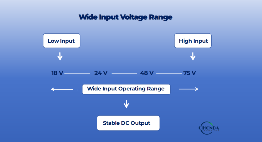
The input voltage range defines the DC voltage that a converter is designed to accept during normal operation.
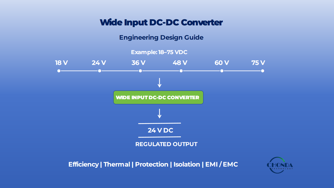
For example, a converter specified as:
Input: 18–75 VDC
has:
- Minimum input voltage: 18 VDC
- Maximum input voltage: 75 VDC
- Nominal applications: may include 24 V and 48 V DC systems
- Specified operating range: 18–75 VDC
This does not mean that the converter is automatically suitable for every 24 V or 48 V system. The actual application must also be evaluated against factors such as transient voltage, output power, protection requirements, thermal conditions, efficiency, EMC performance, and the converter’s actual operating specifications.
1.2. Key Input-Voltage Terms Engineers Should Understand
When selecting a wide input DC-DC converter, several voltage terms are important.
Nominal input voltage refers to the normal or representative voltage of the system, such as a 24 V or 48 V DC bus.
Minimum operating voltage is the lowest input voltage at which the converter is specified to maintain normal operation and required output performance.
Maximum operating voltage is the highest input voltage within the specified continuous operating range.
Input voltage ratio describes how broad the input range is relative to the lower end of the range. For example, an 18–75 VDC input range spans more than four times the minimum input voltage.
Continuous operating range refers to the voltage range within which the converter can operate continuously under its specified conditions.
Transient voltage range is different. A system may experience short-duration voltage changes caused by switching, load changes, battery conditions, motor operation, railway power disturbances, or other system events. A converter’s ability to tolerate these conditions depends on its specified input limits, protection design, and application requirements.
Therefore, engineers should not select a converter based only on the nominal bus voltage.
1.3. Example: 18–75 VDC Wide Input
Consider a DC-DC converter with an input specification of 18–75 VDC.
The converter may be used in systems built around common 24 V or 48 V nominal buses, because both nominal voltages fall within the specified input range.
However, the actual system voltage may vary around its nominal value.
For a 24 V system, the engineer should verify:
- the minimum actual bus voltage;
- the maximum continuous bus voltage;
- startup and shutdown conditions;
- transient voltage conditions;
- required output power;
- protection requirements; and
- thermal and EMC conditions.
The same principle applies to a 48 V system.
A wide input converter therefore provides input-voltage flexibility, but it does not remove the need for application-specific engineering validation.
1.4. Why Wide Input Capability Matters
A wider input range can simplify power-system design by allowing one converter design to support multiple nominal bus voltages or a wider range of real-world operating conditions.
This can be particularly valuable in applications such as:
- railway auxiliary power;
- industrial automation;
- battery-powered equipment;
- telecommunications;
- energy storage systems;
- vehicle electronics; and
- other variable-voltage DC bus applications.
However, a wider input range should always be evaluated together with output regulation, efficiency, thermal performance, protection, isolation, EMC, and transient capability.
The practical question is therefore not simply:
“How wide is the input range?”
but:
“Does the specified input range cover the complete voltage profile of my actual system?”
That distinction is important when selecting a reliable wide input DC-DC converter.
2. Wide Input vs Fixed Input DC-DC Converter
When selecting a DC-DC converter, one of the first decisions engineers need to make is whether the application requires a fixed-input converter or a wide-input converter.
The difference is not simply the number of voltage values listed on a datasheet. It affects the converter’s operating window, protection requirements, control design, thermal behavior, and overall system flexibility.
| Feature | Fixed Input | Wide Input |
|---|---|---|
| Input voltage | Narrow specified range | Broad specified range |
| Source variation | Limited | Higher |
| System flexibility | Lower | Higher |
| Application range | More specific | More versatile |
| Protection requirement | Simpler | More demanding |
| Thermal design | More predictable | Must cover wider operating conditions |
| Control design | Narrow operating window | Wider operating window |
2.1. Fixed Input DC-DC Converter
A fixed-input converter is designed around a relatively narrow and well-defined input-voltage condition.
For example, a converter may be optimized for a specific nominal supply such as 24 VDC, with only a limited amount of variation around that operating point.
This approach can simplify several aspects of the design because the converter operates within a more predictable electrical environment.
The narrower input range may allow engineers to optimize:
- switching and control parameters
- power-stage components
- protection thresholds
- thermal performance
- efficiency
- magnetic component design
Fixed-input converters can therefore be appropriate when the power source is stable and well controlled and the application does not require significant input-voltage variation.
2.2. Wide Input DC-DC Converter
A wide-input converter is designed to maintain normal operation across a substantially broader specified input-voltage range.
For example, an 18–75 VDC converter may accommodate systems commonly associated with both 24 V and 48 V nominal power architectures.
The wider operating range provides greater flexibility when the input voltage can vary because of:
- battery charge and discharge
- load variation
- cable voltage drop
- startup conditions
- braking or regenerative events
- variations in distributed power systems
However, the wider range also places greater demands on the converter’s electrical and thermal design.
The power stage, switching devices, control loop, protection thresholds, magnetic components, filtering, and thermal management may all need to remain effective across the complete specified input range.
2.3. Which One Should Engineers Choose?
The choice depends on the characteristics of the actual power system.
A fixed-input converter may be preferable when the input voltage is stable, predictable, and tightly controlled.
A wide-input converter becomes more attractive when the input source can vary significantly during normal operation or when one converter needs to support multiple nominal voltage conditions.
The important point is that a wider input range should not be selected simply because it appears more versatile on a datasheet.
Engineers should evaluate the complete system requirements, including:
- minimum and maximum continuous input voltage
- transient voltage conditions
- required output power
- efficiency across the input range
- thermal environment
- protection requirements
- isolation requirements
- EMC performance
- expected operating lifetime
A wide-input converter provides greater system flexibility, but the wider operating range also increases the engineering requirements placed on the converter.
3. Why Do Systems Need Wide Input Voltage?
A DC power source is rarely as stable as a single nominal voltage printed on a system specification.
In real-world applications, the input voltage of a DC-DC converter may change because of battery state, load conditions, cable losses, power-system disturbances, startup events, or variations in the upstream power network.
This is why engineers may specify a wide input voltage range rather than designing the converter around one fixed nominal voltage.
The key requirement is not simply that the converter accepts several voltage values. The converter must maintain stable and predictable operation across the specified continuous input range, while also handling applicable transient and protection conditions defined by the system.
3.1. Battery Voltage Variation
Battery-powered systems are one of the most common reasons for requiring a wide-input DC-DC converter.
A battery does not remain at its nominal voltage throughout its operating cycle. Its voltage can change with:
- state of charge
- charging conditions
- discharge conditions
- load current
- battery chemistry
- temperature
- cable and connection losses
For example, a system described as a 24 V battery system does not necessarily provide exactly 24 V to the converter at all times.
The converter may need to operate at a lower voltage during discharge and at a higher voltage during charging or other operating conditions.
A wide-input converter can therefore provide a larger operating window without requiring a separate converter for every possible battery voltage condition.
However, the actual minimum and maximum input voltages must always be defined from the battery system and application requirements rather than assumed from the nominal battery voltage.
3.2. Railway Power Systems
Railway applications are another important example of why input-voltage flexibility matters.
Railway electrical systems can involve different nominal supply architectures, and the voltage experienced by onboard equipment may vary under normal operating conditions as well as during abnormal or transient events.
For rolling-stock electronic equipment, EN 50155 defines requirements for electronic equipment used in railway vehicles, including requirements that must be considered when evaluating the equipment’s supply conditions. Railway traction-system supply characteristics are separately addressed by IEC 60850.
Therefore, railway converter selection should not be based only on the nominal voltage printed on the system specification.
Engineers typically need to evaluate:
- nominal input voltage
- continuous operating range
- minimum and maximum operating voltage
- voltage dips and interruptions where applicable
- transient overvoltage conditions
- required output power
- protection thresholds
- thermal operating conditions
This is where a properly specified wide-input DC-DC converter can provide valuable design flexibility.
Related application guide:
→ Railway DC-DC Converter
3.3. Industrial Automation
Industrial automation systems can experience significant variation in their DC power environment.
Controllers, sensors, PLCs, industrial computers, communication modules, and other embedded electronics may share a common DC distribution network.
Voltage variation can result from:
- long cable runs
- changing machine loads
- distributed power supplies
- startup conditions
- motor-related disturbances
- local voltage drops
A wide-input converter can help maintain a stable secondary voltage while the upstream DC supply changes within the specified operating range.
This can be particularly useful when the same converter platform needs to support different machine configurations or supply architectures.
3.4. Telecommunication
Telecommunication equipment often operates from established DC power architectures, but the voltage available to individual electronic modules can still vary with battery operation, backup-power conditions, distribution losses, and system loading.
A wide-input DC-DC converter can allow one power-conversion stage to accommodate a broader range of supply conditions while providing a regulated output for sensitive communication electronics.
This can simplify system-level power architecture when the input source is not tightly regulated.
3.5. Renewable Energy
Renewable-energy systems introduce another type of input-voltage variation.
The available DC voltage may change with:
- operating conditions
- source voltage
- load
- power-conversion stage
- environmental conditions
- system configuration
A converter designed for a wider input range can provide greater tolerance to these variations, provided that the specified voltage range, power level, isolation, protection, and transient requirements match the actual application.
For renewable-energy equipment, wide input capability should therefore be evaluated together with the complete power architecture rather than treated as an isolated converter feature.
3.6. Battery Energy Storage
Battery energy storage systems (BESS) can have a particularly broad operating voltage window.
The battery voltage changes as the battery charges and discharges, while the system may also experience changes caused by:
- battery configuration
- state of charge
- charging and discharging power
- protection events
- contactor operation
- DC bus conditions
A DC-DC converter used inside or around a BESS therefore needs to be evaluated against the actual battery voltage envelope, not simply the nominal battery voltage.
This is one reason wide-input power conversion can be valuable in battery-based energy systems.
Related application guide:
→ Battery Energy Storage (BESS)
3.7. PV Monitoring
PV monitoring systems provide another clear example.
The DC voltage available from a photovoltaic string can vary with operating conditions, system configuration, and environmental conditions.
A monitoring power supply therefore needs to remain functional across the voltage range expected by the actual PV string or monitoring architecture.
A wide-input DC-DC converter can help provide a stable auxiliary supply while accommodating changes in the upstream DC voltage.
However, engineers still need to verify the actual minimum and maximum operating voltage, transient conditions, required isolation, power level, and protection requirements.
Related application guide:
→ PV Monitoring Power Supply
3.8. Wide Input Is a System Requirement, Not Just a Converter Feature
Across battery systems, railway equipment, industrial automation, telecommunications, renewable energy, BESS, and PV monitoring, the underlying engineering problem is similar:
the input voltage is not necessarily constant.
A wide-input DC-DC converter can provide a larger operating window, but the correct range must be determined from the real system conditions.
Engineers should therefore define:
Nominal Voltage → Continuous Operating Range → Minimum/Maximum Voltage → Transient Conditions → Converter Specification
A converter should be selected only after the complete voltage envelope and application requirements have been established.
4. How Wide Input DC-DC Converters Maintain Stable Output
A wide-input DC-DC converter is designed to accept changes in input voltage while maintaining a controlled and usable output voltage.
The key principle is simple:
As input voltage changes, the converter’s control system adjusts its operating conditions to maintain the required output voltage.
The exact mechanism depends on the converter topology, control architecture, transformer structure, switching devices, and operating mode. However, most regulated wide-input converters rely on coordinated control of several electrical parameters.
4.1. Input Voltage Changes
When the input voltage changes, the relationship between the converter’s input power stage and regulated output also changes.
For example, a converter specified for 18–75 VDC input and 24 VDC output must maintain the required output across a substantially wider input range than a converter designed for a narrow input window.
At lower input voltage, the converter may need to transfer more energy per switching cycle or operate with a different control condition to maintain the output.
At higher input voltage, the converter must prevent excessive energy transfer while maintaining regulation and keeping component stresses within their specified limits.
The converter therefore needs to remain stable at both ends of the specified operating range.
4.2. Regulation
Voltage regulation is the process of maintaining the output voltage within its specified limits despite changes in input voltage, load, temperature, and other operating conditions.
For a regulated converter, the nominal output is not simply determined by the input voltage.
Instead, the power stage and control system continuously work together to maintain the target output.
This is particularly important for systems that supply sensors, controllers, communication circuits, or other electronics that require a relatively stable DC voltage.
4.3. Duty Cycle
In many switching converters, the controller can adjust the duty cycle of the switching waveform to influence how energy is transferred through the power stage.
When input voltage changes, the required duty cycle may also change.
At a lower input voltage, the controller may increase the effective energy transfer per switching cycle. At a higher input voltage, it may reduce the corresponding control demand.
The exact relationship depends strongly on the converter topology and operating mode, so duty-cycle behavior should not be treated as a universal formula for every DC-DC converter.
The important engineering principle is that the control system has a mechanism for adapting power-stage operation as the input condition changes.
4.4. Switching Frequency
Switching frequency is another design parameter that can influence converter behavior.
Depending on the topology and control strategy, a converter may use a fixed switching frequency, variable frequency, pulse-width modulation, or other control techniques.
Switching frequency affects several aspects of the design, including:
- energy transfer per switching cycle
- magnetic component size
- switching losses
- EMI behavior
- control-loop dynamics
- thermal performance
For a wide-input converter, the selected switching strategy must remain effective across the complete specified input-voltage range.
Increasing switching frequency does not automatically make a converter better. Higher frequency can reduce magnetic-component size, but it can also increase switching losses and make EMI control more demanding.
4.5. Transformer Ratio
For isolated DC-DC converters, the transformer turns ratio is an important part of the voltage-conversion design.
The transformer helps establish the relationship between the primary-side switching waveform and the secondary-side voltage.
However, the transformer ratio alone does not determine whether a converter can support a wide input range.
The complete design also depends on the switching strategy, control range, power-stage components, magnetic design, rectification, regulation method, and protection limits.
A transformer ratio must therefore be selected together with the expected input-voltage range and output requirements.
4.6. Control Loop
The control loop is what allows a regulated converter to respond when operating conditions change.
A simplified control process can be understood as:
Output voltage → Feedback → Controller → Switching control → Power stage → Output voltage
If the output begins to move away from its target value, the feedback signal provides information to the controller. The controller then changes the relevant switching conditions to bring the output back toward its regulated value.
The implementation varies between converter architectures, but the underlying principle is the same: measure the output, compare it with the required operating condition, and adjust the power-conversion process.
4.7. Output Feedback
Output feedback provides the control system with information about the actual output condition.
This feedback can be used to compensate for changes caused by:
- input-voltage variation
- output-load variation
- component tolerances
- temperature changes
- power-stage losses
In an isolated converter, the feedback architecture may also need to transfer regulation information across the isolation boundary, depending on the design.
This is one reason why wide-input converter design involves more than simply specifying a broad input-voltage range.
4.8. The Core Engineering Principle
A wide-input converter must balance two requirements:
Accept a broad input range
and
Maintain a stable, predictable output
These requirements are achieved through the coordinated design of the power stage, switching control, magnetic components, feedback system, and protection functions.
The exact implementation varies with topology, but the fundamental principle remains:
As input voltage changes, the converter’s control system adjusts its operating conditions to maintain the required output voltage.
For example:
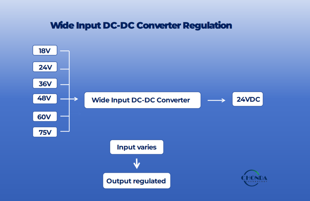
This means that the converter is not expected to produce a different output for each input voltage. Within its specified operating range, its regulation system works to maintain the required 24 V DC output.
5. Wide Input Range and Converter Efficiency
A wider input-voltage range can make a DC-DC converter more flexible, but it does not automatically make the converter more efficient.
Converter efficiency can vary with both input voltage and load condition. As the input voltage moves from the lower end to the upper end of the specified range, the converter may experience different current levels, switching conditions, conduction losses, and thermal behavior.
For this reason, engineers should evaluate efficiency across the actual operating range rather than relying only on a single peak-efficiency value.
5.1. Efficiency at Low Input Voltage
At a lower input voltage, a DC-DC converter generally needs to draw more input current to deliver the same output power.
For example, for a given output power, reducing the input voltage increases the required input current. Higher current can increase conduction losses in switches, inductors, transformers, PCB traces, connectors, and other power-path components.
As a result, efficiency may decrease toward the lower end of a wide input-voltage range, particularly when the converter is operating near its rated power.
The actual efficiency profile depends on the converter topology, switching devices, magnetic components, control strategy, and thermal design.
5.2. Efficiency at Nominal Input
Nominal input voltage often represents one of the most common operating conditions for the target application.
A converter may achieve its highest efficiency near a particular combination of input voltage and load because the power-stage components and control system are operating under favorable conditions.
However, nominal-input efficiency should not be treated as the overall efficiency of the converter.
For systems with variable input voltage, engineers should also examine how efficiency changes above and below the nominal operating point.
5.3. Efficiency at High Input Voltage
At higher input voltage, the input current required for a given output power is generally lower. This can reduce some conduction losses.
However, higher input voltage can also change switching conditions and other power-stage stresses. Depending on the converter topology and component selection, switching losses, voltage stress, electromagnetic interference, and thermal behavior may become more significant.
Therefore, a higher input voltage does not necessarily mean higher overall efficiency.
The converter must be designed so that its components and control system operate efficiently and reliably across the complete specified input range.
5.4. Why Efficiency Curves Matter
A converter’s efficiency should be evaluated as a function of both input voltage and load.
A device that reaches a very high peak efficiency at one operating point may perform differently when the input voltage changes or when the load moves away from that point.
For practical system design, engineers should consider:
- Efficiency at minimum input voltage
- Efficiency at nominal input voltage
- Efficiency at maximum input voltage
- Efficiency at light load
- Efficiency at typical operating load
- Efficiency near full load
- Thermal performance under representative conditions
A converter should not be evaluated only by its peak efficiency. Engineers should examine efficiency across the expected input-voltage and load range.
For wide-input DC-DC converters, this broader efficiency evaluation helps engineers determine whether the converter can maintain acceptable power loss, thermal performance, and system reliability under real operating conditions.
6. Thermal Challenges of Wide Input DC-DC Converters
Thermal performance is an important consideration when designing a wide-input DC-DC converter.
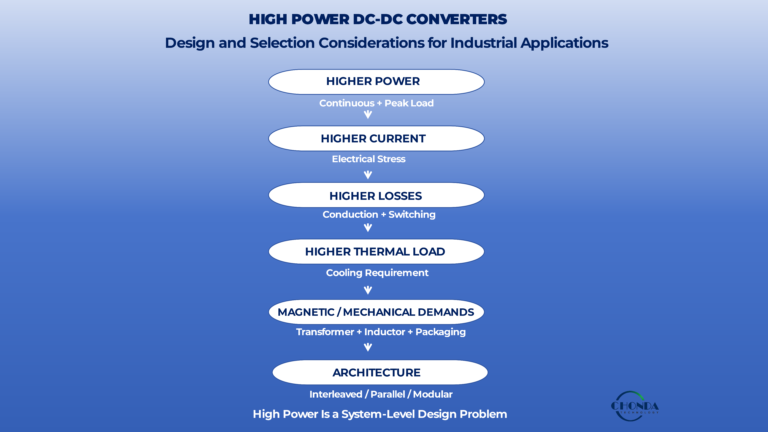
A converter operating across a broad input-voltage range may experience different current levels, switching conditions, conduction losses, and efficiency characteristics as the input voltage changes. These factors affect how much power is dissipated as heat inside the converter.
For this reason, thermal design should be evaluated across the complete expected operating range rather than at only one nominal input condition.
6.1. Power Loss
No DC-DC converter is 100% efficient. The difference between input power and useful output power is dissipated within the converter as power loss.
In simplified form:
Power loss = Input power − Output power
These losses may come from switching devices, magnetic components, rectifiers or synchronous switches, capacitors, PCB conductors, control circuits, and other components.
As converter power increases, even a relatively small percentage of loss can represent a significant amount of heat.
6.2. Heat Generation
Power loss is ultimately converted into heat.
The generated heat must be transferred from the internal components to the surrounding environment. Depending on the converter design, this may occur through the PCB, package, heatsink, enclosure, airflow, or other thermal paths.
If heat cannot be removed effectively, component temperatures can rise beyond their intended operating limits.
Excessive temperature can affect efficiency, component lifetime, electrical characteristics, and long-term reliability.
6.3. Worst-Case Operating Point
The thermal design of a wide-input converter should not assume that the minimum or maximum input voltage is automatically the worst thermal condition.
Different input voltages can produce different combinations of input current, switching behavior, conduction loss, magnetic loss, and control conditions.
The worst thermal condition is not necessarily the lowest or highest input voltage; it depends on the converter topology, switching conditions, load, and efficiency profile.
This is why engineers should identify the actual worst-case operating point through analysis, simulation, component calculations, and, where appropriate, prototype testing.
6.4. Ambient Temperature
Converter temperature is also strongly influenced by the ambient operating environment.
A converter operating at a relatively high ambient temperature has less available temperature margin before its components reach their maximum allowable operating temperatures.
Thermal evaluation should therefore consider realistic ambient conditions rather than relying only on room-temperature laboratory measurements.
For equipment installed inside sealed enclosures, outdoor systems, railway equipment, industrial cabinets, or other thermally constrained environments, ambient temperature can become an important part of the converter design specification.
6.5. Derating
Derating means reducing the allowable operating load or other electrical stress under specified conditions to maintain acceptable thermal and reliability margins.
For example, a converter may be capable of delivering its full rated power under a defined ambient temperature and cooling condition, while a higher ambient temperature may require a lower allowable output power.
Derating requirements depend on the converter design, component ratings, thermal path, cooling method, and application requirements.
Engineers should therefore evaluate the manufacturer’s derating curves and operating limits rather than assuming that the nominal power rating applies under every environmental condition.
6.6. Thermal Resistance
Thermal resistance describes how effectively heat moves from a component or thermal source to its surrounding environment.
Lower thermal resistance generally allows a given amount of dissipated power to produce a smaller temperature rise.
The practical thermal path may include several stages, such as:
Component → PCB → heatsink or enclosure → ambient
The effectiveness of this path depends on component placement, PCB construction, thermal interface materials, mechanical design, airflow, and enclosure conditions.
Thermal resistance should therefore be considered as part of the complete system design rather than treated as an isolated component parameter.
6.7. Cooling
Cooling methods depend on the converter’s power level, physical size, enclosure, ambient conditions, and application environment.
Common approaches include:
- Natural convection
- Forced-air cooling
- PCB-based heat spreading
- Heatsinks
- Thermal interfaces
- Metal enclosures or chassis conduction
For compact embedded converters, PCB layout and heat spreading may be particularly important. For higher-power systems, heatsinks, forced airflow, or chassis-based thermal paths may be required.
The objective is not simply to make the converter run cooler. A good thermal design should maintain component temperatures within their specified limits while preserving the required efficiency, reliability, mechanical constraints, and system performance.
For a wide-input DC-DC converter, thermal performance should therefore be evaluated across the expected combination of input voltage, output load, ambient temperature, and cooling conditions.
This broader operating-envelope approach provides a more realistic assessment of whether the converter can deliver its rated performance reliably in the target application.
7. Wide Input Range and EMI Performance
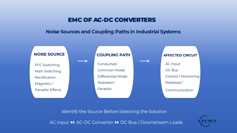
A wide input-voltage range can also affect the electromagnetic interference (EMI) behavior of a DC-DC converter.
As the input voltage changes, the converter’s switching conditions, input current, voltage transitions, and power-stage operating point may also change. These variations can influence both conducted and radiated emissions.
For this reason, EMI performance should be evaluated across the expected input-voltage and load range rather than at only one nominal operating condition.
7.1. Conducted EMI
Conducted EMI travels through electrical conductors such as input power cables, output cables, grounding paths, and other connected circuits.
When the input voltage of a converter changes, the input current and switching behavior may also change. These changes can affect the noise appearing on the input power network.
In practical systems, conducted noise may propagate to controllers, communication interfaces, sensors, or other connected electronic equipment.
Engineers may therefore evaluate conducted EMI under representative low-, nominal-, and high-input conditions to determine whether the input filter and power-stage design provide adequate suppression.
7.2. Radiated EMI
Radiated EMI is electromagnetic energy that couples through space rather than primarily through electrical conductors.
High-voltage switching converters can generate electric and magnetic fields associated with fast voltage and current transitions. PCB layout, transformer construction, switching-node geometry, cable routing, and enclosure design can influence how strongly these fields couple to nearby circuits.
A wide input range does not automatically mean higher radiated emissions. However, changes in operating conditions can alter switching waveforms and current paths, which is why radiated EMI should be considered across the converter’s actual operating envelope.
7.3. Switching Transitions
Switching transitions are an important source of EMI in high-frequency DC-DC converters.
Fast voltage transitions, commonly associated with high dv/dt, and fast current transitions, associated with high di/dt, can increase unwanted capacitive and inductive coupling.
As input conditions change, the converter’s control system may adjust its operating conditions to maintain the required output. Depending on the topology and implementation, this can change switching behavior and the associated electromagnetic noise.
Good EMI design therefore considers not only switching frequency, but also transition speed, current-loop area, switching-node geometry, parasitic capacitance and inductance, and the physical arrangement of high-current paths.
7.4. Input Filter Design
The input filter is an important part of EMI control in a wide-input DC-DC converter.
Its purpose is to reduce high-frequency noise generated by the converter from propagating back into the upstream power source and connected equipment.
However, an input filter should not be selected only according to the nominal input voltage. Engineers should consider:
- Minimum and maximum input voltage
- Expected input current
- Switching frequency and harmonics
- Converter power level
- Filter impedance
- Component current and voltage ratings
- Differential-mode and common-mode noise
- Interaction between the filter and converter control loop
A filter that performs well at one operating point may behave differently under another input-voltage or load condition.
The converter and its input filter should therefore be evaluated as a complete system.
For wide-input applications, EMI performance is best treated as part of the overall converter design rather than as an isolated filtering problem.
📚 Continue Reading
To understand the broader engineering challenges involved in high-voltage DC-DC converter design:
→ High Voltage DC-DC Converter Design Challenges
8. Wide Input DC-DC Converter Protection
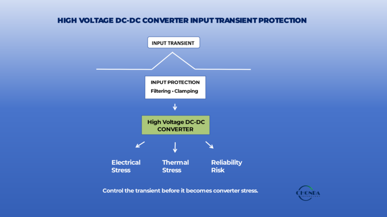
A wide input-voltage range increases the flexibility of a DC-DC converter, but it also requires careful attention to input protection and abnormal operating conditions.
The converter may need to handle not only normal variation between its minimum and maximum operating voltages, but also short-duration voltage disturbances that occur during startup, switching, load changes, battery operation, or other system events.
Protection functions should therefore be evaluated against the actual electrical environment of the application.
8.1. Input Overvoltage Protection
Input overvoltage protection helps protect the converter when the applied input voltage exceeds its specified operating conditions.
An excessive input voltage can increase electrical stress on switching devices, capacitors, magnetic components, and other power-stage components.
Depending on the converter design, overvoltage protection may limit operation, shut down the converter, or use another protective mechanism to prevent excessive stress.
Engineers should verify both the converter’s maximum continuous input voltage and the applicable overvoltage protection thresholds.
8.2. Undervoltage Protection
Undervoltage protection prevents the converter from attempting to operate outside its intended low-input-voltage conditions.
When the input voltage falls below a specified threshold, the converter may no longer be able to maintain the required output power or regulation.
Continuing to operate under severe undervoltage conditions may also cause excessive input current or abnormal switching behavior.
An undervoltage lockout or related control function can therefore prevent the converter from operating in an unstable or potentially damaging condition.
8.3. Surge Protection
A surge is a short-duration increase in voltage that can exceed the normal operating level of the power system.
Surges may be associated with switching events, inductive loads, power-system disturbances, or other transient conditions.
The converter’s ability to withstand or suppress these events depends on its input protection components, topology, insulation system, component ratings, and specified transient requirements.
Surge protection should therefore be evaluated according to the actual system environment rather than inferred from the converter’s normal input-voltage range.
8.4. Transient Voltage
Transient voltage conditions are different from normal continuous operating voltage.
A system may normally operate within a specified range such as 18–75 VDC while experiencing short-duration voltage excursions outside that range.
These events may occur during:
- startup and shutdown
- switching operations
- load changes
- battery charging or discharging
- contactor operation
- braking or regenerative events
- upstream power disturbances
The converter may be designed to tolerate some of these conditions, but the allowable duration, voltage level, and operating state must be verified from the manufacturer’s specifications.
The converter’s continuous operating range and its transient withstand range are not necessarily the same specification.
This distinction is particularly important when selecting a wide-input converter for railway, battery, industrial, telecommunications, and renewable-energy applications.
8.5. Reverse Polarity Protection
Reverse polarity protection protects the converter when the input supply is accidentally connected with the wrong polarity.
This can occur during installation, maintenance, field replacement, or wiring errors.
Depending on the design, reverse-polarity protection may use dedicated protection components, controlled switching devices, or other circuit arrangements to prevent damaging current from flowing through the converter.
Whether reverse-polarity protection is required depends on the application and the risk of incorrect field connection.
8.6. Short-Circuit Protection
Short-circuit protection is primarily associated with abnormal output conditions, but it is an important part of the converter’s overall protection system.
If the output is accidentally shorted, the resulting current can increase rapidly and generate substantial electrical and thermal stress.
A protected converter may limit output current, enter a protection mode, or shut down until the fault condition is removed.
The exact response depends on the converter architecture and protection strategy.
Engineers should therefore verify the short-circuit behavior rather than assuming that every converter provides the same protection response.
8.7. Over-Temperature Protection
Wide-input operation can produce different thermal conditions across the input-voltage and load range.
If internal component temperatures exceed safe operating limits, over-temperature protection (OTP) can reduce the risk of thermal damage.
Depending on the design, OTP may reduce output power, disable switching, or restart the converter after the temperature returns to an acceptable range.
Over-temperature protection should be considered together with thermal resistance, ambient temperature, cooling conditions, and power derating.
Protection should not be treated as a replacement for appropriate thermal design.
8.8. Protection Must Match the Actual Input Environment
A converter’s protection functions should be evaluated as part of the complete application rather than as a simple checklist.
For a wide-input DC-DC converter, engineers should consider:
- minimum and maximum continuous input voltage
- undervoltage conditions
- input overvoltage conditions
- surge events
- transient voltage
- reverse-polarity risk
- output short-circuit conditions
- over-temperature conditions
- required protection response
- duration and frequency of abnormal events
The most important distinction is between what the converter can operate through continuously and what it can survive or tolerate temporarily.
A converter may have a wide continuous operating range while requiring separate specifications for short-duration transient or surge conditions.
Therefore, engineers should always distinguish between the converter’s normal operating envelope and its transient withstand capability when evaluating a wide-input DC-DC converter.
9. How to Choose the Right Wide Input Range
Selecting the right wide-input DC-DC converter should begin with the actual electrical conditions of the system rather than with the converter datasheet alone.
A common mistake is to select a converter based only on the nominal system voltage. For example, a system may be described as a 24 V or 48 V system, but its actual operating voltage can vary substantially around that nominal value.
A more reliable engineering approach is to define the complete input-voltage and operating requirements first, and then select a converter that can satisfy those conditions.
Step 1 — Define the Nominal Voltage
Start by identifying the nominal voltage of the power system.
Examples may include:
- 12 VDC
- 24 VDC
- 48 VDC
- 72 VDC
- Other application-specific DC bus voltages
The nominal voltage provides the starting point for converter selection, but it should not be treated as the complete input specification.
Step 2 — Define the Minimum Voltage
Determine the lowest continuous input voltage that the converter is expected to receive during normal operation.
This may occur during:
- battery discharge
- high system load
- startup
- long cable runs
- power-source variation
- other normal operating conditions
The converter must be able to maintain the required output at this minimum input condition while delivering the required load.
Step 3 — Define the Maximum Voltage
Next, determine the highest continuous input voltage expected during normal operation.
This may occur during:
- battery charging
- light-load conditions
- upstream power variation
- DC-bus regulation
- other normal system conditions
The maximum continuous voltage should remain within the converter’s specified operating range.
Step 4 — Define Transient Conditions
After establishing the continuous operating range, identify transient voltage conditions separately.
These may include:
- surge
- voltage spikes
- voltage dips
- startup transients
- switching events
- regenerative or braking events
- battery or power-system disturbances
The continuous operating range and transient withstand capability should not be treated as the same specification.
Engineers should determine the expected transient voltage, duration, repetition, and source impedance where applicable, and then compare these conditions with the converter’s specified protection and withstand capabilities.
Step 5 — Define the Output Voltage
The required output voltage should be defined based on the actual load electronics.
Common auxiliary output voltages may include:
- 5 VDC
- 12 VDC
- 15 VDC
- 24 VDC
- 48 VDC
The converter should maintain the required output within the specified regulation limits across the expected input and load conditions.
Step 6 — Define the Output Power
Determine the required output power before selecting the converter.
Engineers should consider not only the nominal load, but also:
- maximum continuous load
- startup load
- peak load
- overload conditions
- future system expansion
The converter’s rated power should be evaluated together with its input-voltage range, ambient temperature, cooling conditions, and applicable derating requirements.
A converter with a sufficiently wide input range may still be unsuitable if it cannot provide the required output power under the actual worst-case conditions.
Step 7 — Check Isolation
For isolated DC-DC converters, the required isolation level should be defined according to the system architecture and applicable safety requirements.
Engineers may need to consider:
- isolation voltage
- working voltage
- insulation requirements
- creepage and clearance
- safety standards
- primary-to-secondary fault conditions
Isolation should therefore be evaluated together with the intended application rather than selected solely from a single isolation-test value.
Step 8 — Check Efficiency
Efficiency should be evaluated across the expected input-voltage and load range.
Engineers should examine:
- low-input efficiency
- nominal-input efficiency
- high-input efficiency
- light-load efficiency
- typical operating-load efficiency
- full-load efficiency
Peak efficiency alone does not provide enough information for applications where the input voltage and load vary significantly.
Step 9 — Check Thermal Performance
The converter should also be evaluated under realistic thermal conditions.
Consider:
- ambient temperature
- enclosure conditions
- cooling method
- power loss
- thermal resistance
- component temperature
- derating requirements
The actual worst-case thermal operating point may occur at an intermediate input voltage rather than at the minimum or maximum voltage.
Step 10 — Check EMC / EMI
Finally, engineers should evaluate electromagnetic compatibility across the expected operating envelope.
Important considerations include:
- conducted EMI
- radiated EMI
- switching transitions
- input filtering
- grounding
- shielding
- cable routing
- applicable EMC requirements
A converter that performs well electrically under nominal conditions may still require additional EMC evaluation when input voltage or load conditions change.
Complete Wide Input Converter Selection Flow
The complete engineering selection process can therefore be summarized as:
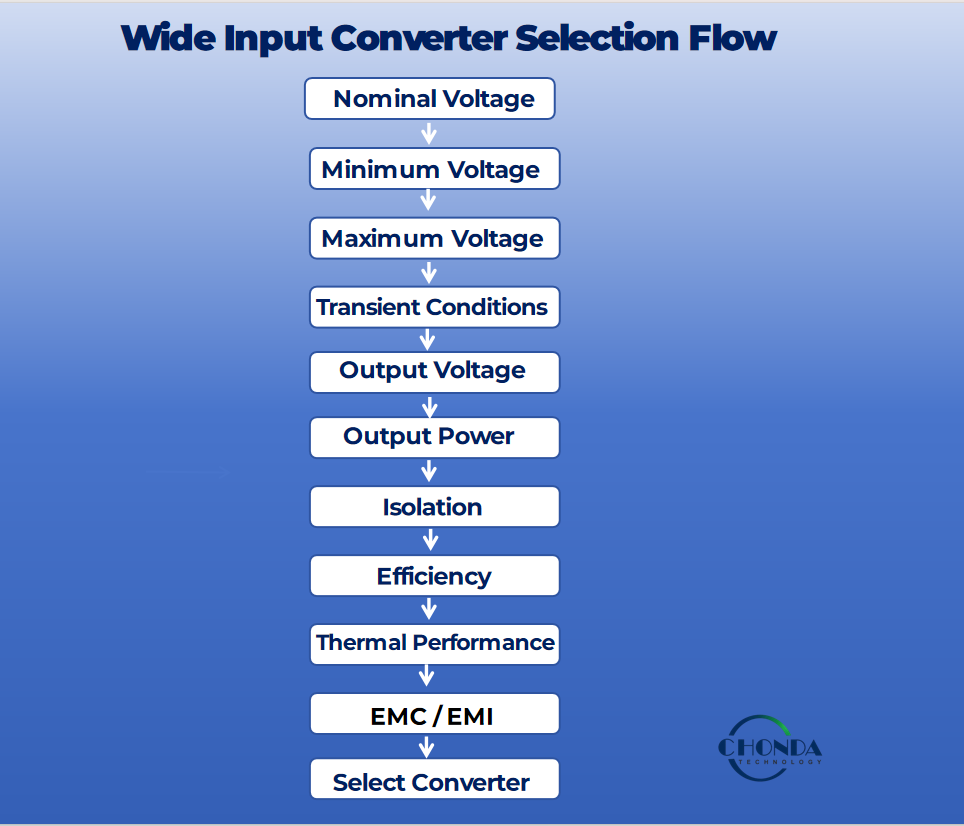
This sequence helps engineers define the actual operating envelope before comparing specific converter models.
The objective is not to select the converter with the widest input range or the highest headline efficiency. The objective is to select a converter whose input range, output performance, isolation, efficiency, thermal behavior, protection, and EMC characteristics match the real requirements of the application.
A correctly selected wide-input DC-DC converter should therefore be evaluated as part of the complete power system rather than as an isolated component.
10. Wide Input Range Does Not Mean Unlimited Input Range
The term wide input range describes a converter’s specified operating capability. It does not mean that the converter can tolerate unlimited input voltage under all conditions.
For example, a converter specified with an input range of 100–1000 VDC is designed to operate within that defined continuous input-voltage range under the conditions stated by the manufacturer.
It does not mean that 1000 V is an unlimited or universal safety boundary for every possible operating condition.
Engineers must distinguish between the converter’s normal operating range and the different voltage conditions that may occur during startup, transients, surges, faults, or other abnormal events.
10.1 Continuous Input Voltage
Continuous input voltage refers to the voltage range within which the converter is designed to operate normally for the specified conditions.
For a converter rated at:
100–1000 VDC
the specified continuous operating range may be understood as:
- Minimum continuous input: 100 VDC
- Maximum continuous input: 1000 VDC
However, the actual allowable output power, ambient temperature, cooling conditions, and other operating limitations may still depend on the manufacturer’s specifications.
A wide input range should therefore always be considered together with the converter’s complete operating conditions.
10.2. Startup Voltage
The voltage required for normal continuous operation is not necessarily identical to every voltage condition encountered during startup.
Depending on the converter architecture, control system, protection strategy, and application, startup behavior may have specific requirements.
Engineers should therefore verify whether the converter can start correctly at the minimum expected input voltage and under the expected load and environmental conditions.
10.3. Transient Voltage
A transient voltage is a short-duration voltage condition that differs from the normal continuous operating voltage.
For example, a system with a continuous input range of 100–1000 VDC may experience a short-duration voltage excursion above or below that range.
Whether the converter can withstand such an event depends on its specified transient capability, protection design, component ratings, event duration, and applicable system requirements.
A transient rating should therefore not be interpreted as an extension of the normal continuous operating range.
10.4. Surge
A surge is a particular type of short-duration overvoltage event that can place significant electrical stress on the converter.
The ability to withstand a surge depends on the converter’s protection components, insulation system, switching devices, capacitors, transformer design, and other factors.
Engineers should evaluate surge requirements separately from the converter’s nominal or continuous input-voltage specification.
10.5. Isolation
Input-voltage range and isolation capability are related but different specifications.
A converter may support a wide input voltage while still having separate requirements for:
- Isolation voltage
- Working voltage
- Creepage
- Clearance
- Insulation system
- Safety standard requirements
Therefore, a wide input range should never be interpreted as evidence that the converter automatically satisfies the required isolation level for a particular application.
10.6. Protection Threshold
Protection thresholds define how the converter responds when electrical conditions move outside its normal operating envelope.
Depending on the design, protection functions may include:
- Input overvoltage protection
- Undervoltage lockout
- Short-circuit protection
- Overtemperature protection
- Overcurrent protection
- Other application-specific protection functions
These thresholds are not necessarily identical to the converter’s maximum continuous input voltage.
For example, a converter may operate continuously up to a specified maximum voltage while a separate protection mechanism responds to a higher abnormal voltage for a limited duration.
10.7. The Engineering Meaning of Wide Input
The correct way to interpret a wide-input specification is therefore:
Wide input means a specified operating range, not unlimited voltage tolerance.
Engineers should distinguish at least the following conditions when evaluating a wide-input DC-DC converter:
Continuous Input
→ Normal operating voltage
Startup Voltage
→ Voltage available when the converter starts
Transient Voltage
→ Short-duration voltage variation
Surge
→ Abnormal short-duration overvoltage
Isolation
→ Insulation and safety requirements
Protection Threshold
→ Converter response to abnormal electrical conditions
These conditions describe different aspects of converter operation and should not be combined into a single input-voltage number.
For this reason, a wide-input DC-DC converter should always be evaluated against the actual electrical environment of the target system, including normal operating conditions, startup behavior, transient events, surge requirements, isolation requirements, and protection limits.
This approach prevents a common engineering mistake: treating the headline input-voltage range as if it were an unlimited tolerance specification.
11. CHONDA Wide Input DC-DC Converter Solutions
CHONDA develops isolated DC-DC converter solutions for applications requiring broad and demanding input-voltage conditions.
Wide-input requirements can vary significantly between applications. Battery systems, railway equipment, industrial automation, telecommunications, renewable-energy systems, and other embedded power architectures may require different combinations of input range, output voltage, power level, isolation, protection, thermal performance, and mechanical integration.
For this reason, CHONDA approaches wide-input DC-DC converter selection from the complete system requirement rather than treating input-voltage range as an isolated specification.
11.1. PHV25 Series
The PHV25 Series provides a standard solution entry point for applications where the required input-voltage range, output voltage, isolation, power level, and mechanical requirements are compatible with the available product specifications.
For a standard application, engineers can first compare the required operating conditions with the corresponding PHV25 product specifications.
If the standard product meets the actual system requirements, a standard converter can provide a more straightforward implementation path.
Related product:
→ PHV25 High Voltage DC-DC Converter Series
11.2. PHV50 Series
For applications requiring a different power level or electrical configuration, the PHV50 Series can provide another standard solution option where the product specifications match the application requirements.
As with any converter selection, engineers should verify the complete operating envelope, including:
- Input-voltage range
- Output voltage
- Output power
- Isolation requirements
- Protection requirements
- Thermal conditions
- Mechanical dimensions
The appropriate product should be selected according to the actual application rather than simply choosing a converter based on its input-voltage range.
Related product:
→ PHV50 High Voltage DC-DC Converter Series
11.3. Custom Wide Input Solutions
Not every wide-input application can be covered by a standard converter.
A custom solution may be appropriate when the required combination of:
- Input-voltage range
- Output voltage
- Isolation
- Output power
- Mechanical dimensions
- Mounting requirements
- Pin definition
falls outside the available standard product specifications.
In these cases, CHONDA can evaluate the application requirements and develop a customized isolated DC-DC converter solution based on the required electrical and mechanical conditions.
The objective is not simply to extend the input-voltage range. A custom converter should be designed around the complete operating envelope of the target system, including efficiency, thermal performance, protection, isolation, EMC, and mechanical integration.
11.4. OEM / Custom Power Solutions
For projects requiring deeper product integration, CHONDA can also support OEM and customized power solutions.
OEM projects may involve requirements such as:
- Customized electrical specifications
- Mechanical integration
- Custom pin definitions
- Customized electrical parameters
- Connector or interface requirements
- Defined annual production volume
- Application-specific reliability requirements
These requirements are typically evaluated together during the project-definition stage.
For higher-volume or application-specific projects, OEM development can provide a more suitable approach than adapting a standard converter to requirements it was not originally designed to meet.
11.5. Selecting the Right CHONDA Solution
The appropriate CHONDA solution depends on how closely the standard product specifications match the actual system requirements.
A practical selection path is:
Standard Requirements
↓
Check PHV25 / PHV50 Specifications
↓
Standard Product Suitable?
↓
Yes → Standard Solution
No → Custom Evaluation
↓
OEM / Custom Power Solution
This approach helps ensure that the selected converter is matched to the actual input-voltage range, output requirements, isolation level, power demand, thermal environment, protection requirements, and mechanical constraints of the application.
For applications where the standard product range does not provide the required combination of specifications, a customized solution can be evaluated with CHONDA.
12. Frequently Asked Questions
Q1. What is a wide input DC-DC converter?
A wide input DC-DC converter is a converter designed to operate normally across a relatively broad specified input-voltage range while providing the required output voltage and power.
The actual operating range is defined by the converter specification and the requirements of the target application.
Q2. What input voltage range is considered wide input?
There is no single universal voltage ratio that defines every wide-input converter.
The appropriate input range depends on the application, power architecture, nominal system voltage, expected voltage variation, and required operating conditions.
For example, a converter operating from 18–75 VDC may be considered wide input for one application, while a much higher voltage range may be required in another system.
Engineers should therefore define the actual system voltage envelope rather than selecting a converter based on a universal wide-input ratio.
Q3. Why do railway systems require wide input DC-DC converters?
Railway systems can experience variations in supply voltage and may also be exposed to transient and abnormal electrical conditions.
A wide-input DC-DC converter can provide greater tolerance to normal supply variation while maintaining a regulated output for onboard electronic equipment.
However, railway converter selection should consider the applicable railway requirements, including nominal voltage, continuous operating conditions, transient conditions, power, isolation, thermal performance, and EMC requirements.
Q4. Does a wider input range reduce converter efficiency?
Not necessarily.
A wider input range provides greater operating flexibility, but converter efficiency can vary across input voltage and load conditions.
At different input voltages, the converter may experience different input currents, switching conditions, conduction losses, magnetic losses, and thermal behavior.
Engineers should therefore evaluate the efficiency curve across the expected input-voltage and load range rather than relying only on peak efficiency.
Q5. How does input voltage affect DC-DC converter thermal performance?
Changes in input voltage can change input current, switching conditions, power losses, and overall converter efficiency.
These changes affect the amount of heat generated inside the converter.
The worst thermal condition is not necessarily the minimum or maximum input voltage. It depends on the converter topology, switching conditions, load, efficiency profile, ambient temperature, and cooling conditions.
Q6. What is the difference between operating range and transient range?
The operating range is the input-voltage range within which the converter is designed to operate normally under specified conditions.
The transient range refers to short-duration voltage conditions that the converter may be designed to withstand or tolerate without damage.
These are not necessarily the same specification.
A converter may operate continuously from 100–1000 VDC while having a separate, higher or lower transient withstand specification with a defined duration and operating condition.
Engineers should always check the manufacturer’s specifications for both continuous operation and transient conditions.
Q7. How do I choose the right wide input DC-DC converter?
Start by defining the complete electrical and environmental requirements of the application.
A practical selection process is:
Nominal Input Voltage → Minimum Voltage → Maximum Voltage → Transient Conditions → Output Voltage → Output Power → Isolation → Efficiency → Thermal Performance → EMC / EMI → Converter Selection
The converter should satisfy the complete operating envelope rather than only the nominal input voltage.
Q8. Can CHONDA provide custom wide input DC-DC converters?
Yes. CHONDA can evaluate custom wide-input DC-DC converter requirements when standard products do not provide the required combination of specifications.
Custom projects may involve requirements for:
- Input-voltage range
- Output voltage
- Output power
- Isolation
- Mechanical dimensions
- Pin definition
- Electrical parameters
- System integration
- Annual production volume
The appropriate solution depends on the actual application requirements and technical specifications.
13. Conclusion
Wide input capability is a system-level engineering feature rather than simply a larger voltage specification.
The correct converter must maintain reliable operation across the required input range while meeting output regulation, efficiency, thermal, protection, isolation, and EMC requirements.
For applications with significant supply variation, selecting the input range from actual system conditions—including nominal voltage, operating limits, and transient conditions—can help prevent unnecessary redesign and improve long-term system reliability.
CHONDA provides standard and customized isolated DC-DC converter solutions for applications requiring defined wide-input operating ranges, including industrial, railway, renewable-energy, telecommunications, and other demanding power systems.
Related Articles
→ Battery Energy Storage (BESS)
→ High Voltage DC-DC Converter for Telecommunication Systems
→ High Voltage DC-DC Converter Design Challenges