We help the world since 2012

Modular High Voltage DC-DC Converters: Benefits, Trade-Offs, and Applications
As high-voltage DC systems become more complex, engineers may need to power multiple loads, voltage domains, or functional subsystems from the same high-voltage source.
A modular DC-DC converter architecture can provide a practical way to divide these power-conversion functions into separate modules rather than designing one large converter to handle every requirement.
A typical modular architecture may look like:
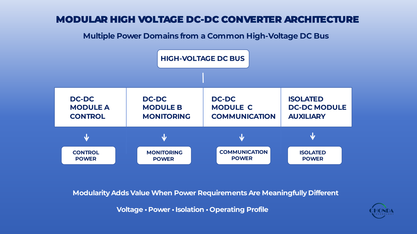
High-Voltage DC Bus → Multiple DC-DC Modules → Control / Monitoring / Communication / Auxiliary Loads
Each module can be designed or selected for a specific electrical role, while the overall system remains connected through a common power architecture.
Modularization can provide several advantages, including:
- Easier system integration
- Greater flexibility in voltage and power requirements
- Simpler development and testing
- Easier maintenance or replacement
- The ability to use different modules for different loads
- Greater flexibility when a system evolves over time
However, modular design also introduces trade-offs.
Additional modules can increase:
- Component count
- Conversion stages
- Total power losses
- EMI sources
- Thermal-management requirements
- Space requirements
- System integration complexity
The most effective modular architecture therefore depends on the actual application rather than on the number of modules used.
This guide examines when modular high-voltage DC-DC converters make sense, how modular architectures can improve system flexibility, and what engineers should consider when balancing modularity against efficiency, thermal performance, EMI, reliability, and overall system complexity.
1. What Is a Modular High-Voltage DC-DC Converter Architecture?
A modular high-voltage DC-DC converter architecture divides the power-conversion functions of a system into multiple converter modules rather than relying on one converter to supply every downstream load.
A simplified architecture can be represented as:
High-Voltage DC Bus → Multiple DC-DC Modules → Different Loads or Power Domains
Each module can provide a defined output voltage, current, power level, or isolation function according to the requirements of the subsystem it supplies.
For example, a high-voltage DC bus may supply several modules:
HV DC Bus → DC-DC Module A → Control Electronics
HV DC Bus → DC-DC Module B → Monitoring Circuit
HV DC Bus → DC-DC Module C → Communication System
HV DC Bus → Isolated DC-DC Module D → Auxiliary Power Domain
Instead of designing one converter around the most demanding combination of all loads, the system can distribute the conversion requirements across multiple modules.
1.1 Modular vs. Single-Converter Architecture
A single-converter architecture may use one power stage to generate the required output or DC bus for the complete system.
A modular architecture separates these functions into multiple conversion stages.
A simplified comparison is:
| Architecture | Basic Structure | Typical Characteristic |
|---|---|---|
| Single Converter | HV DC → One Converter → Multiple Loads | Centralized power conversion |
| Modular | HV DC → Multiple DC-DC Modules → Separate Loads | Distributed power conversion |
The modular approach can be useful when different loads have substantially different power, voltage, isolation, or operating requirements.
1.2 Modules Can Serve Different Functions
Not every module in a modular architecture needs to have the same specification.
For example:
- One module may provide a relatively high-power DC output.
- Another may provide a lower-power control supply.
- One module may require galvanic isolation.
- Another may use a non-isolated architecture.
- Different modules may have different output voltages.
- Some modules may be optimized for monitoring or communication electronics.
This allows the overall system to use the most appropriate conversion characteristics for each functional subsystem.
1.3 A Common High-Voltage DC Bus
Many modular architectures begin with a common high-voltage DC bus.
The bus may be supplied by:
- A battery system
- A photovoltaic DC source
- A BESS DC bus
- An AC-DC front end
- Another upstream DC power system
The individual DC-DC modules then convert the bus voltage into the levels required by downstream circuits.
For example:
High-Voltage DC Bus → 24V Control Supply
High-Voltage DC Bus → Isolated Monitoring Supply
High-Voltage DC Bus → 12V Communication Supply
The exact arrangement depends on the electrical architecture of the equipment.
1.4 Modularity Does Not Mean Complete Independence
Although modules can perform separate functions, they still operate within the same system.
Their interaction may involve:
- Common input-bus behavior
- Shared thermal conditions
- Grounding
- EMI coupling
- Protection coordination
- Startup behavior
- Mechanical constraints
The system must therefore be designed so that the individual modules work together reliably.
A modular architecture should be treated as one system made up of multiple power-conversion building blocks, rather than as several completely independent converters.
1.5 Why Engineers Use Modular Architectures
A modular approach can be attractive when:
- Multiple voltage rails are required.
- Different subsystems have different power requirements.
- Isolation is required for only some loads.
- The system may evolve over time.
- Different equipment versions use different power requirements.
- Development and maintenance flexibility are important.
The main advantage is therefore not simply the number of modules.
The value comes from being able to divide a complex power-conversion problem into smaller, more manageable functional blocks.
However, modularity also introduces additional components, interconnections, losses, and integration requirements. These trade-offs must be considered before deciding that a modular architecture is the best solution for the final equipment.
2. Benefits of a Modular High-Voltage DC-DC Converter Architecture
A modular high-voltage DC-DC converter architecture can provide several practical advantages when an industrial system contains multiple power domains or different types of downstream loads.
The main value of modularization is not simply using multiple converters. It is the ability to divide a complex power-conversion problem into smaller functional blocks that can be designed, tested, and integrated according to the requirements of each subsystem.
2.1 Different Loads Can Have Different Power Requirements
A complex system may contain loads with very different power demands.
For example:
- A control circuit may require only a few watts.
- A monitoring system may require tens of watts.
- An actuator or auxiliary subsystem may require substantially more power.
A modular architecture allows each power domain to use a converter with an appropriate power rating instead of sizing one converter around the maximum combined requirement.
This can help avoid unnecessary oversizing of smaller loads.
2.2 Different Output Voltages Can Be Supported
Industrial equipment often contains multiple DC voltage domains.
A single high-voltage DC bus may therefore need to supply:
24V Control
12V Communication
5V Embedded Electronics
Isolated Monitoring Supply
With a modular architecture, different DC-DC modules can be assigned to these individual voltage requirements.
This can simplify the power distribution strategy and reduce the need to force different loads into one common output architecture.
2.3 Isolation Can Be Applied Where It Is Actually Needed
Not every subsystem necessarily requires galvanic isolation.
A modular design can allow an isolated DC-DC converter to be used for a specific monitoring, measurement, or communication domain while other loads use non-isolated conversion where appropriate.
This can prevent the entire system from being designed around the most restrictive isolation requirement.
The result can be a more targeted power architecture.
2.4 Easier System Development
Modular power stages can simplify development because each conversion function can be evaluated separately.
Engineers may be able to:
- Test individual modules
- Validate one power domain at a time
- Replace a module without redesigning the complete converter
- Compare alternative modules during development
- Reuse a proven module in related equipment
This can reduce the effort required to develop complex power architectures.
2.5 Easier Product Variations
Industrial equipment is often produced in several versions with different electrical requirements.
For example, one equipment model may require:
24V Control + 12V Communication
while another may require:
24V Control + Isolated Monitoring + Additional Auxiliary Power
A modular architecture can make these variations easier to accommodate.
Instead of redesigning the complete power stage, engineers may be able to add, remove, or modify specific conversion modules according to the equipment version.
2.6 Improved Maintainability and Replacement Flexibility
In some applications, modular power architecture can also simplify maintenance.
When a power-conversion function is separated into an identifiable module, troubleshooting can be more structured.
Depending on the equipment design, a service engineer may be able to:
- Identify the affected power domain
- Replace the relevant module
- Reduce system downtime
- Simplify spare-parts management
The actual maintenance benefit depends on whether the modules are physically and electrically replaceable in the final equipment.
2.7 Reuse of Proven Power Modules
A modular architecture can also support reuse.
Once a high-voltage DC-DC module has been validated for a specific voltage range, power level, isolation requirement, or environmental condition, the same basic module may be considered for other equipment that has compatible requirements.
This can reduce repeated development effort and create a more consistent power architecture across related products.
2.8 Better Separation of Power Functions
Modularization can help separate different power-conversion functions according to their roles.
For example:
High-Voltage DC Bus
↓
Power Module A — Main Control
Power Module B — Monitoring
Power Module C — Communication
Power Module D — Isolated Auxiliary Supply
This functional separation can make the overall architecture easier to analyze and modify.
However, the modules still share the same system environment. Their combined behavior must therefore be evaluated at the system level.
2.9 Modularity Can Improve Design Flexibility
The strongest benefit of modularization is often flexibility.
A modular power architecture can make it easier to:
- Scale power requirements
- Support multiple voltage rails
- Add isolated power domains
- Develop product variants
- Reuse validated modules
- Adapt the system to changing requirements
This flexibility is particularly valuable when the final equipment is expected to evolve over time.
2.10 Modularity Is Valuable When It Solves a Real System Problem
A modular architecture should not be selected simply because multiple modules appear easier to use.
The decision should be based on whether the benefits of separating the power functions outweigh the additional components and integration work.
The most useful question is therefore:
Does modularization make the complete power architecture simpler, more flexible, or easier to maintain?
When the answer is yes, a modular high-voltage DC-DC architecture can provide significant value in industrial power systems.
3. Trade-Offs of a Modular High-Voltage DC-DC Converter Architecture
Although modular power architectures can improve flexibility and simplify the management of multiple power domains, they also introduce additional design and integration challenges.
Using several DC-DC modules does not automatically make a power system simpler. Each additional module creates another power-conversion stage that must be evaluated as part of the complete system.
The right question is therefore not simply whether a modular architecture is possible, but whether its advantages justify the additional complexity.
3.1 More Conversion Stages Can Increase Total Losses
When several conversion modules are used, each module introduces its own conversion losses.
For example:
HV DC Bus → Module A → Load A
HV DC Bus → Module B → Load B
may be an efficient architecture when the loads require different voltage domains.
However, if multiple unnecessary conversion stages are introduced, the total system losses can increase.
The additional losses may come from:
- Switching
- Conduction
- Magnetic components
- Control circuits
- Input and output filtering
The number of conversion stages should therefore be minimized where they do not provide a meaningful system benefit.
3.2 Component Count Increases
A modular architecture generally requires more individual components than a single integrated power stage.
Each module may require its own:
- Input filtering
- Output filtering
- Protection
- Control circuitry
- Connectors
- Mounting structure
- Thermal path
As the number of modules increases, the overall bill of materials and assembly requirements can also increase.
Modularity should therefore provide a clear functional benefit that justifies the additional hardware.
3.3 System Integration Becomes More Important
Individual modules may operate correctly when tested separately but behave differently when connected to the same high-voltage bus.
Engineers may need to consider:
- Input-bus interaction
- Startup sequencing
- Grounding
- Protection coordination
- Current sharing where applicable
- Transient behavior
- Control interactions
The system must therefore be evaluated as a complete architecture rather than assuming that independently tested modules will automatically work together.
3.4 EMI Sources Can Increase
Each switching converter can generate high-frequency electrical activity.
Adding more modules can therefore increase the number of potential noise sources within the equipment.
The combined system may contain multiple:
- Switching nodes
- Current loops
- Gate-drive circuits
- Magnetic components
- High-frequency return paths
This does not mean that modular systems are inherently difficult to manage from an EMI perspective.
It means that the modules must be positioned and integrated so that their combined electromagnetic behavior remains acceptable.
Detailed EMI design is discussed in High Voltage DC-DC Converter EMI Design Considerations.
3.5 Thermal Integration Can Become More Complex
Multiple converters also generate heat in multiple locations.
Instead of managing the heat from one centralized converter, the mechanical system may need to handle several distributed heat sources.
This can affect:
- Heat-sink placement
- Airflow
- PCB temperature
- Enclosure temperature
- Component spacing
- Local thermal density
A modular system may therefore simplify electrical functions while making thermal integration more complex.
3.6 Space and Mechanical Requirements
Using separate modules can require more physical space for:
- Module bodies
- Connectors
- Wiring
- Mounting hardware
- Isolation distances
- Cooling structures
A modular architecture is most attractive when the flexibility gained from separate modules is more valuable than the additional mechanical space they require.
3.7 More Interfaces Mean More Potential Failure Points
Every additional connector, cable, mounting interface, or inter-module electrical connection introduces another point that must be designed and verified.
Engineers should consider:
- Connector reliability
- Cable losses
- Mechanical vibration
- Contact resistance
- Insulation
- Serviceability
The physical interfaces between modules can therefore become an important part of overall reliability.
3.8 Protection Coordination
Multiple modules operating from a common high-voltage bus may have different protection thresholds and fault responses.
A system designer may need to coordinate:
- Input protection
- Over-current limits
- Short-circuit behavior
- Startup behavior
- Shutdown behavior
- Recovery sequences
A fault in one power domain should ideally not create unnecessary instability in unrelated power domains.
Protection should therefore be considered at both the module level and system level.
3.9 Cost Can Increase
Modular architecture can reduce development effort and improve flexibility, but it may also increase the cost per complete system if many separate modules are required.
The total cost should therefore include:
- Modules
- Connectors
- Filtering
- Mechanical structures
- Cooling
- Wiring
- Assembly
- Testing
- Maintenance
A modular solution is economically attractive when its flexibility and development benefits outweigh these additional system costs.
3.10 Modularity Should Have a Clear Purpose
The main lesson is that modularization should solve a real system problem.
A modular architecture can be valuable when it provides:
Flexibility + Reuse + Multiple Power Domains + Easier Maintenance
But it can become unnecessarily complex when it introduces:
More Modules + More Losses + More Interfaces + More Thermal and EMI Challenges
The best architecture is therefore not the one with the greatest number of modules.
It is the architecture that provides the right level of modularity for the electrical and application requirements of the system.
4. When Is a Modular Architecture the Better Choice?
A modular high-voltage DC-DC architecture becomes attractive when the electrical system contains multiple loads or power domains that have meaningfully different requirements.
The key reason to introduce separate converter modules is not simply to divide the hardware into smaller pieces. The real benefit is that each power-conversion function can be matched more closely to the load it serves.
For example, a high-voltage DC bus may supply a control system, a monitoring circuit, and a communication interface. These subsystems may require different output voltages, different power levels, or different isolation conditions. Designing one converter to satisfy the most demanding combination of all three can create unnecessary complexity. A modular architecture allows the engineer to treat these requirements separately.
4.1 Multiple Voltage Domains
A modular architecture is particularly useful when one high-voltage source needs to provide several DC voltage levels.
A system may require 24V for control electronics, 12V for communication equipment, and a separate isolated supply for measurement or monitoring circuits.
Instead of forcing all of these functions into one complex conversion stage, individual DC-DC modules can be assigned to the power domains that actually need them.
This can make the overall architecture easier to understand and easier to modify when the system requirements change.
4.2 Different Power Levels
Modularity can also make sense when the downstream loads have very different power requirements.
Suppose one subsystem requires only 10W while another requires 100W. A single converter sized around the combined maximum load may be physically and economically inefficient, particularly if the smaller loads have very different operating characteristics.
With a modular architecture, each converter can be selected according to the requirements of its own load.
This does not automatically reduce total system cost or power loss, but it can prevent one small load from being tied to the requirements of a much larger power stage.
4.3 Selective Isolation
Another strong use case is when only some parts of the system require galvanic isolation.
For example, control electronics may share the same DC reference as the main bus, while a monitoring or measurement circuit may need an isolated power domain.
A modular architecture allows the isolated conversion stage to be used only where it provides a real system benefit.
This can be simpler than designing the entire power architecture around the most restrictive isolation requirement.
4.4 Product Families and Different Equipment Versions
Modularity becomes even more useful when a company develops several equipment versions based on a similar platform.
One version may require only a control supply.
Another may add monitoring electronics.
A third may require an isolated communication interface or an additional auxiliary voltage.
If the power architecture is modular, these variations can sometimes be accommodated by changing only the relevant power-conversion modules rather than redesigning the entire power stage.
This can help reduce repeated engineering work and make validated power solutions easier to reuse across related products.
4.5 Systems That Are Expected to Evolve
Modular architecture can also be useful when the final requirements are likely to change.
Industrial products are often developed over multiple revisions, and new sensors, controllers, communication interfaces, or auxiliary functions may be added later.
A centralized converter architecture can become difficult to modify when every new requirement affects the original power stage.
A modular architecture can provide more flexibility because additional conversion functions can be evaluated independently, provided that the common DC bus, thermal system, protection strategy, and mechanical structure can support the change.
4.6 When a Single Converter May Still Be Better
Modularity is not automatically the better solution.
If a system has one main DC load with a well-defined voltage and power requirement, introducing several smaller converters may add unnecessary hardware and integration work.
A single converter may be preferable when:
- The output requirements are straightforward.
- One power domain serves most of the system.
- Isolation requirements are uniform.
- Mechanical space is limited.
- Additional conversion stages would provide little functional benefit.
The decision should therefore be based on the architecture of the equipment, not on the number of available converter modules.
4.7 A Practical Decision Principle
A modular high-voltage DC-DC architecture is most useful when different parts of the system have different power-conversion requirements.
The strongest reasons to consider modularization are usually:
Multiple Voltage Domains + Different Power Levels + Selective Isolation + Product Flexibility
When these conditions are present, separate converter modules can turn a complex power-conversion problem into a set of more manageable functional blocks.
When these conditions are not present, a simpler single-converter architecture may provide better efficiency, lower cost, and easier integration.
The objective is therefore not to maximize modularity.
It is to choose the simplest architecture that provides the required flexibility and performance for the complete system.
5. How Modularity Affects System Efficiency
One of the most important questions when evaluating a modular high-voltage DC-DC architecture is whether dividing the power-conversion functions across multiple modules will reduce overall system efficiency.
The answer depends on how the modules are used.
A modular architecture can improve the efficiency of a system when it allows each converter to operate closer to the conditions for which it is designed. On the other hand, unnecessary conversion stages can increase total power loss.
The engineering objective is therefore not to minimize or maximize the number of modules. It is to place the right conversion stages in the right parts of the power architecture.
5.1 A Module Can Be Better Matched to Its Load
Consider a system in which one high-voltage DC bus supplies several loads.
A single converter may need to support a wide combination of requirements, including a relatively high-power load and several much smaller auxiliary loads. In some cases, this can force the converter to operate over a wider range than is ideal for any one load.
With a modular architecture, the main load can use a converter sized for its own requirements while smaller subsystems use separate modules.
This does not guarantee higher efficiency, but it can make it easier to choose converters that operate within practical and well-understood load ranges.
5.2 Unnecessary Conversion Stages Increase Losses
The opposite can also happen.
Every additional DC-DC conversion stage introduces its own losses.
For example, if a DC bus already provides a suitable voltage for a control circuit, converting it through another intermediate voltage before reaching the load may provide no meaningful benefit.
A simplified example is:
HV DC → DC-DC A → DC Bus → DC-DC B → Load
If the intermediate conversion performed by DC-DC A is not required for the rest of the system, the additional stage may simply introduce more losses, components, and thermal load.
In such a case, a more direct architecture may be preferable.
5.3 Modularity Works Best When the Power Domains Are Meaningfully Different
The strongest case for modularization is usually when the loads are genuinely different.
For example, a system might contain:
HV DC Bus → 24V Control
HV DC Bus → Isolated Monitoring
HV DC Bus → 12V Communication
These are not merely three copies of the same power requirement. They may have different output voltages, isolation requirements, power levels, noise sensitivities, and operating profiles.
Using separate modules can therefore provide a clearer architectural solution than forcing all of these functions into one centralized conversion stage.
5.4 Efficiency Should Be Evaluated at the System Level
Comparing two individual module efficiency figures is not enough to determine which architecture is better.
Engineers should consider:
Source → Conversion Stages → Distribution → Loads
The relevant question is how much power is ultimately delivered to the required loads compared with the power drawn from the original source.
For example, a modular architecture containing several highly efficient modules may still consume more energy than a simpler single-stage architecture if the modular system contains unnecessary conversion stages.
Likewise, a slightly less efficient individual module may contribute to a better overall system if it eliminates another conversion stage or allows a major power domain to be designed more effectively.
5.5 Light-Load Operation Can Change the Comparison
The way each module is loaded also matters.
Suppose a system contains a small monitoring circuit that operates most of the time at low power. A dedicated module may provide excellent control and isolation, but its own light-load losses still contribute to the total system consumption.
In another design, that same monitoring function could be supplied from an existing regulated rail with fewer conversion stages.
The better solution depends on the actual operating profile, not simply on the rated efficiency of each module.
This is particularly relevant for industrial monitoring and embedded systems that may spend long periods at relatively low power.
5.6 Modularity Can Improve Efficiency Indirectly
The benefits of modularization are not limited to conversion efficiency.
A modular architecture can sometimes improve the overall system by allowing engineers to separate functions that have different thermal, voltage, or operating requirements.
For example, a sensitive monitoring circuit may be placed on a dedicated isolated module rather than sharing a more heavily loaded power stage.
This can simplify grounding, reduce unwanted interactions, and make it easier to optimize each power domain.
The resulting system may be more reliable or easier to integrate even when the difference in raw conversion efficiency is small.
5.7 A Practical Engineering Trade-Off
The relationship can be summarized as:
More Modules
→ Greater Flexibility
→ More Independent Power Domains
→ Potentially Better Load Matching
but also:
→ More Conversion Stages
→ More Components
→ More Total Loss Opportunities
This means that modularity should be introduced where it provides a clear functional advantage.
A well-designed modular architecture may use several modules because each one solves a different problem.
A poorly designed modular architecture may use several modules simply because modular components are convenient to combine.
The distinction is important.
5.8 The Right Question Is Not “How Many Modules?”
When evaluating a modular high-voltage DC-DC architecture, engineers should ask:
Does each module perform a necessary function that would otherwise make the system more complex, less flexible, or less reliable?
If the answer is yes, the additional conversion stage may be justified.
If the answer is no, the simpler architecture may be the better engineering choice.
Modularity should therefore be evaluated according to the complete power path, load profile, thermal environment, and functional requirements of the equipment.
The best modular architecture is not the one with the most modules. It is the one in which each conversion stage has a clear purpose and contributes meaningful value to the overall system.
6. Modular Architecture and System Integration
A modular high-voltage DC-DC converter architecture can simplify individual power-conversion functions, but integrating several modules into one system requires careful coordination.
Each module may perform correctly when tested independently. However, once multiple converters share the same high-voltage bus, enclosure, grounding structure, and cooling environment, their interactions can influence the behavior of the complete power system.
This is why modularity should be viewed as a system architecture decision, not simply a collection of independent converter modules.
6.1 The Shared DC Bus Becomes a Common System Environment
When multiple modules are supplied from the same high-voltage DC bus, they share the electrical conditions of that bus.
A change in one module can therefore affect the environment seen by the others.
For example, a module that produces a temporary increase in input current may cause a voltage disturbance on a weak or highly resistive DC bus. Another module connected to the same bus may then experience an input transient or temporary voltage variation.
The design should therefore consider the characteristics of the common bus, including its:
- Voltage range
- Source impedance
- Wiring
- Protection
- Capacitance
- Transient behavior
The bus is not simply a connection point. It is part of the electrical behavior of the entire modular architecture.
6.2 Startup and Shutdown Should Be Considered Together
Multiple power modules may not start and stop at exactly the same time.
This can create situations where one module is already operating while another is still starting, or where several modules draw startup current simultaneously.
For example:
HV DC Bus → Module A → Control
HV DC Bus → Module B → Monitoring
HV DC Bus → Module C → Communication
If all three modules start simultaneously, the combined startup demand may be very different from the steady-state load.
Engineers may therefore need to consider startup sequencing, soft-start behavior, input capacitance, and protection thresholds at the system level.
6.3 Protection Must Be Coordinated
Each module may have its own over-current, over-voltage, thermal, or short-circuit protection.
However, the protection behavior of one module can influence the common DC bus and therefore affect other modules.
For example, a faulted module that repeatedly enters restart mode may create repeated disturbances on the shared input bus.
The system designer should therefore consider not only whether each module has protection, but also how the modules behave when faults occur at the same time.
A reliable modular system should ideally isolate a local fault without creating unnecessary instability in unrelated power domains.
6.4 Grounding and Reference Points Become More Important
Different modules may have different grounding and isolation arrangements.
One module may share a system reference, while another may provide an isolated output for a monitoring or communication circuit.
These relationships should be defined before the modules are connected into the final equipment.
Poorly planned reference connections can create:
- Unintended current paths
- Ground loops
- Noise coupling
- Unexpected voltage differences
- Isolation problems
The electrical reference of each module should therefore be considered as part of the system architecture rather than left to the final wiring stage.
6.5 Physical Placement Matters
Modules that operate independently from an electrical perspective may still influence each other through physical proximity.
For example, several high-frequency converters installed close together may create overlapping electromagnetic fields or share thermal paths within the same enclosure.
Placement should therefore consider:
- Switching-node proximity
- Magnetic coupling
- Airflow
- Heat sources
- Connector routing
- High-voltage spacing
A modular architecture gives engineers flexibility in where the conversion stages are placed, but that flexibility must be used carefully.
6.6 Thermal Integration Is a System Problem
Each module produces its own heat, but the final enclosure must remove the combined thermal load.
Suppose three modules each dissipate a modest amount of power. Individually, each module may remain within its specified temperature range.
If all three are installed next to one another in a poorly ventilated enclosure, however, their local ambient temperature may rise significantly.
The actual thermal condition should therefore be considered as:
Module Losses + Module Placement + Airflow + Enclosure Temperature
This is particularly important when several high-power modules operate continuously.
6.7 EMI Can Become a Combined-System Problem
Multiple switching converters can also create a more complex electromagnetic environment.
Even when each module satisfies its own EMI requirements, the combined system may contain:
- Several switching frequencies
- Multiple high-dv/dt nodes
- Multiple current loops
- Multiple common-mode paths
These signals can interact through shared power, grounding, or mechanical structures.
The system layout should therefore be reviewed as a complete electromagnetic environment.
Detailed EMI mitigation techniques are covered in High Voltage DC-DC Converter EMI Design Considerations, while PCB implementation considerations are discussed in High Voltage DC-DC Converter PCB Design Considerations.
6.8 Mechanical Integration Should Be Planned Early
A modular architecture can make electrical development easier while simultaneously making mechanical integration more complicated.
Each additional module may require its own:
- Mounting arrangement
- Connector
- Heat-spreading path
- Isolation spacing
- Service access
These requirements should be considered before the enclosure and PCB layout are finalized.
Otherwise, engineers may discover that an electrically suitable module cannot be installed efficiently within the available physical space.
6.9 Design the Modules as One Power System
The main principle is that modularity should simplify functional design without fragmenting system-level engineering.
A practical integration review should therefore consider:
Common DC Bus → Startup → Protection → Grounding → EMI → Thermal → Mechanical Integration
The individual converter modules remain separate functional blocks, but the final equipment should be evaluated as one coordinated power system.
When this system-level integration is done correctly, modular high-voltage DC-DC architectures can provide flexibility without sacrificing reliability or controllability.
7. How Much Modularity Does the System Really Need?
Modularization can make a high-voltage DC-DC power architecture more flexible, but more modularity does not automatically produce a better design.
A system with many independent converter modules may be highly configurable, yet it can also become more difficult to manage in terms of efficiency, thermal performance, EMI, mechanical integration, cost, and maintenance.
The practical engineering question is therefore not:
How many modules can the system use?
It is:
Which power-conversion functions benefit from being separated?
7.1 Separate a Function When Its Requirements Are Meaningfully Different
A strong reason to create a separate module is when a subsystem has requirements that are substantially different from the rest of the equipment.
For example, suppose a high-voltage DC system contains:
- A main control system
- A sensitive measurement circuit
- A communication interface
If the measurement circuit requires galvanic isolation and very different noise conditions from the control electronics, separating that power domain can provide a clear architectural benefit.
The same principle applies when one load requires substantially more power than the others.
In these situations, the additional module is not simply another converter. It represents a genuinely different electrical function.
7.2 Avoid Splitting Closely Related Loads Without a Clear Benefit
Not every load requires its own converter.
For example, if several low-power control circuits operate from the same voltage, have similar grounding requirements, and have similar operating profiles, placing them on one appropriately designed power module may be simpler than assigning a separate module to each circuit.
Excessive subdivision can increase:
- Component count
- Wiring
- Interfaces
- Conversion losses
- Mechanical space
- System testing effort
A good modular architecture therefore separates functions where the separation adds value, while keeping closely related loads together where practical.
7.3 The Main DC Bus Can Be the Natural Boundary
A useful way to determine the right level of modularity is to identify the major power domains in the system.
For example:
High-Voltage DC Bus
↓
Main Control Power
Monitoring Power
Communication Power
Auxiliary Power
Each of these may or may not deserve an independent converter.
The decision depends on whether the power domain has different requirements for voltage, power, isolation, noise, operating profile, or future flexibility.
The DC bus can therefore serve as a natural architectural boundary from which individual conversion functions are distributed.
7.4 Consider Future Product Variants
The right level of modularity can also depend on whether the equipment will be produced in one fixed configuration or as a family of related products.
If every product version requires exactly the same power architecture, adding many independent modules may create unnecessary complexity.
However, if one model requires an additional monitoring system while another does not, modularization can make the platform easier to adapt.
For example:
Base Platform
→ Control Module
and then optional modules:
→ Monitoring Module
→ Communication Module
→ Additional Isolated Power Module
In this situation, modularity can provide real value because it supports product variation without requiring the entire power architecture to be redesigned.
7.5 Consider the Service and Maintenance Strategy
The level of modularity should also reflect how the equipment will be serviced.
A dedicated module can make troubleshooting easier when the affected power domain is clearly separated from the others.
However, excessive modularization can create the opposite problem if technicians must diagnose many individual modules, connectors, and interfaces.
The maintenance strategy should therefore be considered alongside the electrical architecture.
7.6 Modularity and Reliability
Modularization can improve reliability when it isolates functions and limits the impact of local faults.
For example, a fault in a dedicated monitoring power module may be easier to isolate from the main control power supply.
However, each additional module also adds components and interfaces that can potentially fail.
Reliability therefore depends on the quality of the architecture rather than on the number of modules alone.
A useful engineering principle is:
Functional Separation Where It Adds Value + Simplicity Where It Does Not
7.7 A Practical Test for Modularity
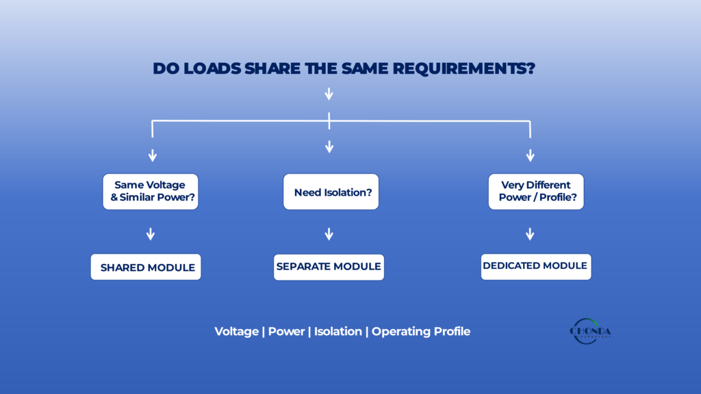
Before creating a separate converter module, engineers can ask:
Does this load have a different voltage requirement?
Does it require different power capability?
Does it require galvanic isolation?
Does it have a significantly different operating profile?
Does separating it simplify development, maintenance, or future product variation?
If several of these conditions apply, a dedicated module may be justified.
If none of them apply, combining the load with an existing power domain may produce a simpler solution.
7.8 The Goal Is Appropriate Modularity
The best modular architecture is rarely the one with the largest number of independent converters.
It is the architecture in which each module has a clear reason to exist.
A well-designed system may contain only two or three modules, while another complex system may reasonably require many more.
The correct level of modularity is determined by the functional structure of the equipment, the electrical requirements of each power domain, and the long-term needs of the product.
Ultimately, modularity should make the system easier to design, easier to adapt, and easier to maintain without introducing unnecessary conversion stages or integration complexity.
8. Standard Modules vs. Customized Modular Solutions
One of the practical advantages of a modular high-voltage DC-DC architecture is the possibility of using proven standard power modules as building blocks.
However, a standard module is not always the best choice for every power domain. Some applications can be designed efficiently around existing modules, while others may require modifications to meet unusual electrical, mechanical, thermal, or isolation requirements.
The decision should therefore be based on how well the available module fits the actual function it needs to perform.
8.1 When a Standard Module Fits the Architecture
A standard module can be a strong choice when the power requirements of a subsystem already fall within an available product range.
For example, a monitoring circuit may require a defined high-voltage DC input, a regulated 24V output, and a relatively stable power level.
If an existing module already provides the required:
- Input range
- Output voltage
- Power capability
- Isolation
- Protection
- Mechanical format
then using a standard module can significantly reduce development effort.
The engineering team can focus on system integration instead of redesigning the entire conversion stage.
8.2 Standard Modules Can Support Platform-Based Design
Modular architectures become particularly effective when the same standard module can be reused across several related products.
For example, a company may develop several industrial equipment versions using the same high-voltage DC bus.
One product may require a control supply, another may add monitoring electronics, and a third may include an isolated communication subsystem.
If the same validated DC-DC module can be used across these products, the development team may reduce repeated design work while maintaining a more consistent power architecture.
This is one of the strongest practical arguments for combining modularity with standardized power modules.
8.3 When a Standard Module Does Not Fit Perfectly
A standard module may still be technically usable while creating unnecessary compromises elsewhere in the system.
For example, the available module may have:
- A wider power rating than necessary
- A mechanical format that does not fit the enclosure
- An input range that only partially matches the actual DC bus
- Connector positions that complicate PCB routing
- Thermal characteristics that are difficult to accommodate
In such cases, engineers need to compare the cost of adapting the surrounding system with the cost and time required to modify the module itself.
The cheapest solution is not always the one with the lowest module price.
8.4 Modified Standard Modules Can Be a Practical Middle Ground
Some applications do not require a completely new converter.
A proven platform may already provide the required power-conversion architecture, while only a few parameters need to change.
For example, the application may require a different:
Input Voltage Range
or:
Output Voltage
or:
Mechanical Configuration
or:
Thermal Arrangement
A modified standard platform can sometimes provide a useful balance between development speed and application-specific requirements.
The advantage is that the underlying power-conversion architecture may already be proven, while the design is adapted to the actual equipment.
8.5 When a Custom Module Becomes More Valuable
A customized modular solution becomes more attractive when the system requirements cannot be matched efficiently by available standard products.
This may occur when several constraints appear at the same time.
For example, an industrial application may require a combination of:
- Very wide high-voltage input range
- Specific low-voltage output
- Defined isolation performance
- Restricted PCB space
- Unusual cooling conditions
- Application-specific protection
- Specialized connector arrangements
Trying to combine several standard modules or redesign the surrounding equipment to accommodate them may create more complexity than developing a dedicated power module.
In such cases, customization can be a system-level optimization rather than simply a product-level modification.
8.6 The Modular Architecture Should Still Come First
It is important not to start the design by asking:
Which standard module do we have?
A better process is:
Define the Power Domains → Define Their Requirements → Determine the Modular Architecture → Select Standard or Customized Modules
This prevents the available product catalog from determining the architecture before the actual system requirements are understood.
A standard module should support the architecture.
The architecture should not be forced to fit an unsuitable module merely because the module already exists.
8.7 Modularity Can Reduce Customization Requirements
A well-designed modular architecture can sometimes reduce the amount of customization needed.
Instead of developing one highly complex converter that performs every function, engineers may use standard modules for the majority of the system and customize only the power domain that has unusual requirements.
For example:
Standard Module → Main Control
Standard Module → Communication
Customized Isolated Module → Specialized Monitoring
This approach can concentrate engineering effort where it provides the most value.
8.8 A Practical Selection Principle
The decision can be summarized as:
Standard Module
→ Best when the requirements already match an existing platform.
Modified Standard
→ Best when the architecture is suitable but selected parameters need adjustment.
Custom Module
→ Best when the application requirements cannot be addressed efficiently with standard or modified products.
The important point is that modularity gives engineers more ways to structure the solution.
It does not mean that every module must be custom-made.
8.9 The Goal Is a Practical Power Platform
For industrial equipment, the strongest modular architecture is often the one that combines:
Proven Standard Modules + Targeted Customization + Clear Power-Domain Separation
This approach can reduce development effort while preserving the flexibility needed for specialized applications.
The final decision should consider not only the module itself, but also the cost, time, reliability, thermal performance, mechanical integration, and long-term scalability of the complete power system.
A successful modular architecture is therefore one in which standardization is used where it simplifies the system, while customization is applied where it creates meaningful engineering value.
9. Applications of Modular High-Voltage DC-DC Converter Architectures
Modular high-voltage DC-DC converter architectures are particularly useful in systems where one high-voltage DC source must supply several electronic subsystems with different power, voltage, isolation, or operating requirements.
The advantage of modularization becomes easier to understand when it is viewed from the perspective of the equipment rather than the converter itself.
A single high-voltage DC bus can serve as the common power source, while individual converter modules create the power domains required by different parts of the system.
9.1 PV Monitoring Systems
PV monitoring systems are a practical example of why modular power conversion can be useful.
A photovoltaic system may expose monitoring electronics to a relatively high DC voltage while the individual control, measurement, communication, and sensing circuits require much lower regulated voltages.
A modular architecture can separate these functions.
For example:
High-Voltage PV DC → DC-DC Module → Control Electronics
while another module may provide:
High-Voltage PV DC → Isolated DC-DC Module → Measurement / Monitoring
This approach can allow the monitoring and communication functions to be designed around their actual electrical requirements without forcing all subsystems into one common power-conversion stage.
For broader PV string monitoring applications, see PV String Monitoring Power Supply and related PV monitoring resources.
9.2 Battery Energy Storage Systems
Battery energy storage systems can contain high-voltage DC buses together with battery management, monitoring, communication, control, and protection electronics.
Different subsystems may require different voltage levels or isolation conditions.
A modular architecture can therefore provide a common DC input while allowing individual power domains to be handled separately.
For example:
BESS DC Bus → Main Control Power
BESS DC Bus → Isolated Monitoring Power
BESS DC Bus → Communication Power
This can be useful when the system is expected to evolve or when different equipment versions require different combinations of auxiliary functions.
9.3 Industrial Automation
Industrial automation systems often combine controllers, sensors, communication interfaces, measurement devices, and other electronic subsystems.
These functions do not necessarily have identical power requirements.
A modular architecture can allow the main control system to use one converter while a separate module supplies communication, measurement, or isolated auxiliary circuits.
This can make it easier to adapt the power architecture when the equipment is expanded or when different versions of the machine require different electronic functions.
9.4 Robotics and Embedded Systems
Robotic and embedded systems often operate from batteries or DC buses and can contain multiple voltage domains.
A typical system may require power for:
- Control electronics
- Sensors
- Communication
- Embedded processors
- Actuators or auxiliary systems
A modular DC-DC architecture can separate these power requirements when their voltage, power, or isolation needs are significantly different.
This can be especially useful when mechanical space is limited and the power architecture needs to evolve as the equipment becomes more capable.
9.5 Monitoring and Measurement Equipment
Measurement systems can be particularly sensitive to electrical noise and grounding conditions.
A dedicated isolated DC-DC module can provide a separate power domain for measurement electronics while other parts of the equipment operate from a common DC bus.
This separation does not automatically eliminate noise problems, but it can give engineers greater control over the electrical relationships between power and measurement circuits.
9.6 Complex Industrial Power Systems
Some industrial systems combine several of the above functions within one piece of equipment.
For example:
High-Voltage DC Bus
↓
Main Control Module
Monitoring Module
Communication Module
Isolated Auxiliary Module
This architecture allows the system designer to treat each power domain according to its actual requirements.
The result can be a more flexible platform, particularly when different equipment configurations need different combinations of functions.
9.7 When Modularity Creates the Most Value
Across these applications, modularization tends to provide the greatest value when several of the following conditions are present:
- Multiple DC voltage domains
- Different power levels
- Selective isolation requirements
- Different operating profiles
- Product variations
- Limited development resources
- A need to reuse validated power-conversion functions
The value comes from separating requirements that are meaningfully different rather than simply increasing the number of converters.
9.8 How CHONDA Power Modules Can Fit These Architectures
CHONDA’s power-module portfolio can be considered within this type of modular architecture for industrial applications where different DC power domains need to be created from a common source.
Depending on the application, this may involve:
- High-voltage DC-DC power modules
- Isolated DC-DC modules
- AC-DC power modules as front-end stages
- Transformer-based power solutions
- Customized power modules for non-standard electrical or mechanical requirements
For applications such as PV monitoring, industrial automation, robotics, and other specialized equipment, the appropriate module configuration depends on the system’s input voltage, output requirements, isolation, thermal conditions, mechanical constraints, and expected operating environment.
The purpose of a modular architecture is not to use as many CHONDA modules as possible. It is to determine where a separate power-conversion function provides a meaningful technical or system-level advantage.
This distinction is important when evaluating standard modules, modified platforms, and customized solutions for a complete industrial power architecture.
10. Modular Architectures for PV Monitoring, BESS, and Industrial Systems
The most appropriate modular power architecture depends on how the high-voltage DC source is distributed through the equipment and how the downstream power domains are organized.
PV monitoring systems, battery energy storage systems, and industrial equipment may all use high-voltage DC-DC conversion, but the reasons for using multiple modules can be quite different.
The following examples illustrate how the same modular concept can lead to different system architectures.
10.1 PV Monitoring: Separate the Monitoring Power Domain
In a PV monitoring system, the high-voltage DC source may be available directly from the photovoltaic string or another part of the PV electrical architecture.
The monitoring electronics, however, may require a relatively low and stable DC supply.
A simplified modular architecture could be:
High-Voltage PV DC → DC-DC Module → Monitoring Electronics
If the measurement circuit has additional isolation requirements, a separate isolated module may be considered:
High-Voltage PV DC → Isolated DC-DC Module → Measurement / Monitoring
The important architectural decision is whether the monitoring electronics can share the same power domain as the control system or whether they benefit from a dedicated isolated supply.
For PV applications, this decision can affect not only voltage conversion but also insulation, grounding, EMI, and physical integration.
10.2 BESS: Separate Control, Monitoring, and Communication Functions
A BESS can present a different modularization challenge because the system may contain several continuously operating auxiliary functions around a high-voltage battery bus.
A simplified architecture might be:
High-Voltage Battery Bus
↓
DC-DC Module A → Control Electronics
DC-DC Module B → Monitoring / BMS-Related Electronics
DC-DC Module C → Communication / Auxiliary Electronics
The value of this arrangement depends on whether the subsystems have sufficiently different requirements to justify separation.
For example, a communication circuit that requires only a small amount of power may not need a dedicated converter if it can safely operate from an existing regulated rail.
On the other hand, a monitoring or measurement domain with different isolation requirements may justify a separate module.
The architectural question is therefore not simply how many loads exist, but which loads should belong to the same power domain.
10.3 Industrial Systems: Build Around Functional Power Domains
Industrial equipment often provides the greatest flexibility in modular architecture because one machine may contain several distinct electrical functions.
For example:
High-Voltage DC Bus
↓
Main Control Power
Sensor / Measurement Power
Communication Power
Isolated Auxiliary Power
The modules do not necessarily need to have identical ratings.
One may be optimized for higher continuous power, while another may be designed for low-power isolated operation.
This allows engineers to match each power stage more closely to the actual function it supports.
10.4 When a Common DC Bus Is the Better Architecture
A common DC bus can be advantageous when several modules need to operate from the same high-voltage source.
It can simplify the distribution of the primary power while allowing the individual modules to perform local voltage conversion.
For example:
HV DC Bus → Module A / Module B / Module C
can be easier to expand than a system in which each subsystem requires a completely independent front-end power path.
However, the common bus must be designed to handle the combined electrical and transient behavior of the connected modules.
10.5 When Separate Power Domains Are Better
In some systems, keeping two functions on separate power domains can provide important advantages.
This may be appropriate when:
- One subsystem requires galvanic isolation.
- One load is particularly sensitive to noise.
- Two circuits operate at substantially different voltages.
- One subsystem has very different startup or shutdown behavior.
- A fault should be isolated from another power domain.
For example:
HV DC Bus → Main Control Module
and separately:
HV DC Bus → Isolated Monitoring Module
can provide a clearer electrical boundary than attempting to power both functions from the same output.
10.6 Avoiding an Overly Fragmented Architecture
The opposite problem is creating too many independent modules.
Suppose an industrial system has five low-power loads that all require the same 24V supply and share similar operating conditions.
Giving each load its own DC-DC converter may provide little additional value while increasing:
- Conversion losses
- Wiring
- Interfaces
- Space requirements
- Cost
- Maintenance effort
A more practical architecture may be:
HV DC Bus → One 24V DC-DC Module → Multiple Related Loads
The decision should therefore be based on functional differences, not simply on the number of loads.
10.7 Comparing the Three Architecture Patterns
The three applications illustrate different approaches.
| Application | Typical Modular Pattern | Main Architectural Question |
|---|---|---|
| PV Monitoring | HV DC → DC-DC / Isolated DC-DC → Monitoring | Does monitoring require a separate or isolated power domain? |
| BESS | HV Battery Bus → Multiple DC-DC Modules | Which auxiliary functions should share a power domain? |
| Industrial Systems | HV DC Bus → Functional Power Modules | How should control, sensing, communication, and auxiliary power be separated? |
These are not fixed architectures. The appropriate arrangement depends on the actual equipment requirements.
10.8 A Common Design Principle
Across PV, BESS, and industrial systems, the same principle applies:
Start with the Power Domains, Not the Modules
First determine:
- What voltage each subsystem requires
- How much power it needs
- Whether isolation is necessary
- Whether loads should share the same supply
- Which functions need independent protection or fault isolation
Only after these questions are answered should the engineer decide how many converter modules are required.
This approach prevents the product catalog from determining the system architecture and helps ensure that modularization provides a real technical benefit.
A well-designed modular system therefore uses different architectures for different applications while preserving the same underlying principle:
Separate power-conversion functions when the separation creates meaningful electrical, functional, or system-level value.
11. Common Modular Power Architecture Mistakes
A modular high-voltage DC-DC architecture can provide flexibility, but poor modularization can also create unnecessary complexity.
Many problems do not come from a failure of an individual converter. Instead, they arise because the relationship between multiple modules was not considered carefully during the system design.
A useful modular architecture should therefore be evaluated as a complete power system rather than as a collection of independent modules.
11.1 Creating a Separate Module for Every Load
One common mistake is assuming that every load should have its own converter.
In practice, several low-power loads may have the same voltage, similar operating profiles, and compatible grounding requirements.
For example, if several control circuits all require a stable 24V supply, using one appropriately sized 24V DC-DC module may be simpler than providing a separate converter for each circuit.
Over-fragmenting the architecture can increase cost, wiring, interfaces, losses, and maintenance effort without providing a meaningful technical benefit.
The better approach is to separate power domains when their requirements are genuinely different.
11.2 Using Modules Without Defining the Power Domains First
Another mistake is selecting modules before deciding how the equipment should be divided into power domains.
Engineers may find several suitable modules in a product catalog and begin connecting them together without first answering:
Which circuits should share a supply, and which circuits should remain electrically independent?
This can lead to an architecture that works electrically but is unnecessarily difficult to manage.
The power domains should therefore be defined first, based on voltage, power, isolation, noise sensitivity, operating profile, and fault behavior.
11.3 Ignoring the Common DC Bus
When several modules share the same high-voltage DC bus, their combined behavior becomes part of the system design.
A module that starts, stops, or changes load can affect the bus voltage seen by other modules.
If the source impedance, wiring, protection, or bus capacitance is not considered, unexpected voltage disturbances may appear during startup or transient events.
A modular architecture should therefore be evaluated under realistic combined operating conditions.
11.4 Assuming Independently Tested Modules Will Automatically Work Together
A converter can operate correctly during standalone testing and still create problems after it is integrated with other converters.
For example, several modules may interact through:
- Shared input impedance
- Common grounding
- Startup behavior
- Switching noise
- Thermal conditions
This is particularly important when modules from different designs or suppliers are combined.
System-level testing is therefore necessary even when each individual module has already been validated.
11.5 Ignoring Fault Interaction
A local failure in one module should not unnecessarily destabilize unrelated power domains.
For example, if one monitoring converter enters repeated short-circuit recovery while sharing the same high-voltage bus with the main control converter, its fault behavior could affect the stability of the other power stages.
Protection should therefore be evaluated at two levels:
Module Protection
and
System Protection
The goal is to ensure that a fault remains as local as practical.
11.6 Adding Modules Without Considering Thermal Distribution
A modular architecture can distribute power conversion across several modules, but this also distributes heat generation.
If several modules are installed in the same enclosure, their combined heat can increase the local ambient temperature.
A module that operates safely by itself may therefore require derating after it is installed beside other heat-producing converters.
The thermal design should consider the complete enclosure rather than the temperature of each module in isolation.
11.7 Ignoring EMI Interaction Between Modules
Multiple switching converters can also create a more complicated electromagnetic environment.
Different modules may have different switching frequencies and edge rates, while their current and return paths may overlap through the common power architecture.
This can create unexpected coupling between power domains even when the modules perform correctly individually.
The system should therefore be reviewed for:
- Shared current paths
- Common-mode coupling
- Physical proximity
- Grounding
- Filtering
- Switching-node interaction
Detailed EMI design belongs to the dedicated EMI and PCB articles, but the modular architecture should establish the right physical and electrical boundaries first.
11.8 Choosing Modules Solely by Individual Specifications
A module with excellent efficiency, high power density, or a wide input range may still be the wrong choice for the complete system.
For example, one converter may have an attractive specification but require a mechanical format or cooling arrangement that conflicts with the rest of the equipment.
The correct question is not:
Is this a good converter?
It is:
Is this the right converter for this power domain within this system?
This distinction becomes increasingly important as more modules are introduced.
11.9 Forgetting Future Product Changes
A modular architecture is often selected partly because it can support future changes.
However, engineers sometimes create a modular structure that is technically flexible but mechanically or electrically difficult to expand.
For example, there may be no available mounting space, insufficient DC-bus capacity, or no practical method of adding another isolated power domain later.
When modularity is intended to support future product variants, the likely evolution of the system should be considered from the beginning.
11.10 Treating Modularity as the Objective
The biggest mistake is treating modularity itself as a design goal.
A system is not necessarily better because it contains more independent modules.
The real purpose of modularization is to make the system easier to design, adapt, maintain, or optimize.
A practical architecture should therefore ask:
What function does each module perform?
Why is this function separated from the others?
What system-level benefit does that separation provide?
If there is no clear answer, the additional module may not be justified.
11.11 A Better Modular Design Principle
The most effective modular high-voltage DC-DC architecture can be summarized as:
Define Power Domains → Separate Meaningfully Different Functions → Select Appropriate Modules → Integrate the Common Bus → Validate the Complete System
This approach keeps modularity focused on solving real engineering problems rather than adding complexity for its own sake.
A well-designed modular architecture should ultimately make the power system more understandable, more adaptable, and more maintainable without creating unnecessary conversion stages or interfaces.
12. How to Evaluate a Modular High-Voltage DC-DC Power Architecture
A modular high-voltage DC-DC architecture should ultimately be evaluated as a complete power system rather than by comparing the specifications of individual converter modules.
The central question is whether dividing the power-conversion functions into separate modules provides a meaningful advantage for the equipment being developed.
A practical evaluation should begin with the structure of the power system and then consider how each module contributes to the overall electrical, thermal, mechanical, and operational requirements.
12.1 Start with the Power Domains
Before selecting individual converters, identify the main power domains within the equipment.
For each subsystem, determine:
- Required input source
- Output voltage
- Continuous and peak power
- Isolation requirements
- Operating conditions
- Load profile
- Fault behavior
This step establishes whether the system genuinely contains multiple power-conversion functions or whether several loads could reasonably share one common power domain.
12.2 Identify Which Functions Should Be Separate
Once the power domains are defined, determine which functions benefit from being separated.
For example, a monitoring circuit may require isolation that the main control circuit does not need.
A communication subsystem may require a different output voltage but only a small amount of power.
A high-power auxiliary load may have a completely different thermal and current requirement from the rest of the electronics.
These differences provide a technical reason to consider separate modules.
If several loads have essentially the same electrical requirements, keeping them within the same power domain may provide a simpler solution.
12.3 Evaluate the Common DC-Bus Architecture
When several modules share a high-voltage DC bus, the bus becomes a key part of the system design.
Engineers should consider how the modules behave together during:
- Startup
- Shutdown
- Load changes
- Fault conditions
- Input-voltage disturbances
The source, wiring, protection, capacitance, and impedance of the bus can influence the behavior of every connected module.
A modular architecture should therefore be evaluated using the actual expected bus conditions rather than treating each converter as completely independent.
12.4 Compare System-Level Efficiency
The efficiency of individual modules should not be evaluated in isolation.
Instead, compare the complete power path.
For example:
HV DC → One Conversion Stage → Load
may be preferable to:
HV DC → Module A → Intermediate DC Bus → Module B → Load
if Module A does not provide a necessary function.
On the other hand, if Module A creates a common DC domain that serves several downstream functions, the additional stage may be justified.
The best architecture is therefore the one that provides the required functions with the fewest unnecessary conversion stages.
12.5 Evaluate Thermal Distribution
Thermal performance should be assessed at the system level.
Instead of asking only whether each module can operate at its rated temperature, engineers should consider where heat is generated and how it moves through the complete enclosure.
For example, three moderate-power modules placed close together may create a more difficult thermal environment than one larger converter with a dedicated heat-spreading structure.
The evaluation should therefore include:
Module Losses → Module Placement → Heat Spreading → Airflow → Enclosure Temperature
This is especially important in compact industrial equipment where there is limited space for cooling.
12.6 Review EMI and Electrical Interaction
A modular architecture can create multiple switching and return-current paths.
Engineers should therefore examine how the modules interact through:
- Shared input paths
- Ground references
- Common-mode coupling
- Switching-node proximity
- Filtering
- PCB layout
The objective is not to eliminate switching activity but to ensure that the overall architecture provides controlled electrical and electromagnetic boundaries.
12.7 Consider Mechanical and Service Requirements
A modular architecture should also be evaluated from the perspective of the final equipment.
The design team should ask:
Can the modules be mounted, cooled, connected, tested, and serviced efficiently?
For a production product, this can be just as important as the electrical specifications.
A modular system that is electrically elegant but difficult to assemble or service may not provide a practical commercial advantage.
12.8 Evaluate Scalability and Reuse
One of the strongest reasons for modularization is the possibility of reusing validated power-conversion functions across different equipment versions.
The architecture should therefore be evaluated for whether it can support:
- Different output requirements
- Additional monitoring functions
- New communication interfaces
- Different power levels
- Product variants
- Future upgrades
A module that can be reused across several related systems may provide greater value than its initial electrical specification suggests.
12.9 Compare Standard, Modified, and Custom Approaches
The final evaluation should also consider the level of product customization required.
A useful comparison is:
Standard Modules
→ Fastest path when requirements already match.
Modified Standard
→ Useful when the architecture is proven but selected parameters need adjustment.
Custom Modules
→ Appropriate when several system requirements fall outside standard solutions.
This decision should be made after the power architecture is understood, not before.
12.10 A Practical Evaluation Framework
A modular high-voltage DC-DC architecture can be reviewed using the following sequence:
Power Domains
↓
Module Boundaries
↓
Common DC Bus
↓
Efficiency
↓
Thermal
↓
EMI
↓
Mechanical Integration
↓
Protection
↓
Serviceability
↓
Scalability
↓
Standard / Modified / Custom
The purpose of this review is not to prove that modularization is always better.
It is to determine whether the modular architecture creates enough technical and business value to justify the additional modules and integration effort.
12.11 The Final Engineering Question
Before approving a modular high-voltage DC-DC architecture, the engineering team should be able to explain three things clearly:
Why does each module exist?
What system-level problem does it solve?
Would combining or removing that module make the system meaningfully better or worse?
If these questions have clear answers, the modular architecture is likely based on real system requirements rather than on the convenience of assembling independent power modules.
The strongest modular power architectures are therefore not the most complicated ones.
They are the ones in which each module has a clear function, the interfaces are controlled, and the complete system benefits from the separation of power-conversion tasks.
Conclusion
A modular high-voltage DC-DC converter architecture can provide significant flexibility when an industrial system contains multiple power domains with different voltage, power, isolation, or operating requirements.
The main advantage of modularization is not simply the use of multiple converters. It is the ability to divide complex power-conversion requirements into functional blocks that can be designed, tested, reused, and adapted according to the needs of the complete system.
At the same time, each additional module introduces its own power losses, interfaces, thermal load, EMI considerations, mechanical requirements, and protection behavior.
A practical modular architecture should therefore balance:
Functional Separation + Flexibility + Reuse
with:
Efficiency + Thermal Performance + EMI + Cost + Integration Complexity
The most effective approach is to define the required power domains first, determine which functions genuinely benefit from separation, and then select the appropriate combination of standard, modified, or customized DC-DC modules.
For PV monitoring, battery energy storage, industrial automation, robotics, embedded electronics, and other high-voltage DC systems, modular power conversion can be valuable when it solves a real system-level problem.
The objective is not to maximize the number of converter modules.
It is to create a power architecture in which each module has a clear purpose and the complete system benefits from the separation of power-conversion functions.
How CHONDA Supports Modular High-Voltage DC-DC Architectures
CHONDA provides high-voltage DC-DC power modules and application-specific power solutions for industrial systems that require defined input ranges, regulated outputs, electrical isolation, compact integration, or customized electrical and mechanical configurations.
Depending on the application, CHONDA solutions can be considered as individual building blocks within a larger modular power architecture or as part of a customized power-conversion system.
For applications with non-standard input ranges, output requirements, thermal conditions, isolation requirements, or mechanical constraints, CHONDA can evaluate the system requirements and determine whether a standard module, modified platform, or customized solution is more appropriate.
Related Articles
What Is a High Voltage DC-DC Converter?
Understand the basic principles, architecture, and applications of high-voltage DC-DC converters for industrial power systems.
How to Select a High Voltage DC-DC Converter Module for Industrial Applications
Learn how input range, output requirements, power, isolation, thermal conditions, and application requirements influence module selection.
DC-DC Converter Selection Guide: Key Parameters for High Voltage Applications
Review the major electrical and application parameters engineers should evaluate when selecting a high-voltage DC-DC converter.
High Voltage Power Supply Design Guide
Explore a system-level framework for power architecture, isolation, regulation, EMI, thermal management, protection, PCB design, and power-module selection.
High Voltage DC-DC Converter Thermal Management
Understand how power losses, temperature rise, cooling, and derating affect high-voltage DC-DC converter reliability.
High Voltage DC-DC Converter EMI Design Considerations
Explore switching noise, common-mode and differential-mode noise, grounding, filtering, and other EMI considerations.