We help the world since 2012

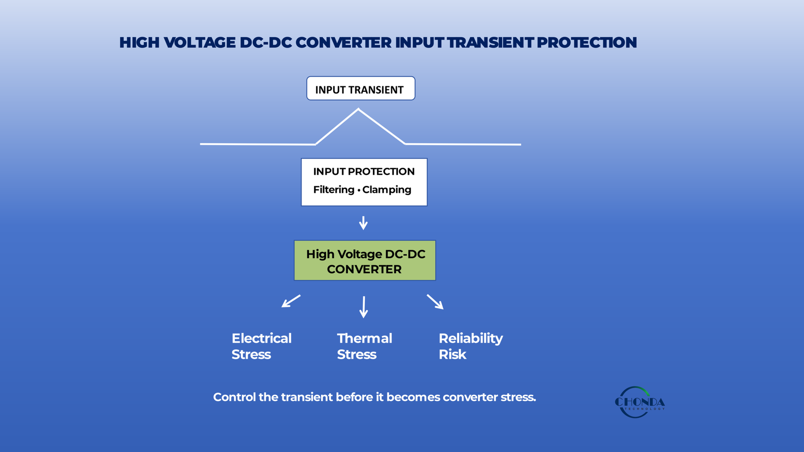
High Voltage DC-DC Converter Input Transient Protection: What Engineers Should Consider
A high voltage DC-DC converter may be specified for a wide input-voltage range, but the nominal operating range does not always represent the complete electrical environment seen at the converter input.
In industrial power systems, the DC input can experience short-duration voltage disturbances caused by switching events, rapid load changes, wiring effects, regenerative energy, upstream power conversion, or other system-level conditions.
These input transients can expose the converter and its input components to voltage levels or rates of change that are significantly different from normal steady-state operation.
For a high voltage DC-DC converter, this can create additional stress on input capacitors, switching devices, protection components, insulation structures, and control circuits.
The practical challenge is therefore not simply to ask whether a converter supports a specified input voltage.
It is to determine whether the converter can tolerate the actual transient environment of the system.
A suitable protection strategy should be based on the magnitude, duration, repetition, source impedance, and expected energy of the transient, together with the converter’s own input protection capability.
This article explains where high voltage DC input transients can come from, why they matter, how engineers can evaluate the actual transient environment, and what to consider when selecting or designing protection for a high voltage DC-DC converter.
The goal is to establish a practical principle:
Input-voltage range defines normal operation; transient protection addresses what happens outside the normal operating point.
1. What Is an Input Transient in a High Voltage DC-DC System?
Before selecting an input protection strategy, it is important to distinguish between the voltage conditions a high voltage DC-DC converter is designed to operate under normally and short-duration disturbances that occur outside those conditions.
In a practical DC power system, the converter input voltage is rarely perfectly constant. The voltage may vary with operating conditions, load changes, source characteristics, wiring, or upstream power electronics.
However, not every change in input voltage should be considered a transient.
1.1 Steady-State Input Voltage
Steady-state voltage refers to the relatively stable input voltage present during normal operation.
For example, a converter may be specified for a nominal input such as 400VDC, 800VDC, or a wide operating range such as 200–1200VDC. Within that range, the input voltage may change gradually as the power system operating point changes.
These changes are part of the converter’s expected operating environment.
A simplified example is:
Normal operating condition:
800VDC → 780VDC → 820VDC → 790VDC
The voltage is changing, but it remains within the expected operating range and changes relatively gradually.
The converter’s normal regulation, control, thermal behavior, and efficiency are generally evaluated under these steady-state operating conditions.
1.2 Normal Input Voltage Variation
A normal input-voltage variation is a change in the DC input that occurs during ordinary system operation but does not represent a short-duration disturbance.
The exact boundary between normal variation and a transient depends on the application and the converter specification.
For example, an industrial DC bus may gradually rise or fall because of:
- changes in the upstream power source
- changes in system load
- battery state or charging conditions
- operating-point changes in a power conversion system
The key characteristic is that the converter has sufficient time to respond to the change through its normal control and regulation mechanisms.
Therefore:
Normal input variation is part of the operating condition; it is not necessarily a protection event.
1.3 What Is an Input Transient?
An input transient is a short-duration voltage disturbance that occurs over a much shorter time scale than a normal operating change.
The voltage may rise sharply, fall sharply, or exhibit an oscillatory or ringing behavior before returning toward the normal operating condition.
A simplified example is:
Normal DC bus:
800VDC
Transient event:
800VDC → sudden voltage spike → 1050VDC → back toward 800VDC
The important point is not simply that the voltage becomes higher or lower.
The transient is characterized by factors such as:
- Magnitude — how far the voltage moves from the normal operating point
- Duration — how long the disturbance lasts
- Rate of change — how quickly the voltage changes
- Repetition — whether the event occurs once or repeatedly
- Energy — how much electrical energy is associated with the disturbance
These characteristics determine how much stress the converter input stage and associated components may experience.
A transient therefore should not be treated simply as “an unusually high input voltage.”
It is better understood as a short-duration electrical disturbance superimposed on the normal DC input condition.
1.4 Transient vs. Normal Input Variation
The distinction can be summarized as follows:
| Condition | Typical Behavior | Converter Perspective |
|---|---|---|
| Steady-state voltage | Relatively stable | Normal operating point |
| Normal input variation | Gradual or expected change | Part of normal operation |
| Input transient | Fast, short-duration disturbance | Abnormal electrical stress |
This distinction is important because a converter can have a sufficiently wide normal input-voltage range and still require additional consideration for input transients.
For example, a converter rated for a wide input range does not automatically mean that any short-duration voltage spike above that range can be tolerated indefinitely.
The specified operating range answers one question:
What input voltage can the converter normally operate from?
Transient capability answers a different question:
What short-duration disturbance can the converter survive without unacceptable electrical or functional stress?
1.5 Why the Distinction Matters for High Voltage DC-DC Converters
This distinction becomes particularly important at high input voltages.
A short-duration voltage spike can place additional electrical stress on components that may already operate close to their normal voltage limits. Depending on the converter architecture, this may affect:
- input capacitors
- switching devices
- surge or clamping components
- insulation structures
- control and sensing circuits
- PCB creepage and clearance regions
Therefore, engineers should evaluate normal input range and transient environment separately.
A suitable high voltage DC-DC converter should not only match the required steady-state input voltage. Its input stage should also be appropriate for the actual transient conditions expected in the complete system.
Normal input range defines where the converter operates.
Transient conditions define what the converter may experience during abnormal short-duration events.
This distinction provides the basis for the next step: identifying where these high voltage DC input transients actually come from in industrial and power-conversion systems.
2. Where Do High Voltage DC Input Transients Come From?
High voltage DC input transients can originate from many parts of a power system rather than from the DC-DC converter itself.
In an industrial system, the converter is connected to a larger electrical network that may include batteries, upstream converters, switching devices, cables, loads, and protection equipment. Changes occurring anywhere in this network can appear at the converter input.
Understanding the source of the transient is therefore an important first step in determining whether additional input protection is required.
2.1 Switching Events in the DC Power System
One common source of input transients is the switching of high-power electrical equipment.
When a switch, contactor, semiconductor device, or other switching element changes state, the voltage at the DC bus can change rapidly. The effect depends on factors such as the circuit inductance, switching speed, source impedance, and the characteristics of the connected equipment.
For a high voltage DC-DC converter, this event may appear as a short-duration voltage spike or ringing at the input terminals.
The disturbance may be particularly noticeable when high-energy circuits are switched on or off.
Therefore:
Fast switching can create short-duration voltage disturbances even when the steady-state DC bus voltage remains within the converter’s normal operating range.
2.2 Rapid Load Changes
A sudden change in load can also disturb a high voltage DC bus.
For example, a large downstream load may be connected, disconnected, or change its power demand rapidly. The upstream power system and wiring cannot always respond instantaneously, so the DC bus voltage may temporarily deviate from its normal value.
Depending on the system architecture, this can produce either a temporary overvoltage or undervoltage condition.
The converter therefore needs to be evaluated not only at the nominal input voltage, but also during realistic load-transition events.
2.3 Wiring and Cable Inductance
The physical wiring between the power source and the converter can also influence transient behavior.
Cables and bus structures have parasitic inductance and resistance. When current changes rapidly, these parasitic elements can contribute to voltage overshoot or ringing.
This means that a converter connected to a remote DC source may experience a different transient environment from a converter connected directly to the same source with very short wiring.
The electrical behavior of the complete source-to-converter path therefore matters.
2.4 Upstream Power Conversion Equipment
Many high voltage DC-DC converters are not connected directly to a simple DC source.
They may be supplied from:
- battery systems
- rectifiers
- PFC stages
- bidirectional converters
- energy-storage systems
- motor-drive or other power-conversion equipment
The switching and control behavior of these upstream stages can influence the voltage seen by the DC-DC converter.
For example, changes in operating mode, control-loop response, or energy flow may cause temporary disturbances on the shared DC bus.
The converter should therefore be evaluated as part of the overall power architecture rather than as an isolated component.
2.5 Regenerative Energy and Energy Flow Reversal
Some industrial systems can return energy to the DC bus rather than continuously consuming energy from it.
This may occur during regenerative operation, braking, motor deceleration, or other changes in energy flow.
When electrical energy is returned to the DC bus, the bus voltage can temporarily increase depending on the system’s ability to absorb or dissipate that energy.
For a high voltage DC-DC converter, this creates a particularly important question:
Can the converter input stage tolerate the resulting temporary overvoltage, and for how long?
The answer cannot be determined from nominal input voltage alone.
2.6 Battery and Energy-Storage Systems
Battery-powered systems can also produce input disturbances.
Although batteries generally provide a relatively stable DC source, the voltage seen by the converter can change during charging, discharging, switching, protection events, or changes in system operating conditions.
In larger energy-storage systems, multiple converters and protection devices may also interact with the common DC bus.
As a result, the converter input environment may include both normal battery-voltage variation and short-duration transient events.
2.7 External Disturbances and System-Level Events
Not all transients originate from equipment operating immediately next to the converter.
A disturbance elsewhere on a shared DC bus can propagate through the power distribution network and reach the converter input.
This is particularly relevant in systems where several converters, loads, switching devices, or energy-storage components share the same electrical bus.
Therefore, transient protection should be considered at the system level, including the source, distribution network, converter, and connected loads.
2.8 A Practical View of Transient Sources
The main sources can be summarized as follows:
| Transient Source | Typical Mechanism | Possible Input Effect |
|---|---|---|
| Switching events | Rapid change of circuit state | Voltage spike or ringing |
| Load changes | Sudden change in power demand | Temporary overvoltage or undervoltage |
| Cable/wiring effects | Parasitic inductance and resistance | Overshoot or oscillation |
| Upstream converters | Switching and control response | DC-bus disturbance |
| Regenerative energy | Energy returned to DC bus | Temporary overvoltage |
| Battery/energy-storage events | Operating or protection changes | Input-voltage disturbance |
| Shared DC-bus events | Disturbance from other equipment | Transient reaching converter input |
The important point is that the converter does not need to be the source of a transient to be affected by it.
A high voltage DC-DC converter is often one part of a much larger electrical system. The transient environment at its input is determined by the interaction between the power source, wiring, switching devices, energy-storage elements, loads, and converter architecture.
This leads to the next engineering question: what actually happens inside the converter when these transient events reach its input, and why can even a short-duration disturbance create long-term reliability problems?
3. Why Input Transients Are a Problem for High Voltage DC-DC Converters
A high voltage DC-DC converter is designed to operate within a defined electrical and environmental range. During normal operation, the input stage, switching devices, insulation structures, and control circuits are exposed to voltages and currents that remain within their specified conditions.
An input transient is different.
Even when the disturbance lasts for only a short period, a sudden change in input voltage can create electrical stress that is significantly higher than that experienced during normal steady-state operation.
The actual impact depends on the transient magnitude, duration, repetition rate, source impedance, and the converter’s internal architecture.
3.1 Voltage Stress on Input Components
The first concern is the additional voltage stress placed on components connected directly to the converter input.
Depending on the converter design, these components may include:
- input capacitors
- switching devices
- protection components
- filtering components
- voltage-sensing circuits
- insulation-related structures
A component that operates safely at the converter’s normal input voltage may experience substantially greater electrical stress during a transient.
For example, a converter operating from an 800VDC bus may normally remain well within its specified operating range, while a short-duration overvoltage can temporarily increase the voltage across components in the input stage.
Therefore:
Component voltage rating should be considered together with the actual transient environment, not only the nominal DC input voltage.
3.2 Stress on Switching Devices
High voltage DC-DC converters rely on switching devices to process electrical energy.
During an input-voltage transient, the voltage appearing across these devices can change rapidly. Depending on the circuit topology and parasitic elements, the actual device stress may be influenced by both the external input disturbance and internal switching behavior.
This can result in:
- higher peak voltage
- increased switching stress
- additional losses
- electrical overstress during repeated events
A single event may not immediately cause component failure.
However, repeated transient exposure can contribute to gradual degradation and reduce long-term reliability.
3.3 Stress on Input Capacitors and Filtering Components
Input capacitors are particularly important because they are directly connected to the DC input environment.
During an overvoltage transient, the voltage applied to the capacitor can temporarily exceed its normal operating condition.
Repeated exposure to elevated voltage can increase electrical and thermal stress and may affect the expected service life of the component.
The same principle applies to other components within the input filtering network.
Therefore, input filtering should not be evaluated solely according to steady-state ripple requirements. The transient environment also needs to be considered.
3.4 Effects on Insulation and High Voltage Structures
At high input voltages, transient events can also increase stress on insulation structures.
A higher temporary voltage can increase the electric-field stress across:
- isolation barriers
- PCB creepage and clearance regions
- transformer insulation systems
- insulating materials
- high-voltage spacing structures
The issue becomes more important when the transient voltage approaches or exceeds the levels considered during the converter’s insulation design.
Therefore, transient evaluation is not only a component-rating problem.
It can also be an isolation and high-voltage layout problem.
3.5 Temporary Functional Disturbances
Not every transient results in permanent component damage.
A sufficiently strong input disturbance may instead cause the converter to temporarily leave its normal operating condition.
Possible consequences include:
- output-voltage deviation
- protection activation
- control instability
- temporary shutdown
- restart or recovery behavior
- communication or monitoring interruptions
In applications such as industrial control, PV monitoring, BESS monitoring, or railway electronics, even a short interruption may be undesirable when the downstream system expects continuous auxiliary power.
Therefore, transient tolerance should be considered from both perspectives:
Can the converter survive the event?
and
Can the converter maintain acceptable system behavior during and after the event?
3.6 Repeated Transients Can Affect Long-Term Reliability
A particularly important point is that transient-related damage does not always occur as an immediate catastrophic failure.
A converter may survive individual transient events while experiencing repeated electrical and thermal stress over time.
For example, repeated voltage spikes can contribute to cumulative stress on input capacitors, switching devices, insulation systems, and other components.
This means that transient protection should not be judged only by asking:
“Will the converter fail during one transient?”
A better engineering question is:
What level and frequency of transient exposure can the converter withstand over its intended service life?
This becomes especially important in systems where switching or energy-flow events occur frequently.
3.7 Transient Magnitude Is Not the Only Factor
It is tempting to evaluate a transient only by its peak voltage.
However, two transients with the same peak voltage can create very different levels of stress if their durations, source impedances, or energy contents are different.
For example:
Transient A
800V → 950V → 800V
very short duration
Transient B
800V → 950V → 800V
significantly longer duration
Although the peak voltage is identical, the electrical stress experienced by the converter may not be the same.
Similarly, a high-energy source can produce a more demanding event than a low-energy source even when the measured peak voltage is similar.
Therefore, transient assessment should consider the complete waveform and source characteristics, rather than relying on a single peak-voltage number.
3.8 The Converter Should Be Evaluated as Part of the System
Input-transient behavior is ultimately a system-level issue.
The disturbance seen at the converter input depends on the interaction between:
Power Source → Wiring → Switching/Protection Devices → DC Bus → DC-DC Converter
The converter itself may therefore be only one part of the transient path.
A protection strategy that looks sufficient when the converter is considered alone may behave differently once cable inductance, source impedance, upstream switching, and other connected equipment are included.
This is why engineers should define the actual transient environment before selecting a protection method.
Input transient protection is not simply about adding a protection component to a converter. It is about controlling the electrical stress that reaches the converter input.
The next section will therefore focus on how engineers can define and evaluate the actual transient environment before selecting a converter or protection strategy.
5. Common Protection Approaches
Once the actual input transient environment has been identified, engineers can consider different approaches to limit the voltage and energy reaching the high voltage DC-DC converter.
There is no single protection method that is suitable for every system.
The appropriate solution depends on the transient magnitude, duration, source impedance, available space, thermal conditions, expected repetition rate, and the converter’s own internal protection capability.
In practice, transient protection is often implemented as part of the input network rather than as a completely separate function.
5.1 Voltage-Clamping Protection
One common approach is to use a voltage-clamping device to limit the peak voltage seen by the downstream converter.
When the input voltage rises above a defined level, the protection device conducts and limits the voltage to a lower level than the uncontrolled transient peak.
The basic concept is:
Transient voltage rises → protection device responds → peak voltage is limited → converter input sees a more controlled voltage
This approach is particularly useful when the transient is short in duration but has a relatively high peak voltage.
However, the protection device must be selected according to more than its nominal voltage.
Engineers should consider parameters such as:
- maximum continuous operating voltage
- clamping voltage
- peak current
- pulse energy
- response characteristics
- repetition rate
- thermal capability
A protection component that has an appropriate voltage rating but insufficient energy-handling capability may not provide reliable protection under real operating conditions.
5.2 Input Filtering and Damping
Another approach is to use an input filter to reduce high-frequency disturbances and limit the propagation of transient energy toward the converter.
Depending on the architecture, the input network may include combinations of:
- capacitors
- inductive elements
- damping elements
- common-mode filtering
- differential-mode filtering
The objective is not simply to remove electrical noise.
A properly designed input network can also influence how quickly a disturbance reaches the converter and how strongly the transient is transferred through the system.
However, filtering alone should not automatically be treated as a complete transient-protection solution.
An input capacitor, for example, may absorb part of a transient but can itself experience significant current and voltage stress.
The filter therefore needs to be evaluated as part of the complete transient path.
5.3 Series Impedance
Series impedance can be used to reduce the current associated with a transient event and limit the amount of energy transferred into the converter input stage.
This may be implemented through appropriate inductive or resistive elements depending on the system requirements.
The basic principle is:
Increase the impedance seen by the transient → reduce the rate or magnitude of energy transfer → reduce stress on downstream components
However, additional series impedance can also introduce voltage drop, power loss, and thermal considerations during normal operation.
Therefore, it should be evaluated against both:
normal operating requirements
and
transient protection requirements.
5.4 Combining Clamping and Filtering
In many practical systems, transient protection is not achieved by a single component.
A more complete input network may combine:
DC Source → Filtering / Impedance → Clamping → DC-DC Converter
The filtering network can influence the transient waveform, while the clamping stage limits the voltage that reaches the converter.
This layered approach can be more effective than relying on one component to absorb the entire disturbance.
It also allows the designer to distribute electrical stress among several elements rather than concentrating it in a single protection device.
5.5 Protection Through Converter Architecture
Some high voltage DC-DC converters incorporate input protection directly into their internal architecture.
Depending on the design, this may include:
- input overvoltage protection
- controlled startup
- current limiting
- input filtering
- transient suppression
- protection shutdown and recovery functions
However, the presence of an internal protection function does not necessarily mean that the converter can tolerate every external transient.
The key question is:
What transient conditions is the converter actually designed to withstand?
Engineers should therefore distinguish between a converter’s normal operating range, its specified protection thresholds, and its actual transient withstand capability.
These are related, but they are not necessarily the same thing.
5.6 External Protection vs. Internal Protection
The decision to use external protection, internal protection, or a combination of both depends on the system architecture.
A converter with suitable internal protection may simplify the external design.
However, external protection may still be necessary when:
- the transient energy is relatively high
- the source impedance is low
- multiple converters share the same DC bus
- the transient environment is not fully controlled by the converter
- system-level requirements exceed the converter’s internal protection capability
A useful engineering principle is:
Do not assume the converter should absorb the entire transient energy.
Instead, the protection network and converter should be evaluated together.
5.7 Consider the Energy, Not Only the Voltage
One of the most important considerations in transient protection is energy handling.
A transient with a high peak voltage but very little available energy may place a different type of demand on the protection network than a lower-voltage disturbance from a high-energy source.
Therefore, protection components should be evaluated according to the expected transient waveform and available energy.
This includes considering:
- peak voltage
- peak current
- pulse duration
- source impedance
- pulse repetition
- energy per event
- average energy over repeated events
This is also why simply selecting a component with a suitable voltage rating is not enough.
5.8 Protection Components Must Be Evaluated Under Real Operating Conditions
Transient protection components themselves operate within the same physical system as the converter.
Their performance can be influenced by:
- temperature
- PCB layout
- conductor length
- parasitic inductance
- mounting location
- thermal dissipation
- component aging
- repeated transient exposure
For example, even a theoretically suitable clamping device may perform differently when connected through long PCB traces with significant parasitic inductance.
Therefore, protection design should consider not only the component datasheet but also its actual electrical location and connection path.
5.9 A Layered Protection Strategy
For demanding high voltage DC systems, a useful design philosophy is to think in terms of layers rather than a single protective component.
A simplified concept is:
System Source
↓
Source-Side Control / Protection
↓
Input Filtering / Impedance
↓
Voltage Clamping / Suppression
↓
High Voltage DC-DC Converter
↓
Protected Low-Voltage Output
Each layer can address a different aspect of the disturbance.
The exact implementation depends on the system, but the principle remains the same:
The further the transient can be controlled upstream, the less electrical stress needs to be handled by the converter itself.
This becomes particularly important in high voltage applications where the available transient energy and the consequences of component overstress can be significant.
5.10 Protection Is a System-Level Design Decision
The final protection strategy should therefore be selected only after considering the relationship between:
Transient Source → Protection Network → Converter Input → Converter Internal Protection
A protection device should not be selected in isolation from the converter, and a converter should not be selected without understanding the transient environment around it.
The practical objective is not necessarily to eliminate every voltage disturbance.
It is to ensure that the voltage, current, and energy reaching the converter remain within acceptable limits for both normal operation and long-term reliability.
The next section will build on this point by examining how input protection interacts with the converter’s architecture and input-stage design, including why the same external transient may produce different stress levels in different converter designs.
6. Input Protection and Converter Architecture
Input transient protection cannot be evaluated independently from the architecture of the high voltage DC-DC converter.
Two converters may have the same nominal input-voltage range but respond differently to the same transient because their input stages, switching structures, filtering networks, control methods, and protection functions are different.
Therefore, engineers should consider not only how much transient voltage is present, but also how the converter architecture handles that disturbance.
6.1 The Input Stage Determines How the Converter Sees a Transient
The converter does not necessarily experience the external DC-bus waveform exactly as it appears at the power source.
Between the source and the main conversion stage, there may be:
DC Source → Input Protection → Filter → Rectification / Switching Stage → Transformer or Power Stage
The components and layout within this input path can affect:
- voltage rise time
- peak voltage reaching the switching stage
- transient current
- ringing
- stored electrical energy
- recovery behavior after the disturbance
Therefore, the input stage is an important part of the converter’s transient behavior.
6.2 Wide Input Range Does Not Automatically Mean High Transient Tolerance
A common misunderstanding is that a converter with a very wide input range must also have strong transient tolerance.
These are different specifications.
For example, a converter specified for 200–1200VDC operation is designed to operate normally within that range.
This does not automatically mean that a temporary 1400VDC spike can be applied repeatedly without additional protection.
The input operating range describes the converter’s normal electrical operating envelope.
Transient capability describes how the converter behaves when the input temporarily moves beyond normal conditions.
Therefore:
Wide input range provides flexibility during normal operation; transient tolerance depends on the complete input-stage and protection design.
6.3 Input Filtering Influences Transient Transfer
The input filter is often designed primarily for ripple and electromagnetic-noise control, but it can also influence transient behavior.
For a fast input disturbance, the filter determines how much of the transient reaches the downstream conversion stage and how quickly it appears there.
A suitable filter can therefore help reduce the severity of the disturbance experienced by sensitive internal components.
However, the filter itself becomes part of the transient path.
Its capacitors, inductors, damping elements, and interconnections must all be capable of handling the resulting electrical stress.
This means:
An input filter should be considered both a functional circuit and part of the transient-management strategy.
6.4 Converter Topology Affects Transient Stress
The internal topology of the converter also influences transient behavior.
Different architectures may distribute voltage and energy differently across switching devices and magnetic components.
As a result, the same external input transient may produce different internal voltage stresses depending on:
- switching topology
- voltage distribution
- input-stage structure
- clamping arrangement
- transformer or inductor design
- switching frequency
- control strategy
For high voltage applications, this is one reason why selecting a converter based only on its headline input-voltage specification can be insufficient.
The internal architecture must be appropriate for the electrical environment in which the converter will operate.
6.5 Protection Thresholds Need to Match the Operating Envelope
Protection functions such as input overvoltage shutdown can provide another layer of protection.
However, the protection threshold needs to be considered carefully.
If the threshold is too high, components may already experience excessive electrical stress before the protection function responds.
If the threshold is too low, normal operating fluctuations may cause unnecessary shutdowns.
The protection strategy therefore needs to balance:
Normal operating range ↔ transient conditions ↔ protection threshold ↔ component limits
The desired outcome is to allow normal operation while preventing abnormal input conditions from creating unacceptable stress.
6.6 Startup Conditions Also Need Attention
Transient-like conditions can occur during startup, not only during normal operation.
When a high voltage DC bus is connected to the converter, the input capacitors and other components can experience an initial charging event.
Depending on the system architecture, this may produce significant inrush current or temporary voltage disturbances.
A converter may therefore require an input stage designed to control startup behavior as well as transient disturbances during operation.
This is particularly relevant when:
- the DC source has low impedance
- large input capacitance is present
- multiple converters start simultaneously
- contactors or switches connect the DC bus rapidly
Startup behavior should therefore be included when evaluating the complete input environment.
6.7 Protection Must Not Interfere With Normal Converter Operation
Adding more protection does not automatically produce a better design.
Additional components may introduce:
- voltage drop
- power loss
- parasitic inductance
- additional heat
- increased physical size
- more failure points
For this reason, protection should be designed so that it remains electrically transparent during normal operation as much as reasonably possible while responding effectively during abnormal events.
A well-designed protection network should therefore satisfy two conditions:
Low impact during normal operation.
Effective control during transient events.
6.8 Layout Can Change the Actual Protection Performance
At high voltage and fast transient conditions, physical layout becomes particularly important.
The electrical connection between the protection device and the converter input is not ideal. PCB traces, busbars, connectors, and cables all have parasitic impedance.
During a fast transient, even a relatively small amount of parasitic inductance can contribute to additional voltage overshoot.
Therefore, placing a protection device somewhere on the same PCB does not guarantee that the converter input terminals will experience the intended clamping voltage.
The physical distance, current path, connection structure, and grounding or return path all need to be considered.
6.9 Internal and External Protection Should Work Together
The most robust approach is often to treat external protection and internal converter protection as complementary layers.
A simplified concept is:
System-Level Protection
↓
Input Filter / Transient Suppression
↓
Converter Input Protection
↓
Main Conversion Stage
Each layer has a different role.
External protection can reduce the severity of the disturbance entering the converter.
The converter’s internal protection can provide another layer of defense against residual abnormal conditions.
The goal is therefore not to make either layer responsible for everything.
System-level protection reduces the disturbance; converter-level protection limits the remaining risk.
6.10 Architecture Should Be Evaluated Together With the Transient Environment
When selecting a high voltage DC-DC converter, engineers should therefore consider the relationship between:
Input voltage range → transient waveform → input network → converter topology → protection threshold → component stress
This approach is more meaningful than evaluating the converter from a single number such as its maximum input voltage.
A suitable converter is one whose architecture, input stage, protection capability, and thermal design are compatible with the actual electrical environment of the system.
The next section will move from electrical protection into an often-overlooked issue: thermal and reliability considerations, because repeatedly absorbing or suppressing transient energy can itself create additional heat and long-term component stress.
7. Thermal and Reliability Considerations
Input transient protection is not only an electrical design problem. It can also create additional thermal and long-term reliability considerations for the high voltage DC-DC converter and its surrounding components.
A protection network may reduce the voltage stress reaching the converter, but the transient energy still needs to go somewhere.
Some of that energy may be absorbed by protection components, input capacitors, filtering elements, or other parts of the input stage. When transient events occur repeatedly, the resulting electrical and thermal stress can become an important factor in overall system reliability.
7.1 Transient Energy Can Become Heat
When a protection component limits or absorbs a transient, part of the electrical energy is ultimately dissipated as heat.
For an isolated event, this may have little effect on system temperature.
However, if similar transient events occur repeatedly, the average thermal load can become significant.
Therefore, engineers should consider not only:
How much energy can the protection component handle during one event?
but also:
How frequently can the event occur without creating excessive thermal stress?
This distinction is important in systems where switching or regenerative events occur frequently.
7.2 Repetition Rate Matters
A protection component may be capable of surviving a single high-energy pulse while still being unsuitable for continuous repeated operation under the same conditions.
For example, a transient occurring once during equipment startup creates a very different thermal condition from a similar transient occurring hundreds or thousands of times during normal operation.
The overall thermal effect depends on factors such as:
- energy per event
- event duration
- repetition frequency
- cooling conditions
- ambient temperature
- component thermal resistance
Therefore, transient protection should be evaluated over the expected operating cycle, rather than by considering only a single worst-case pulse.
7.3 Input Components Also Experience Cumulative Stress
The protection device is not necessarily the only component affected by repeated transients.
Input capacitors, switching devices, filtering components, connectors, and other high-voltage components may also experience repeated electrical stress.
Even when each individual event remains below the immediate failure limit, repeated exposure can contribute to component aging.
This is particularly relevant when the transient is accompanied by:
- high peak current
- rapid voltage changes
- repeated charging and discharging
- additional switching losses
- localized temperature rise
Therefore, reliability analysis should consider both instantaneous stress and cumulative stress over the service life.
7.4 Temperature Can Reduce Design Margin
Component ratings are generally specified under defined operating conditions.
As temperature increases, the available design margin of some components may decrease, while electrical losses and thermal stress may increase.
This creates a potential feedback relationship:
Transient Event
→ Electrical Stress
→ Power Dissipation
→ Temperature Rise
→ Reduced Component Margin
→ Higher Long-Term Reliability Risk
For high voltage DC-DC converters operating in compact enclosures or elevated ambient temperatures, this interaction deserves particular attention.
A transient-protection solution that works adequately under laboratory conditions may require further evaluation when the converter operates continuously at its maximum temperature.
7.5 Protection Components Need Adequate Thermal Dissipation
If a protection component is expected to absorb transient energy repeatedly, its physical installation becomes part of the design.
Engineers may need to consider:
- component placement
- PCB copper area
- thermal conduction
- airflow
- enclosure temperature
- distance from heat-sensitive components
A component with sufficient pulse capability on paper may still experience excessive temperature rise when installed in a confined enclosure with limited heat dissipation.
Therefore:
Electrical pulse capability and thermal capability should be evaluated together.
7.6 Repeated Transients Can Influence Converter Lifetime
The high voltage DC-DC converter itself can also experience cumulative stress even when an external protection network is present.
Repeated disturbances may increase stress on the input stage and switching components, particularly when the protection network does not fully isolate the converter from the transient.
Over time, this may reduce the available reliability margin.
For this reason, transient protection should be considered part of the converter’s overall reliability strategy rather than as an isolated safety function.
The practical goal is to prevent abnormal electrical stress from becoming a recurring operating condition for the converter.
7.7 Reliability Depends on the Complete Operating Environment
A converter’s transient reliability cannot be separated completely from other environmental conditions.
The actual stress experienced by the system depends on the combination of:
Input voltage
Transient conditions
Load
Temperature
Cooling
Switching behavior
Operating cycle
A transient that is acceptable under low load and moderate temperature may create a different level of stress when the converter is already operating near its maximum power and temperature limits.
Therefore, transient evaluation should be integrated with the converter’s normal thermal and reliability analysis.
7.8 Design Margin Is Important
Engineers should avoid designing the transient-protection system so that every component operates continuously at its absolute limit.
A reasonable design margin can help accommodate:
- component tolerances
- temperature variation
- source-voltage variation
- aging
- manufacturing differences
- unexpected transient variation
The objective is not simply to demonstrate that the system survives one defined laboratory waveform.
It is to establish sufficient margin for the range of conditions the equipment is reasonably expected to encounter during its intended service life.
7.9 A Practical Reliability Perspective
From a system-design perspective, the following relationship is useful:
Transient Severity
→ Protection Response
→ Energy Dissipation
→ Temperature Rise
→ Component Stress
→ Long-Term Reliability
This shows why transient protection cannot be evaluated only by looking at a clamping voltage or a maximum pulse rating.
The protection network, converter input stage, thermal environment, and expected operating cycle all influence the final reliability result.
A transient-protection strategy is effective only when it controls both immediate electrical stress and the long-term thermal and reliability consequences of repeated events.
This leads naturally to the final practical question: how should engineers select a high voltage DC-DC converter when transient conditions are part of the application requirements? Section 8 will turn the previous discussion into a practical converter-selection checklist.
8. How to Select a High Voltage DC-DC Converter With Adequate Transient Protection
Selecting a high voltage DC-DC converter for a system with input transients requires more than checking the nominal input-voltage range.
The converter should be evaluated against the actual electrical environment in which it will operate, including normal input variation, transient conditions, load, temperature, and expected operating cycles.
A practical selection process can be divided into several steps.
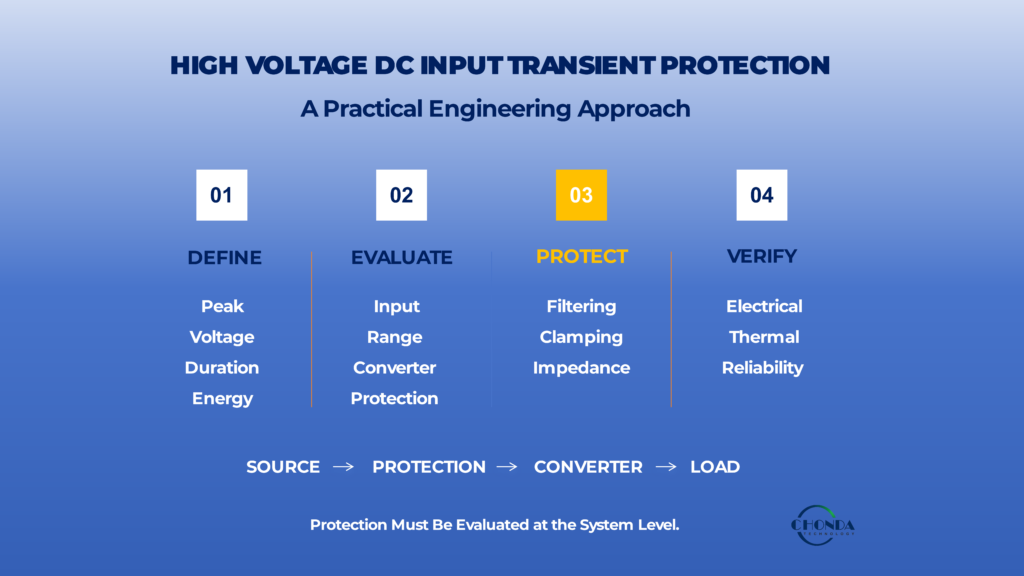
8.1 Start With the Normal Input-Voltage Range
The first step is to define the converter’s normal operating input range.
This should include:
- minimum operating voltage
- nominal operating voltage
- maximum continuous voltage
- expected operating variation
The converter’s specified input range should cover these conditions with appropriate design margin.
For example, if a system normally operates across a wide DC-bus range, the converter should be selected based on the complete normal operating range, rather than the nominal bus voltage alone.
However, this is only the starting point.
8.2 Define the Actual Transient Environment
The next step is to identify the transient conditions that may appear at the converter input.
Where possible, engineers should determine:
- peak transient voltage
- minimum transient voltage
- rise and fall time
- pulse duration
- waveform
- source impedance
- available transient energy
- expected repetition rate
This information is more useful than simply stating that the system has “high voltage transients.”
A converter can only be evaluated properly when the electrical disturbance itself has been defined.
Do not select the converter first and investigate the transient later.
The transient environment should be understood early in the selection process.
8.3 Check the Converter’s Input Protection Capability
Once the transient environment is known, review the converter manufacturer’s specifications for input protection and abnormal-input behavior.
Relevant information may include:
- input overvoltage protection
- transient withstand capability
- input protection structure
- protection thresholds
- shutdown behavior
- restart behavior
- recommended external protection
The key question is not simply:
“Does this converter have overvoltage protection?”
Instead, ask:
“Is the converter’s protection capability appropriate for the transient conditions in this application?”
This distinction prevents a common mistake: treating the existence of a protection function as proof of adequate transient immunity.
8.4 Compare the Transient With Component and System Limits
The transient should then be compared with the electrical limits of the converter and its surrounding protection network.
The evaluation should consider:
Transient voltage
→ Protection response
→ Voltage reaching converter
→ Stress on internal components
The final voltage experienced by the converter may be significantly different from the original source transient if an appropriately designed protection network is present.
This is why converter selection and protection design should be considered together.
8.5 Consider the Converter’s Input Architecture
The converter’s architecture should also be reviewed.
Important questions include:
- How is the high voltage input handled internally?
- Is the input stage designed for the expected voltage range?
- How is transient energy controlled?
- What protection functions are integrated?
- How does the converter behave during input overvoltage?
- Does the design allow external protection to be added easily?
For demanding high voltage applications, these questions can be more informative than comparing nominal input specifications alone.
8.6 Check Thermal Conditions During Transient Events
The converter and its protection network should also be evaluated under the expected thermal conditions.
Consider:
- ambient temperature
- converter operating power
- enclosure conditions
- cooling method
- transient repetition rate
- additional losses from protection components
A transient event may be acceptable under normal laboratory temperature but more demanding when the converter is already operating near its maximum temperature or power level.
Therefore, the selection process should consider a realistic electrical + thermal operating envelope.
8.7 Evaluate Startup and Switching Conditions
Startup should be included in the assessment.
Engineers should consider whether the converter may experience abnormal input conditions when:
- a high voltage DC bus is connected
- contactors close
- input capacitors charge
- upstream converters start
- multiple loads are connected simultaneously
A converter that performs correctly during steady-state operation may still require additional consideration during startup.
Similarly, repeated switching events during normal system operation should be considered when defining the transient environment.
8.8 Determine Whether External Protection Is Required
After reviewing the converter’s capabilities, determine whether the application can be handled by the converter alone or whether external protection is required.
A practical decision process is:
Transient within converter capability?
→ Yes: Use the converter within its specified conditions.
→ No / Uncertain: Evaluate additional external protection.
External protection may also be appropriate when the transient energy is significant or when the system environment is not sufficiently controlled.
The important principle is:
External protection should be based on a defined transient requirement, not added simply because the input voltage is high.
8.9 Verify the Complete System, Not Just the Converter
Before finalizing the selection, evaluate the complete electrical path:
Power Source → Wiring → Protection Network → High Voltage DC-DC Converter → Load
This is particularly important because cable inductance, source impedance, protection-device location, and load behavior can all influence the actual waveform seen at the converter input.
A converter that appears suitable from its datasheet may require additional system-level evaluation before it can be considered suitable for the final equipment.
8.10 A Practical Selection Checklist
The following checklist can be used during converter selection:
| Selection Item | Key Question |
|---|---|
| Normal input range | Does the converter cover the complete continuous operating range? |
| Transient voltage | What is the maximum expected transient voltage? |
| Transient duration | How long does the disturbance last? |
| Transient energy | How much energy is available during the event? |
| Repetition | How frequently can the event occur? |
| Internal protection | What input protection is integrated into the converter? |
| External protection | Is additional suppression or filtering required? |
| Thermal conditions | Can the protection system operate reliably at the actual temperature? |
| Startup behavior | Are startup and bus-connection events included? |
| System architecture | Has the complete source-to-converter path been evaluated? |
| Reliability margin | Is sufficient margin available for tolerance, aging, and operating variation? |
The goal is not simply to find a converter with the highest possible input-voltage rating.
The better approach is to select a converter whose normal operating range, transient capability, input architecture, protection strategy, thermal behavior, and reliability margin match the actual requirements of the application.
A high voltage DC-DC converter should be selected for the electrical environment it will actually experience—not simply for the voltage printed on the system specification.
This provides the basis for the final section, where we can summarize the most common mistakes engineers make when evaluating high voltage DC input transients and turn them into a practical design checklist.
9. Common Design Mistakes and Final Checklist
Input transient problems are often not caused by a single incorrect component selection. More commonly, they result from treating the transient environment as a secondary issue after the converter has already been selected.
A more reliable approach is to evaluate the transient conditions together with the converter, input network, thermal environment, and overall system architecture.
9.1 Treating the Maximum Input Voltage as the Transient Rating
One of the most common mistakes is assuming that the converter’s maximum input voltage is also its transient withstand level.
For example, a converter specified for a maximum continuous input voltage does not automatically mean that a significantly higher short-duration voltage spike can be applied repeatedly without additional protection.
The following specifications should be considered separately:
Normal operating voltage
Maximum continuous input voltage
Transient withstand capability
Protection threshold
These values may be related, but they do not represent the same operating condition.
9.2 Evaluating Only the Peak Voltage
Another common mistake is focusing only on the highest voltage reached during the transient.
Peak voltage is important, but it does not fully describe the event.
Engineers should also consider:
- duration
- rise time
- source impedance
- current
- energy
- repetition rate
- waveform
A short, low-energy spike and a longer, high-energy disturbance may have the same peak voltage while creating very different levels of stress.
Therefore:
Transient assessment should be based on the complete event, not a single voltage number.
9.3 Assuming an Input Filter Solves Every Transient Problem
Input filtering can reduce certain disturbances, but it should not automatically be considered complete transient protection.
The filter itself can experience electrical and thermal stress when exposed to abnormal input conditions.
In addition, the effectiveness of a filter depends on its topology, component values, damping, layout, and connection to the source and converter.
A filter should therefore be evaluated according to the actual transient waveform rather than simply added as a general-purpose solution.
9.4 Assuming Internal Protection Is Sufficient
A converter may include input overvoltage protection or other protective functions.
However, internal protection is generally designed according to specific operating and fault assumptions.
If the external system can generate transient conditions beyond those assumptions, additional system-level protection may still be necessary.
The correct question is therefore not:
“Does the converter have protection?”
but:
“Does the converter’s protection capability match the actual transient environment?”
9.5 Ignoring Source Impedance and Wiring
A transient cannot be understood correctly without considering where it comes from and how it reaches the converter.
Cable length, bus structure, source impedance, connectors, and PCB layout can all influence the actual waveform at the converter input.
A protection device located too far from the converter may also provide less effective protection than expected during a very fast transient.
Therefore, transient analysis should include the complete electrical path from source to converter.
9.6 Ignoring Repeated Events
A protection solution may survive a single test pulse while performing poorly under repeated events.
Repeated switching, regenerative operation, startup cycles, or other recurring disturbances can create cumulative electrical and thermal stress.
Engineers should therefore ask:
How often can this transient occur during the expected service life of the equipment?
This question is particularly important when protection components are expected to absorb significant transient energy.
9.7 Ignoring Temperature
Transient protection and thermal design are closely connected.
A system operating at elevated ambient temperature, high load, or limited airflow may have less available design margin than the same system under laboratory conditions.
The protection network should therefore be evaluated under realistic worst-case thermal conditions rather than only at room temperature.
9.8 Adding Protection Without Considering Normal Operation
More protection components do not automatically mean a better design.
Additional components can introduce:
- voltage drop
- power loss
- additional heat
- parasitic impedance
- increased physical size
- additional failure points
The protection network should therefore be designed so that it has minimal impact on normal operation while effectively limiting abnormal transient stress.
9.9 A Final Practical Checklist
Before approving a high voltage DC-DC converter for an application with input transients, engineers can review the following questions:
| Check | Question |
|---|---|
| Normal input range | Is the complete continuous input range clearly defined? |
| Transient source | Do we know where the transient originates? |
| Peak voltage | What is the maximum expected transient voltage? |
| Duration | How long does the transient last? |
| Rise time | How quickly does the voltage change? |
| Energy | How much energy is associated with the event? |
| Repetition | How frequently can the event occur? |
| Source impedance | What electrical impedance does the transient source present? |
| Converter capability | What transient conditions can the converter tolerate? |
| Internal protection | What protection is already integrated? |
| External protection | Is additional filtering, clamping, or impedance required? |
| Layout | Can the protection network effectively control the voltage at the converter input terminals? |
| Thermal conditions | Can the system handle the associated heat under worst-case conditions? |
| Startup | Have startup and DC-bus connection events been evaluated? |
| Reliability | Is sufficient margin available for aging and repeated transient exposure? |
9.10 The Key Engineering Principle
Input transient protection should ultimately be treated as part of the complete high voltage DC power architecture.
A suitable design connects four areas:
Transient Environment
→ Protection Network
→ Converter Architecture
→ Thermal and Reliability Performance
The objective is not simply to prevent one voltage spike from damaging one component.
The real objective is to ensure that the high voltage DC-DC converter can operate reliably within the electrical environment that the complete system will actually create.
A robust transient-protection strategy begins with understanding the disturbance, limits the stress reaching the converter, and maintains sufficient electrical and thermal margin throughout the intended service life.
CHONDA Connection
For high voltage DC-DC converter applications, transient conditions should be evaluated together with the required input range, isolation, efficiency, thermal performance, protection strategy, and mechanical integration.
CHONDA provides high voltage DC-DC power modules for applications requiring wide DC input ranges and isolated low-voltage outputs, with OEM/custom design support available when the electrical environment or mechanical requirements cannot be fully addressed by a standard module.
For application-specific projects, engineers should provide the expected:
Input Voltage Range + Transient Conditions + Output Requirement + Power + Isolation + Environmental Conditions
This allows the converter architecture and protection approach to be evaluated against the actual system requirements rather than only the nominal voltage specification.
Conclusion
Input transients are an important consideration when selecting and designing high voltage DC-DC conversion systems.
A wide input-voltage range defines the converter’s normal operating envelope, but it does not by itself define transient withstand capability. Engineers should identify the source, magnitude, duration, energy, and repetition of expected transient events before deciding whether the converter’s internal protection is sufficient or additional external protection is required.
The most reliable approach is to evaluate the transient environment, protection network, converter architecture, thermal conditions, and long-term reliability together.
This system-level approach helps prevent both immediate electrical overstress and gradual degradation caused by repeated transient exposure.
Related Articles
- How to Select a High Voltage DC-DC Converter Module for Industrial Applications
- High Voltage DC-DC Converter Isolation Design: Principles and Applications
- High Voltage DC-DC Converter Protection Features
- How to Improve High Voltage DC-DC Converter Reliability