We help the world since 2012

High Voltage DC-DC Converter Power Rating: How to Size a Converter for Industrial Applications
Selecting the correct power rating is one of the most important steps when choosing a high-voltage DC-DC converter for an industrial application.
A converter that is too small may operate close to its limits, resulting in excessive thermal stress, reduced efficiency, protection triggering, or unreliable operation under peak loads.
A converter that is significantly oversized may provide additional capacity, but it can also increase system cost, physical size, idle losses, and integration requirements without providing a meaningful benefit.
For this reason, converter power should not be selected simply by looking at the nominal load current.
Engineers should consider the complete load profile, including:
- Continuous operating power
- Peak power
- Startup conditions
- Transient loads
- Duty cycle
- Input-voltage range
- Converter efficiency
- Ambient temperature
- Cooling conditions
- Required design margin
The correct power rating is therefore the result of matching the converter to the actual electrical and thermal requirements of the system.
This is particularly important when evaluating a high voltage DC-DC converter module for industrial applications, including PV monitoring, battery energy storage systems, industrial automation, robotics, and embedded power systems.
This guide explains how engineers can evaluate these factors and select an appropriate power rating for a high-voltage DC-DC converter without unnecessarily oversizing or undersizing the power stage.
1. Start with the Actual Load Power
The first step in sizing a high-voltage DC-DC converter is to determine how much power the downstream load actually requires.
The converter power rating should be based on the real operating conditions of the equipment rather than on the input-bus voltage alone.
A basic starting point is:
Output Power = Output Voltage × Output Current
For example, a 24VDC load operating at 2A requires approximately 48W of output power under that operating condition.
However, the nominal or average load is not always sufficient for selecting the converter rating.
Engineers should identify at least three different power conditions:
1.1 Continuous Operating Power
Continuous operating power is the power the downstream load requires during normal operation.
For example, a monitoring unit may normally consume 20W continuously even though its electronics occasionally require additional power during communication or measurement events.
The continuous power level is important because it determines the thermal load that the converter must handle for long periods.
1.2 Peak or Transient Power
Some loads require more power for a short period of time.
Examples may include:
- Communication bursts
- Motor or actuator startup
- Relay or solenoid activation
- Sensor excitation
- Processing or measurement events
- Temporary increases in control-system demand
A converter that is suitable for the continuous load may still be unsuitable if it cannot handle the required peak condition.
The duration and frequency of these peaks should therefore be considered, rather than treating every short-duration event as continuous power.
1.3 Startup Power
Startup conditions can be different from normal operating conditions.
During startup, the power supply may need to charge capacitors, initialize electronics, or supply loads that have not yet reached their normal operating state.
Engineers should therefore consider:
Startup → Normal Operation → Peak Load → Return to Normal Operation
This sequence can be more representative of the real converter requirement than a single steady-state power value.
1.4 Build a Load Profile
For a more accurate sizing decision, the load can be divided into operating states.
For example:
| Operating Condition | Output Power | Duration |
|---|---|---|
| Standby | 10W | Continuous |
| Normal operation | 30W | Continuous |
| Communication event | 45W | 10 s |
| Peak measurement | 60W | 2 s |
This type of load profile helps engineers determine whether the converter should be selected based on continuous power, short-term peak capability, or a combination of both.
A converter should not automatically be selected at 60W simply because a 60W event occurs for two seconds. The converter’s specified overload capability, thermal conditions, protection behavior, and peak-power duration must also be considered.
1.5 Consider the Complete Downstream Load
The calculated output power should include all loads supplied by the converter.
For example, an industrial monitoring supply may power:
- Main controller
- Sensors
- Communication interface
- Measurement circuits
- Auxiliary relays
- Cooling or interface devices
Ignoring smaller auxiliary loads can lead to an underestimated total power requirement.
The initial sizing process should therefore start with a complete load list before selecting a converter.
Once the continuous, peak, startup, and auxiliary loads have been identified, engineers can move to the next step: accounting for converter efficiency and determining the required input power and design margin.
2. Account for Converter Efficiency
Once the actual output load has been identified, the next step is to consider converter efficiency.
A high-voltage DC-DC converter does not transfer 100% of the input power to the output. Some energy is lost through switching devices, magnetic components, rectification, conduction resistance, control circuits, and other parts of the power stage.
A simple relationship is:
Input Power = Output Power / Efficiency
For example, if the load requires 100W and the converter operates at 90% efficiency:
Input Power = 100W / 0.90 ≈ 111W
The difference between input and output power is converted primarily into heat within the converter.
2.1 Why Efficiency Matters for Power Sizing
Efficiency is important not only for energy consumption but also for thermal design.
A lower-efficiency converter must process more input power to deliver the same output power, which increases the amount of heat that must be removed.
For example:
| Output Power | Efficiency | Approx. Input Power | Approx. Power Loss |
|---|---|---|---|
| 50W | 90% | 55.6W | 5.6W |
| 100W | 90% | 111.1W | 11.1W |
| 100W | 95% | 105.3W | 5.3W |
| 200W | 95% | 210.5W | 10.5W |
Even a relatively small difference in efficiency can become important as output power increases.
2.2 Efficiency Changes with Operating Conditions
Converter efficiency is not necessarily constant across the entire operating range.
It may vary with:
- Input voltage
- Output voltage
- Output current
- Load level
- Switching frequency
- Ambient temperature
A converter that achieves a high peak-efficiency figure at one operating point may have lower efficiency at light load or under different input conditions.
For this reason, engineers should evaluate efficiency at the actual expected operating points, rather than relying only on the maximum efficiency stated in a specification.
2.3 Light Load and Typical Load Conditions
The converter’s normal operating point is particularly important.
If a converter is rated for 200W but the application normally operates at only 30W, the peak efficiency at 200W may be less relevant than the efficiency around the 30W operating region.
The expected load profile should therefore be considered together with the converter’s efficiency curve.
This is especially relevant for monitoring and embedded systems that may spend long periods at relatively low power while occasionally experiencing short-duration peaks.
2.4 Efficiency and Thermal Design Are Connected
The power that is not delivered to the load becomes converter loss.
A simplified relationship is:
Power Loss = Input Power − Output Power
This loss contributes to temperature rise within components such as:
- Power semiconductors
- Transformers
- Inductors
- Rectifiers
- Capacitors
- PCB conductors
As the converter power rating increases, the thermal consequences of these losses become more significant.
A converter should therefore be evaluated not only for whether it can deliver the required output power, but also for whether it can dissipate the associated losses under the intended operating conditions.
2.5 Use Real Operating Efficiency for Sizing
For practical power sizing, engineers should use a realistic efficiency value based on the expected operating condition.
A useful sequence is:
Load Power → Expected Efficiency → Input Power → Power Loss → Thermal Requirement
This provides a more realistic foundation for selecting the converter and evaluating the required thermal margin.
Once the expected load power and efficiency have been established, the next step is to determine how much additional power margin is appropriate for normal variation, peak conditions, production tolerance, and future load changes.
3. Add Appropriate Design Margin
Once the required output power and expected converter efficiency have been established, engineers should determine how much additional power margin is appropriate.
Selecting a converter with exactly the calculated load power may leave insufficient capacity for normal variation, transient events, temperature changes, production tolerances, or future load increases.
However, selecting an unnecessarily large converter can also increase cost, physical size, and no-load or light-load losses.
The objective is therefore to choose a reasonable design margin, not simply the largest available power rating.
3.1 Why Design Margin Is Needed
Actual operating conditions are rarely identical to the initial design estimate.
The load may vary because of:
- Component tolerances
- Different operating modes
- Communication activity
- Sensor operation
- Startup conditions
- Future system expansion
- Production variation
A suitable margin gives the power supply additional capacity to handle these expected variations without operating continuously at its maximum rating.
3.2 Margin Should Be Based on the Load Profile
The appropriate margin depends on how the converter will actually be used.
For a stable load with very little variation, a relatively modest margin may be sufficient.
For a system with frequent load changes, uncertain future requirements, or significant startup and transient conditions, a greater margin may be appropriate.
For example, if the calculated continuous output requirement is 100W, an engineer might evaluate a 120W or 150W converter depending on:
- Peak-power requirements
- Operating temperature
- Cooling conditions
- Expected load growth
- Converter overload capability
- Reliability requirements
These values are examples rather than universal sizing rules. The appropriate margin must be determined from the actual application and converter specifications.
3.3 Continuous Rating and Peak Capability Are Different
Engineers should distinguish between:
Continuous Power Rating
and
Short-Term Peak Capability
A converter may be able to tolerate a temporary load above its continuous rating without being suitable for continuous operation at that level.
For example, a converter may continuously deliver 100W while supporting a short-duration 120W transient under specified conditions.
This does not mean that the converter should be treated as a 120W continuous power supply.
The specified overload duration, recovery behavior, thermal conditions, and protection strategy must be checked carefully.
3.4 Temperature Can Reduce Available Margin
The usable power capacity of a converter may also depend on ambient temperature and cooling conditions.
A module that can deliver its full rated power under favorable laboratory conditions may require derating at higher ambient temperatures or under restricted airflow.
Engineers should therefore evaluate:
- Ambient temperature
- Internal temperature rise
- Cooling method
- Enclosure conditions
- Required derating
Power margin should be considered together with thermal margin.
3.5 Avoid Both Undersizing and Excessive Oversizing
Undersizing can lead to:
- Continuous operation close to the maximum rating
- Excessive temperature rise
- Protection triggering
- Reduced reliability
- Insufficient transient capability
Excessive oversizing can lead to:
- Higher cost
- Larger physical dimensions
- Lower efficiency at light load
- Higher standby losses
- More difficult mechanical integration
The goal is to select a converter that has sufficient capacity without creating unnecessary system overhead.
3.6 A Practical Sizing Sequence
A practical approach can be summarized as:
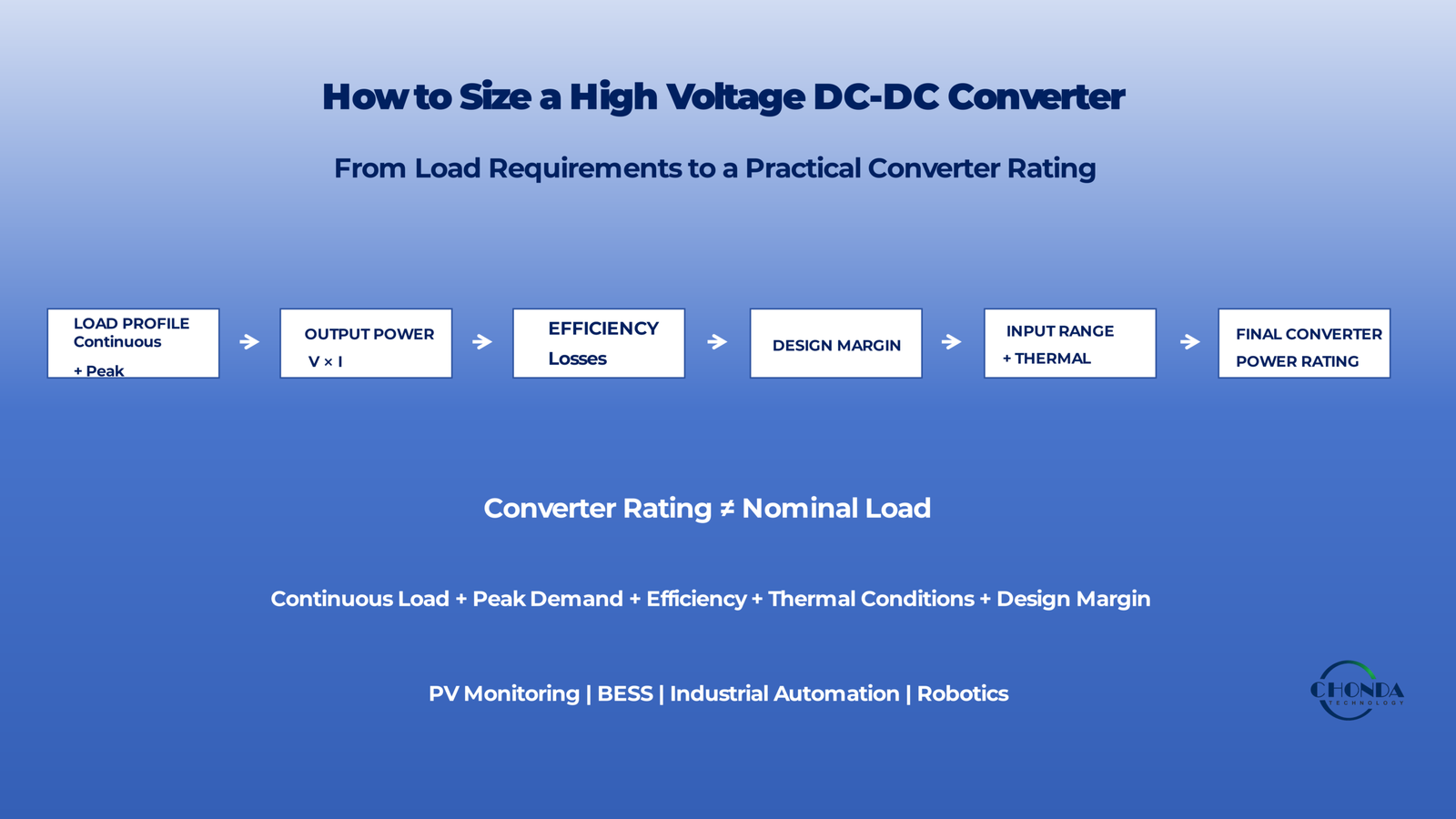
Continuous Load → Peak Load → Efficiency → Thermal Conditions → Design Margin → Converter Rating
For example, if a system requires 100W continuously, experiences occasional short-duration peaks, and operates in a controlled thermal environment, the engineer should evaluate the complete operating profile before selecting the next available converter rating.
The final rating should be based on the converter’s specified continuous capability, transient capability, thermal derating, and the actual requirements of the application.
3.7 Design Margin Is Application-Specific
There is no single percentage that is correct for every high-voltage DC-DC converter.
The appropriate margin depends on:
- Load stability
- Peak-power duration
- Input-voltage range
- Ambient temperature
- Cooling
- Converter topology
- Protection behavior
- Reliability requirements
- Expected future load
The best power rating is therefore the one that provides sufficient operating margin without unnecessary oversizing.
After establishing the required margin, engineers can evaluate whether the selected converter can maintain its rated output across the full input-voltage range and under the expected operating conditions.
4. Check the Full Input-Voltage Range
After determining the required output power and design margin, engineers should verify that the selected high-voltage DC-DC converter can deliver the required power across the complete input-voltage range.
A converter may be rated for a specific maximum power, but its actual operating capability can depend on the input voltage.
For high-voltage applications, the difference between minimum, nominal, and maximum input voltage can be significant.
4.1 Nominal Input Voltage Is Not Enough
A converter should not be sized only from the nominal DC-bus voltage.
For example, a system described as a 1000VDC application may operate over a defined range rather than at exactly 1000VDC.
The engineer should therefore identify:
- Minimum input voltage
- Nominal input voltage
- Maximum input voltage
- Startup conditions
- Input transients
The converter must be evaluated against the full specified operating range.
4.2 Input Voltage Affects Input Current
For a given output power, lower input voltage generally requires higher input current.
A simplified relationship is:
Input Current ≈ Input Power / Input Voltage
This means that a converter delivering the same output power may experience significantly higher input current when operating near the low end of its input-voltage range.
Higher input current can affect:
- Semiconductor stress
- Conduction losses
- Connector and wiring losses
- PCB copper requirements
- Thermal performance
- Protection thresholds
The low-input-voltage operating point can therefore become an important part of the converter sizing decision.
4.3 Check Rated Power Across the Operating Range
Engineers should verify how the manufacturer’s specified output-power capability changes across the input range.
Some converters may provide their full rated power across the complete specified range.
Others may require derating under certain input-voltage, temperature, or load conditions.
The relevant information may be provided through:
- Output-power curves
- Derating curves
- Efficiency curves
- Maximum-output-current specifications
- Thermal limits
These characteristics should be reviewed before assuming that the nominal power rating applies under every operating condition.
4.4 High-Voltage Input Does Not Automatically Mean Higher Available Power
A higher input voltage can reduce the current required for a given input power, but it does not automatically mean that the converter can deliver more output power.
The actual power capability is still limited by:
- Semiconductor ratings
- Transformer or magnetic design
- Thermal limits
- Control strategy
- PCB design
- Protection settings
The converter’s rated power should therefore always be taken from its specified operating conditions rather than inferred from the input voltage.
4.5 Consider Low-Voltage and High-Voltage Operating Extremes
Both ends of the input range can create different engineering challenges.
At the low-input-voltage end, the converter may require higher input current and experience greater conduction losses.
At the high-input-voltage end, the design may experience greater electrical stress on:
- Switching devices
- Transformer insulation
- Capacitors
- PCB spacing
- Other high-voltage components
The converter should therefore be checked at both operating extremes.
4.6 Input Range and Power Rating Must Be Evaluated Together
A practical sizing review should combine the key variables:
Input Range → Output Power → Input Current → Efficiency → Thermal Stress → Converter Rating
This helps engineers avoid selecting a converter based only on one nominal operating point.
For high-voltage industrial applications, the selected converter should be able to provide the required continuous and peak power under the complete expected input-voltage and environmental conditions.
Once the full input range has been verified, the next step is to evaluate how temperature and cooling conditions affect the converter’s available power capacity.
5. Check Thermal Conditions and Derating
A high-voltage DC-DC converter may be able to deliver its specified power under favorable conditions, but the available power can change when the ambient temperature, cooling method, or installation environment becomes more demanding.
For this reason, power sizing should always consider thermal conditions and any required derating.
A converter that is correctly sized from an electrical perspective may still be undersized from a thermal perspective.
5.1 Power Loss Becomes Heat
The difference between input power and output power represents power loss within the converter.
These losses may come from:
- Switching devices
- Transformer or magnetic components
- Rectification
- Conduction resistance
- Control circuits
- PCB and interconnections
As output power increases, the amount of heat generated by these losses also increases.
The converter must therefore be able to transfer this heat away from its internal components and maintain acceptable operating temperatures.
5.2 Ambient Temperature Affects Available Power
A converter operating at room temperature may be able to deliver its full rated power.
The same converter installed inside a hot enclosure, with limited airflow, may have a lower practical power capability.
Engineers should therefore consider:
- Minimum and maximum ambient temperature
- Internal enclosure temperature
- Natural or forced airflow
- Heat-sink arrangement
- PCB thermal paths
- Installation location
The actual operating temperature of the converter can be significantly higher than the surrounding ambient temperature.
5.3 Derating
Derating means operating a component or power supply below its maximum rated capability under more demanding conditions.
For example, a converter may provide its full rated power at a specified ambient temperature but require a lower power level at higher temperatures.
A simplified sizing process can therefore be thought of as:
Required Load Power → Design Margin → Thermal Conditions → Available Rated Power
The engineer should verify the manufacturer’s power-versus-temperature or derating information rather than assuming that the nominal power rating is available under every condition.
5.4 Enclosure and Cooling Conditions Matter
The converter should not be evaluated as if it were operating in free air unless that matches the real installation.
Thermal performance may change significantly when the module is installed:
- Inside a sealed enclosure
- Near other heat-generating components
- On a densely populated PCB
- In a high-temperature environment
- With restricted airflow
The surrounding system can therefore influence the practical power capability of the converter.
5.5 Temperature Can Affect Reliability
Operating continuously at elevated temperature can increase stress on components and may reduce long-term reliability.
High temperature can affect:
- Semiconductor lifetime
- Capacitor lifetime
- Transformer insulation
- Magnetic performance
- Solder joints
- Other temperature-sensitive components
For this reason, thermal margin should be considered together with electrical power margin.
A converter with sufficient nominal power but inadequate thermal margin may not be a reliable choice for continuous industrial operation.
5.6 Consider the Worst-Case Operating Condition
Power sizing should be verified under the most demanding realistic conditions rather than only at the easiest operating point.
A practical worst-case review may include:
Maximum Ambient Temperature + Maximum Expected Load + Minimum Cooling + Relevant Input Condition
If the converter can meet the required output power under this condition, the design has a stronger basis for reliable operation.
5.7 Thermal Derating and Converter Selection
Before selecting the final converter rating, engineers should review:
- Continuous output power
- Peak output capability
- Efficiency at the expected load
- Ambient temperature
- Cooling conditions
- Derating requirements
- Internal temperature limits
For a deeper discussion of thermal design, see High Voltage DC-DC Converter Thermal Management.
The key principle is simple:
The usable power rating is the power the converter can reliably deliver under the actual installation conditions, not simply the largest number printed on the datasheet.
6. Continuous Power vs. Peak Power Capability
When sizing a high-voltage DC-DC converter, engineers should distinguish between continuous output power and short-duration peak-power capability.
These two specifications describe different operating conditions and should not be treated as interchangeable.
A converter may be capable of supporting a temporary load above its continuous rating, but that does not necessarily mean it can operate continuously at that higher power level.
6.1 Continuous Power Rating
Continuous power is the output power that the converter is designed to deliver for sustained operation under its specified conditions.
This rating is particularly important for industrial equipment that operates for long periods without interruption.
Continuous power capability is influenced by factors such as:
- Semiconductor temperature
- Transformer or magnetic temperature
- Cooling conditions
- Ambient temperature
- PCB thermal paths
- Internal power losses
When selecting a converter, the expected continuous load should therefore remain within the specified continuous operating capability after accounting for the relevant thermal conditions and design margin.
6.2 Peak Power Capability
Some converters can temporarily support output power above their continuous rating.
Peak-power capability may be useful when the load experiences short-duration events such as:
- Motor startup
- Communication bursts
- Relay or actuator operation
- Capacitor charging
- Temporary measurement or processing events
However, peak capability is meaningful only when the converter specification clearly defines the permitted conditions.
Engineers should check:
- Maximum peak power
- Peak duration
- Allowed repetition rate
- Required recovery time
- Input-voltage conditions
- Ambient-temperature limitations
A converter that supports a short 120W peak from a 100W continuous rating should not automatically be treated as a 120W continuous converter.
6.3 Overload Capability Is Not the Same as Rated Power
A converter may enter a controlled overload or current-limiting mode when the load exceeds its normal operating range.
Depending on the design, this may involve:
- Current limiting
- Foldback
- Hiccup protection
- Thermal protection
- Controlled shutdown
These functions are intended to protect the converter under abnormal conditions.
They should not be used as a substitute for adequate continuous power capacity.
6.4 Startup Power Requires Special Attention
Startup can create a temporary demand that differs significantly from normal operation.
For example, the converter may need to charge downstream capacitors or bring multiple subsystems online at the same time.
The startup event may therefore require more power than the normal steady-state load.
Engineers should determine whether the selected converter can:
- Start reliably under the required load
- Meet the required startup sequence
- Handle inrush conditions
- Avoid unnecessary protection triggering
Startup capability should be evaluated separately from both continuous and short-duration peak-power capability.
6.5 Peak Power and Thermal Stress
Even when a short peak is electrically acceptable, repeated peak events can increase average power loss and thermal stress.
For example, a converter that experiences a 20% overload for only a few seconds may be suitable for an occasional event, but repeated peaks every few seconds may produce a very different thermal condition.
The frequency and duration of peak events should therefore be included in the load profile.
6.6 Read the Datasheet Carefully
Power ratings should always be interpreted together with the conditions under which they are specified.
Engineers should look for:
- Continuous power rating
- Peak-power specification
- Derating curves
- Overload duration
- Input-voltage limitations
- Ambient-temperature limits
- Cooling requirements
- Protection behavior
A single headline value such as “100W” does not provide enough information to determine whether a converter is suitable for every load condition.
6.7 A Practical Power-Rating Check
A useful review sequence is:
Continuous Load → Peak Load → Startup → Peak Duration → Duty Cycle → Thermal Conditions → Converter Rating
The selected converter should be able to support the required continuous power under the worst expected conditions while also providing any necessary peak capability within the manufacturer’s specified limits.
Understanding this distinction helps engineers avoid both undersizing the converter and paying for unnecessary oversizing.
7. Consider Input Current and Operating Conditions
When sizing a high-voltage DC-DC converter, engineers should consider not only the required output power but also the input current under the actual operating conditions.
For a given power level, the input current changes as the input voltage changes. This becomes particularly important in converters designed to operate across a wide high-voltage input range.
A converter that delivers the required output power at one nominal input voltage may experience substantially different electrical and thermal conditions at another point in the operating range.
7.1 Input Current Depends on Power and Voltage
A simplified relationship is:
Input Current ≈ Input Power / Input Voltage
Because input power is greater than output power due to conversion losses, the actual input current should be estimated using a realistic efficiency value.
For example, if a converter delivers 100W at 90% efficiency, the required input power is approximately 111W.
At a 1000V input, the average input current is relatively low.
At a 200V input, the same power level requires a much higher input current.
This difference can affect the design of:
- Switching devices
- Input capacitors
- PCB copper
- Connectors
- Wiring
- Protection components
- Thermal paths
7.2 Low Input Voltage Can Become a Limiting Condition
For a converter with a wide input-voltage range, the lowest operating voltage may create one of the most demanding conditions from a current and thermal perspective.
As input voltage decreases while output power remains similar, input current increases.
Higher input current can increase:
- Conduction losses
- Component temperature
- PCB voltage drop
- Connector losses
- Stress on input protection devices
The converter should therefore be checked at the low end of the input range rather than being evaluated only at the nominal or maximum input voltage.
7.3 High Input Voltage Creates Different Electrical Stress
The high end of the input range creates a different set of challenges.
Higher input voltage can increase electrical stress on:
- Power semiconductors
- Input capacitors
- Transformer insulation
- PCB insulation structures
- Switching nodes
- Protection components
This means that the minimum and maximum input-voltage conditions can represent very different worst-case scenarios.
A practical sizing review should therefore evaluate both ends of the operating range.
7.4 Input Current and Thermal Design
Input current also affects the amount of heat generated through resistive losses.
For example, conductor and semiconductor conduction losses are generally sensitive to current. As current increases, associated losses can increase significantly.
This is particularly important for:
- Low-input-voltage operation
- High-output-power operation
- High ambient temperature
- Compact converter designs
- Restricted cooling environments
Input-current analysis should therefore be considered together with the thermal design rather than as a purely electrical calculation.
7.5 Input Source Capability
The DC source itself must also be capable of supplying the required input power.
Engineers should verify:
- Available source power
- Maximum source current
- Source impedance
- Wiring losses
- Upstream protection
- Voltage droop under load
- Transient response
A converter may have sufficient output-power capability while the upstream DC source is unable to provide the required input current under worst-case conditions.
This can lead to unexpected input-voltage drop, converter shutdown, or unstable startup behavior.
7.6 Wide-Input Converters Require More Than a Wide Specification
A converter marketed for a wide input range should not be evaluated only from the stated minimum and maximum voltage.
Engineers should also verify whether the converter can provide the required power across that entire range and under the actual thermal conditions.
Important questions include:
- Is the full rated power available across the whole input range?
- Does the efficiency change significantly with input voltage?
- Is output power derated at low input voltage?
- Are there input-current limitations?
- Are special startup conditions specified?
These details can be more important than the headline input-voltage range itself.
7.7 A Complete Input-Side Review
A practical review can be summarized as:
Output Power → Efficiency → Input Power → Input Voltage → Input Current → Source Capability → Thermal Stress
This sequence helps engineers determine whether the selected high-voltage DC-DC converter is suitable not only at its nominal operating point but across the actual system operating range.
The input side should therefore be considered part of the converter-sizing problem rather than as a separate upstream issue.
8. Evaluate the Real Load Profile
Selecting a high-voltage DC-DC converter based on a single power value can be misleading when the downstream equipment operates under different load conditions.
Industrial and embedded systems rarely consume exactly the same amount of power at all times. The converter may operate in standby, normal operation, peak load, communication events, startup, or other application-specific modes.
For this reason, the real load profile should be considered before the final converter power rating is selected.
8.1 Identify the Main Operating Modes
Engineers should first identify how the equipment actually operates.
Typical operating modes may include:
- Standby
- Normal operation
- Measurement or sensing
- Communication
- Actuation
- Startup
- Fault or recovery conditions
Each mode may have a different power requirement.
8.2 Calculate the Typical Operating Point
The typical operating point is often more important than the absolute peak if the system spends most of its operating time under normal load.
For example, a monitoring unit may operate at 30W for most of the day but occasionally increase to 50W during communication or measurement activity.
In this case, the converter’s efficiency and thermal behavior at approximately 30W may be more relevant to long-term operation than its performance at the short-duration 50W peak.
8.3 Consider Duty Cycle
The duration and frequency of different load conditions should also be considered.
A short 60W event that occurs once every hour places very different demands on a converter than a 60W event that occurs every few seconds.
Engineers should therefore consider:
- Peak duration
- Peak frequency
- Duty cycle
- Time spent at normal load
- Time spent at low load
This information helps determine whether a temporary peak should be treated as a transient condition or as part of the converter’s effective continuous operating requirement.
8.4 Light-Load Operation Matters
Some systems spend significant periods operating well below their maximum load.
This can occur in:
- Monitoring equipment
- Communication systems
- Embedded controllers
- Battery-powered systems
- Industrial standby equipment
For these applications, light-load efficiency and regulation behavior may be important.
Selecting a converter based only on full-load efficiency can therefore produce an inaccurate picture of the system’s actual energy consumption and thermal behavior.
8.5 Multiple Loads May Operate at Different Times
A power supply may serve several loads that do not all reach their maximum power simultaneously.
For example, a monitoring system could contain:
- Control electronics
- Sensors
- Communication circuits
- Relay or interface devices
If all of these loads are assumed to operate at their individual maximum values simultaneously, the calculated power requirement may become unnecessarily conservative.
On the other hand, if the system can actually enter a mode where several loads operate together, that combined condition must be included in the sizing analysis.
The important question is therefore:
What is the worst realistic combination of loads?
8.6 Build a Practical Load Profile
A useful sizing table may look like:
| Operating Mode | Output Power | Duration | Frequency |
|---|---|---|---|
| Standby | 10W | Continuous | Continuous |
| Normal operation | 30W | Continuous | Continuous |
| Communication | 45W | 10s | Every 5 min |
| Measurement peak | 60W | 2s | Several times per hour |
This profile provides a more realistic basis for evaluating:
- Continuous power
- Peak power
- Efficiency
- Thermal behavior
- Required design margin
8.7 Avoid Designing for an Unrealistic Maximum
The highest theoretical load is not always the correct basis for sizing.
If a load condition can never occur during normal operation, using it as the continuous power requirement may unnecessarily increase converter size and cost.
Conversely, ignoring a realistic combination of loads can result in an undersized converter.
A good sizing process should therefore use the worst realistic operating condition, not simply the largest number found in an individual component datasheet.
8.8 Load Profile and Converter Selection
Once the load profile has been established, it can be used together with the previous sizing steps:
Load Profile → Continuous Power → Peak Power → Efficiency → Thermal Conditions → Design Margin → Converter Rating
This approach provides a more realistic basis for selecting a high-voltage DC-DC converter than relying on a single nominal load value.
For industrial applications, understanding how the equipment actually consumes power is often just as important as knowing its maximum rated power.
9. Determine the Final Converter Power Rating
After evaluating the load profile, efficiency, input-voltage range, thermal conditions, peak capability, and design margin, engineers can determine the required power rating of the high-voltage DC-DC converter.
Engineers selecting a high voltage DC-DC power module should compare the calculated power requirement with the module’s continuous rating, peak capability, input range, efficiency, and thermal derating.
The final selection should be based on the worst realistic operating condition rather than on a single nominal load value.
9.1 Start with Continuous Output Power
The continuous load remains the primary reference point for converter sizing.
For example, if the equipment requires 100W continuously, the selected converter should be capable of delivering at least the required continuous output under the expected input-voltage, ambient-temperature, and cooling conditions.
The continuous rating should be evaluated together with any applicable derating requirements.
9.2 Add the Required Design Margin
Once the continuous requirement has been established, an appropriate design margin can be added.
For example:
Required Continuous Power × Design Margin Factor
If a system requires 100W continuously and the engineering analysis determines that a 20% margin is appropriate, the resulting target is approximately 120W.
This does not mean that 20% is a universal recommendation. The appropriate margin depends on the load profile, thermal conditions, reliability requirements, peak behavior, and converter specifications.
9.3 Verify Peak-Power Requirements Separately
The final converter rating should also be checked against any short-duration peak demand.
For example, a system might require:
- 100W continuous
- 120W for a short communication event
- 60W during standby
In this case, the engineer should verify whether the selected converter can provide the required 120W peak under the specified duration and repetition conditions.
A converter that meets the continuous requirement but cannot tolerate the required peak may not be suitable.
9.4 Check the Rating Under Worst-Case Thermal Conditions
The selected power rating should remain valid under the actual installation conditions.
A converter with a nominal 150W rating may not be able to deliver 150W continuously if the manufacturer specifies derating at the system’s actual ambient temperature.
The engineer should therefore verify:
- Continuous output capability
- Peak capability
- Ambient-temperature limits
- Cooling conditions
- Derating curves
- Efficiency at the intended operating point
The usable rating is the capability available under the real operating conditions.
9.5 Select the Nearest Practical Rating
Once the required continuous power, peak demand, and thermal conditions have been established, the engineer can compare the result with available converter ratings.
For example:
Calculated requirement: 118W
Possible standard ratings:
- 100W
- 120W
- 150W
A 100W converter would be undersized.
A 120W converter may be appropriate if it meets the continuous, peak, thermal, and input-range requirements.
A 150W converter may provide additional margin but could increase cost, size, or light-load losses without providing a meaningful system benefit.
The correct choice therefore depends on the complete application rather than simply selecting the next-largest rating.
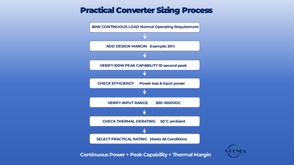
9.6 Example of a Complete Sizing Process
Consider an industrial monitoring system with the following requirements:
- Continuous output power: 80W
- Short-duration peak power: 100W
- Minimum input voltage: 300VDC
- Maximum input voltage: 800VDC
- Expected efficiency: 92%
- Elevated ambient temperature: 50°C
A practical sizing sequence would be:
80W continuous load
↓
Add appropriate design margin
↓
Verify 100W peak capability
↓
Check efficiency and resulting power losses
↓
Verify operation across 300–800VDC
↓
Check thermal derating at 50°C
↓
Select an available converter rating that satisfies all conditions
The important point is that the final rating cannot be determined from the 80W continuous load alone.
9.7 Do Not Select by Power Rating Alone
The final converter should also satisfy the complete electrical and system requirements.
Before approving the selection, engineers should verify:
- Input voltage range
- Output voltage and current
- Continuous power
- Peak capability
- Efficiency
- Thermal performance
- Isolation requirements
- Regulation
- Protection
- EMI
- Mechanical integration
Power rating is therefore one of the most important selection parameters, but it is not the only one.
9.8 Final Sizing Principle
A practical high-voltage DC-DC converter sizing process can be summarized as:
Load Profile → Continuous Power → Peak Power → Efficiency → Input Range → Thermal Conditions → Design Margin → Converter Rating
The final converter should provide sufficient capacity for the required continuous and transient conditions while maintaining appropriate electrical, thermal, and reliability margin.
The objective is not to maximize the converter power rating.
The objective is to select the smallest practical power rating that safely and reliably satisfies the complete application requirements.
10. A Practical High-Voltage DC-DC Converter Sizing Example
The following example illustrates how an engineer can estimate the required power rating of a high-voltage DC-DC converter for an industrial monitoring application.
Consider a monitoring unit supplied from a high-voltage DC bus with the following requirements:
- Input voltage: 300–1000VDC
- Output voltage: 24VDC
- Continuous load current: 3A
- Short-duration peak current: 4A
- Peak duration: 10 seconds
- Expected converter efficiency: 92%
- Maximum ambient temperature: 50°C
The objective is to determine a practical converter power rating rather than simply selecting a module based on the nominal 3A load.
10.1 Calculate the Continuous Output Power
The continuous output requirement is:
P = V × I
With a 24V output and 3A continuous load:
Pcontinuous = 24V × 3A = 72W
The monitoring system therefore requires approximately 72W of continuous output power.
10.2 Check the Peak Output Power
The short-duration peak current is 4A.
Therefore:
Ppeak = 24V × 4A = 96W
The converter must therefore be capable of supporting approximately 96W for the specified 10-second peak period, assuming the converter’s datasheet allows this operating condition.
A 72W continuous rating alone would not be sufficient unless the converter also provides the required peak capability.
10.3 Account for Converter Efficiency
Assuming an efficiency of 92%, the approximate input power during continuous operation is:
Pin = 72W / 0.92 ≈ 78.3W
During the 96W peak:
Pin,peak = 96W / 0.92 ≈ 104.3W
These values show that the converter must process more than the output load power because part of the input energy is lost inside the power stage.
The approximate continuous power loss is:
Ploss = 78.3W − 72W ≈ 6.3W
At the peak condition:
Ploss,peak = 104.3W − 96W ≈ 8.3W
These losses must be considered in the thermal design.
10.4 Add an Appropriate Design Margin
Assume that the engineering review determines that an approximately 20% continuous-power margin is appropriate for this application.
The continuous target becomes:
72W × 1.20 = 86.4W
A standard converter rating above this value would therefore be required for continuous operation.
However, the engineer must still verify that the selected converter can support the 96W peak for the required duration.
10.5 Check the Input-Voltage Range
The converter is required to operate from 300VDC to 1000VDC.
At the low end of the input range, the converter requires higher input current.
Using the continuous input-power estimate:
Iin,300V ≈ 78.3W / 300V ≈ 0.26A
At the 1000V input condition:
Iin,1000V ≈ 78.3W / 1000V ≈ 0.078A
The lower input-voltage condition therefore creates the higher input-current requirement.
This condition should be checked carefully against the converter’s current capability, conduction losses, thermal behavior, and any low-input-voltage derating.
10.6 Check the Thermal Condition
The application operates at an ambient temperature of 50°C.
The engineer should now verify the selected converter’s:
- Rated power at 50°C
- Derating curve
- Cooling requirements
- Maximum internal temperature
- Installation conditions
For example, a nominal 100W converter may not necessarily be capable of delivering 100W continuously at 50°C without additional cooling or derating.
The actual available power must therefore come from the converter’s specified thermal operating conditions.
10.7 Select a Practical Converter Rating
The basic requirements are now:
- 72W continuous output
- 96W short-duration peak
- Approximately 20% continuous design margin
- 300–1000VDC input
- 24VDC output
- Operation at 50°C ambient
A converter rated at 80W would not provide the requested continuous design margin.
A converter around 100W may be a reasonable candidate if its datasheet confirms:
- Continuous operation at the required temperature
- Required peak capability
- Full operation across the input range
- Required 24V output regulation
- Suitable isolation and protection
A 150W converter might provide additional margin, but its larger size, cost, and light-load operating characteristics should also be considered.
The final selection should therefore be based on the complete specification rather than on the headline wattage alone.
10.8 What This Example Demonstrates
This example shows why converter sizing should follow a structured process:
Load → Peak → Efficiency → Margin → Input Range → Thermal → Final Rating
The result is not simply:
72W load = 72W converter
Instead, the engineer needs to determine whether the selected converter can reliably support the continuous load, transient peak, temperature, input-voltage range, and required design margin under the actual installation conditions.
For a real product selection, the final decision should always be verified against the manufacturer’s detailed electrical, thermal, isolation, and protection specifications.
11. Verify the Converter Before Final Selection
Calculating the required power rating is only the first part of selecting a high-voltage DC-DC converter.
Before finalizing the design, engineers should verify that the selected converter can actually provide the required performance across the complete operating range.
A converter that appears suitable based on its nominal power rating may still be unsuitable when input-voltage limits, thermal conditions, peak-load behavior, isolation, or protection requirements are considered.
11.1 Verify the Electrical Specifications
The first step is to compare the application requirements with the converter’s specified operating conditions.
Engineers should confirm:
- Minimum and maximum input voltage
- Nominal input voltage
- Output voltage
- Continuous output current
- Continuous output power
- Peak-power capability
- Efficiency
- Output regulation
- Output ripple
The selected converter should meet the requirements without relying on unspecified or unsupported operating conditions.
11.2 Check Power and Temperature Together
The converter’s power rating should always be evaluated together with the expected temperature.
Review:
- Rated power at the actual ambient temperature
- Derating curves
- Cooling requirements
- Expected temperature rise
- Installation conditions
- Continuous-load behavior
A converter that meets the required power at room temperature may not provide the same capability inside a high-temperature enclosure.
11.3 Verify the Full Input Range
The converter should be checked at:
- Minimum input voltage
- Nominal input voltage
- Maximum input voltage
The engineer should confirm that the required continuous and peak power are available across the complete input range.
This is particularly important for wide-input high-voltage converters because the low-input-voltage condition can increase input current, while the high-input-voltage condition can increase electrical stress.
11.4 Verify Isolation and Protection
If the application requires galvanic isolation, the converter should be evaluated for the required isolation performance.
Important considerations include:
- Isolation rating
- Working voltage
- Creepage
- Clearance
- Insulation system
- Over-voltage protection
- Over-current protection
- Short-circuit behavior
- Over-temperature protection
The converter should be evaluated as part of the final equipment rather than as an isolated component.
11.5 Check Mechanical Integration
Electrical compatibility alone does not guarantee successful integration.
Engineers should confirm:
- Module dimensions
- Mounting arrangement
- Connector location
- PCB compatibility
- Cooling method
- Available airflow
- Enclosure space
- Isolation spacing in the final assembly
A module that meets the electrical specifications may still require mechanical redesign if it cannot be integrated into the equipment effectively.
11.6 Evaluate EMI and System Compatibility
Before final selection, engineers should also consider the converter’s switching behavior and its interaction with the rest of the system.
Depending on the application, this may include:
- Conducted EMI
- Radiated noise
- Common-mode coupling
- Differential-mode noise
- Switching-loop behavior
- Filtering requirements
- Grounding and return paths
This is especially important for PV monitoring, precision measurement, communication, and industrial control applications.
11.7 Prototype Under Representative Conditions
Where practical, the selected converter should be evaluated under conditions that represent the real application.
Testing may include:
- Minimum input voltage
- Maximum input voltage
- Typical load
- Maximum continuous load
- Peak load
- High ambient temperature
- Startup and shutdown
- Transient conditions
- Protection response
A prototype test should not only confirm that the converter can produce the required output, but also verify that it remains stable and thermally acceptable throughout the expected operating range.
11.8 A Final Selection Review
Before approving the converter for production, the following sequence can be used:
Electrical → Power → Input Range → Thermal → Isolation → Protection → EMI → Mechanical → Validation
If the converter satisfies these requirements under the actual application conditions, the power-rating selection has a much stronger engineering basis.
The final objective is not simply to find a converter with a sufficient wattage number.
It is to verify that the selected converter can reliably deliver the required power throughout the complete operating range of the final system.
12. Power-Rating Selection: Common Sizing Pitfalls
Power-rating mistakes are common when engineers focus on a single wattage value instead of evaluating the complete operating conditions of the converter.
A few simple errors can lead to either an undersized power supply or unnecessary oversizing.
12.1 Selecting the Converter Equal to the Nominal Load
If the calculated continuous load is 100W, selecting a 100W converter without considering peak demand, thermal conditions, and design margin may leave insufficient operating headroom.
The nominal load should therefore be treated as a starting point rather than the final converter rating.
12.2 Using Peak Power as Continuous Power
A short-duration peak does not automatically define the continuous converter rating.
Engineers should distinguish between:
- Continuous power
- Peak power
- Startup power
- Overload capability
The duration and repetition of peak events should always be considered.
12.3 Ignoring Efficiency
Sizing directly from output power without considering efficiency underestimates the input power and internal losses.
This can lead to incorrect assumptions about:
- Input current
- Thermal load
- Cooling requirements
- Converter capability
Efficiency should be evaluated at the actual expected operating points.
12.4 Ignoring the Worst Input Voltage
A converter may appear suitable at the nominal input voltage but become more demanding at the low or high end of its specified input range.
Low input voltage can increase input current, while high input voltage can increase electrical stress.
Both extremes should be included in the sizing review.
12.5 Ignoring Temperature and Derating
A converter’s headline power rating may only apply under specified thermal conditions.
Selecting a module without checking the relevant derating curve can result in insufficient continuous capacity at higher ambient temperatures.
12.6 Choosing the Largest Available Rating
Oversizing is not always safer.
An excessively large converter may introduce:
- Higher cost
- Larger physical size
- More difficult mechanical integration
- Lower light-load efficiency
- Higher standby losses
The objective should be to provide sufficient capacity rather than maximum possible capacity.
12.7 Ignoring the Complete Load Profile
The total system load may include control electronics, sensors, communications, relays, and other auxiliary circuits.
The converter should be sized using the realistic combination of loads that can occur simultaneously.
12.8 Relying Only on the Datasheet Headline
A statement such as “100W high-voltage DC-DC converter” is not enough to determine whether a module is suitable.
Engineers should also verify:
- Input-voltage range
- Continuous power capability
- Peak capability
- Efficiency
- Thermal limits
- Isolation
- Protection
- Mechanical integration
The detailed operating conditions are often more important than the headline rating.
12.9 A Better Power-Rating Principle
A reliable selection process can be summarized as:
Load Profile → Continuous Power → Peak Power → Efficiency → Input Range → Thermal Conditions → Design Margin → Converter Rating → Validation
The best power rating is not the highest number available.
It is the rating that provides sufficient capacity for the real application while maintaining appropriate electrical, thermal, and reliability margin without unnecessary oversizing.
For broader high-voltage DC-DC converter design mistakes, see Common High Voltage DC-DC Converter Design Mistakes.
Conclusion
Selecting the correct power rating for a high-voltage DC-DC converter is not simply a matter of matching the converter’s wattage to the nominal load.
A reliable sizing process should begin with the actual load profile and then consider:
Continuous Power → Peak Power → Efficiency → Input Voltage Range → Thermal Conditions → Design Margin → Final Converter Rating
Engineers should also verify that the selected converter can maintain the required output under the complete operating conditions, including minimum and maximum input voltage, realistic ambient temperature, cooling conditions, startup behavior, and short-duration peak loads.
A converter that is too small may operate continuously near its limits and experience excessive thermal or electrical stress. A converter that is unnecessarily large may increase cost, size, and light-load losses without providing meaningful system benefits.
The goal is therefore not to select the largest available converter.
The goal is to select the smallest practical power rating that can reliably satisfy the complete application requirements with appropriate electrical, thermal, and reliability margin.
For industrial applications such as PV monitoring, battery energy storage, industrial automation, robotics, and embedded systems, a structured power-sizing process can help engineers avoid both undersizing and unnecessary oversizing.
A high-voltage DC-DC converter should ultimately be selected as part of the complete power architecture rather than as a standalone wattage specification.
For OEM and industrial applications, the required power rating should be evaluated together with input range, isolation, thermal performance, and mechanical requirements when selecting a high voltage DC-DC converter module or a customized power solution.
Related Articles
What Is a High Voltage DC-DC Converter?
Understand the basic operating principles, architecture, and applications of high-voltage DC-DC converters for industrial power systems.
How to Select a High Voltage DC-DC Converter Module for Industrial Applications
Learn how input range, output requirements, power rating, isolation, thermal conditions, and application requirements affect high-voltage DC-DC converter selection.
DC-DC Converter Selection Guide: Key Parameters for High Voltage Applications
Review the key parameters engineers should evaluate when selecting a high-voltage DC-DC converter for a specific application.
High Voltage DC-DC Converter Thermal Management
Explore power losses, temperature rise, cooling, derating, and thermal considerations that can affect the usable power rating of a high-voltage DC-DC converter.
Common High Voltage DC-DC Converter Design Mistakes | CHONDA
Review common high-voltage DC-DC converter design mistakes and understand how incorrect assumptions about input range, isolation, EMI, thermal conditions, and operating limits can affect system reliability.
High Voltage Power Supply Design Guide
Explore a system-level framework for high-voltage power-supply architecture, including power conversion, isolation, regulation, EMI, thermal management, protection, PCB design, and power-module selection.