We help the world since 2012

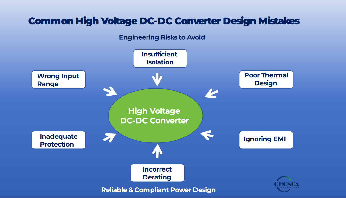
Common High Voltage DC-DC Converter Design Mistakes
Designing a high voltage DC-DC converter requires more than selecting a suitable input voltage, output voltage, and power rating.
A converter may meet its basic electrical specifications during laboratory testing and still experience reliability, thermal, EMI, protection, or EMC problems after integration into a real system.
Many of these problems come from design decisions that appear reasonable at the beginning of a project but do not adequately account for actual operating conditions.
The most common high voltage DC-DC converter design mistakes involve input-voltage assumptions, insufficient voltage margin, thermal design, component selection, isolation, protection, EMI control, and application-level validation.
Understanding these mistakes early can help engineers reduce redesign risk and improve long-term converter reliability.
Common High Voltage DC-DC Converter Design Mistakes
The following are among the most common mistakes engineers should avoid when designing or selecting a high voltage DC-DC converter:
- Designing around nominal input voltage only
- Ignoring input transients and surge conditions
- Selecting components too close to their maximum ratings
- Underestimating thermal stress
- Evaluating efficiency only at one operating point
- Treating isolation as a simple voltage specification
- Adding protection too late in the design
- Ignoring conducted and radiated EMI
- Focusing only on the converter instead of the complete power system
- Selecting a standard converter without checking the actual application conditions
Each mistake can affect converter reliability, efficiency, safety, or EMC performance.
Mistake 1 — Designing Around Nominal Input Voltage Only
One of the most common mistakes is designing a converter around the nominal input voltage while ignoring the actual voltage range of the system.
For example, a system may be described as a 48 VDC system.
However, the converter may actually experience:
- Lower operating voltage
- Normal voltage variation
- Higher operating voltage
- Startup conditions
- Load-dependent voltage changes
- Transient voltage
- Surge events
A 48 V nominal system therefore does not necessarily mean that the converter will continuously operate at exactly 48 V.
Engineers should define the actual minimum and maximum input voltage before selecting the converter.
This is particularly important for battery systems, railway power systems, telecommunications equipment, renewable-energy systems, and industrial equipment.
How to Avoid This Mistake
Define the complete input-voltage requirement at the beginning of the design:
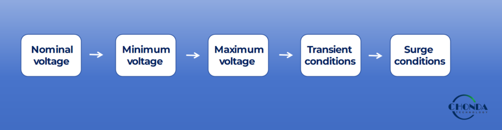
The converter’s specified operating range should then be compared with the actual system requirements.
📚 Continue Reading
Wide Input DC-DC Converter Design Guide
A wide-input converter can provide greater flexibility when the actual system voltage varies significantly.
Mistake 2 — Ignoring Input Transients and Surge Conditions
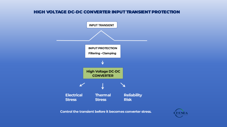
A converter may have a specified continuous operating range such as 100–1000 VDC, but this does not automatically describe how it behaves during every abnormal voltage event.
Real systems can experience short-duration voltage disturbances caused by:
- Switching events
- Load changes
- Regenerative energy
- Power-system disturbances
- Cable effects
- External surge events
Engineers therefore need to distinguish between the converter’s continuous operating range and its transient withstand capability.
These are different specifications and should not be treated as interchangeable.
How to Avoid This Mistake
When evaluating a high voltage DC-DC converter, check:
- Continuous input-voltage range
- Startup range
- Input overvoltage threshold
- Undervoltage threshold
- Transient withstand capability
- Surge protection requirements
- Required protection components
The correct design should be based on the actual electrical environment rather than the nominal supply voltage alone.
📚 Continue Reading
Wide Input Range Does Not Mean Unlimited Input Range
Mistake 3 — Selecting Components Too Close to Their Maximum Ratings
High voltage converter designs operate under electrical, thermal, and switching stress.
Selecting components simply because their maximum ratings are slightly above the normal operating voltage can leave insufficient design margin.
This can increase sensitivity to:
- Voltage spikes
- Temperature
- Aging
- Switching transients
- Manufacturing variation
- Abnormal operating conditions
Component ratings should therefore be evaluated against both normal operating conditions and expected transient conditions.
How to Avoid This Mistake
Engineers should consider appropriate voltage, current, temperature, and power margins during component selection.
Important components may include:
- Switching devices
- Rectifiers
- Capacitors
- Transformers
- Magnetics
- Isolation components
- Protection devices
The correct margin depends on the topology, operating conditions, safety requirements, and application.
The goal is not simply to select the largest-rated component. The goal is to establish a suitable engineering margin for the actual application.
Mistake 4 — Underestimating Thermal Stress
Electrical performance does not automatically guarantee reliable long-term operation.
Power losses inside the converter are converted into heat.
Thermal stress can affect:
- Semiconductor junction temperature
- Capacitor lifetime
- Transformer temperature
- Magnetic components
- PCB materials
- Insulation systems
- Overall converter reliability
The worst thermal operating point is not necessarily the lowest or highest input voltage.
It depends on the converter topology, switching conditions, load, efficiency profile, ambient temperature, and cooling environment.
How to Avoid This Mistake
Thermal analysis should consider the complete expected operating envelope.
Engineers should evaluate:
- Input voltage
- Output power
- Load profile
- Ambient temperature
- Efficiency
- Component losses
- Thermal resistance
- Cooling conditions
- Derating requirements
A converter should be evaluated at realistic worst-case conditions rather than only at room temperature and nominal load.
📚 Continue Reading
How to Improve High Voltage DC-DC Converter Reliability
Mistake 5 — Evaluating Efficiency at Only One Operating Point
Another common mistake is evaluating a converter based only on its peak efficiency.
For example, a converter may achieve excellent efficiency at one nominal input voltage and one particular load.
However, the application may operate across a much wider range.
Efficiency can change with:
- Input voltage
- Output power
- Load level
- Switching frequency
- Operating temperature
- Control conditions
A converter with high peak efficiency may therefore not provide the best overall system performance.
How to Avoid This Mistake
Engineers should examine efficiency across the expected operating range.
At minimum, consider:
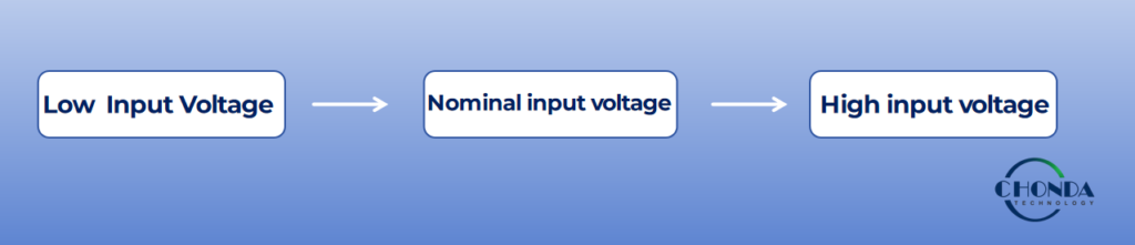
and:
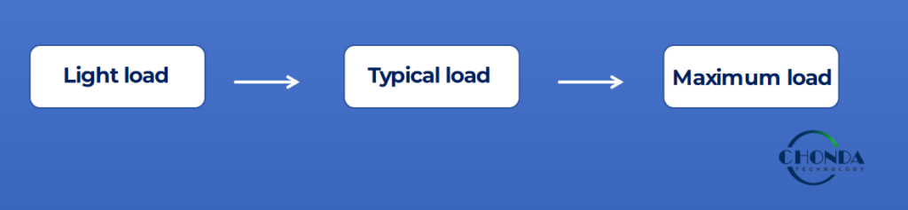
The most useful efficiency evaluation is therefore an efficiency map rather than a single headline efficiency number.
Mistake 6 — Treating Isolation as a Simple Voltage Rating
In high voltage DC-DC converters, isolation is more than a single voltage number.
Isolation design can involve:
- Isolation voltage
- Working voltage
- Clearance
- Creepage
- Insulation system
- Transformer construction
- PCB layout
- Environmental conditions
- Applicable safety requirements
A converter that appears to have sufficient isolation voltage may still require further evaluation when integrated into a real product.
How to Avoid This Mistake
Isolation requirements should be defined according to the complete system architecture and applicable safety requirements.
Engineers should consider both electrical specifications and physical implementation.
This is especially important in applications involving high voltage, industrial equipment, railway systems, medical equipment, and other safety-sensitive environments.
Mistake 7 — Adding Protection Too Late
Protection is sometimes treated as an additional feature after the main converter design has already been completed.
This approach can create problems because protection requirements are closely related to the converter topology, components, control strategy, thermal design, and system-level behavior.
Typical protection functions may include:
- Input overvoltage protection
- Undervoltage protection
- Overcurrent protection
- Short-circuit protection
- Overtemperature protection
- Reverse-polarity protection
- Surge protection
How to Avoid This Mistake
Protection requirements should be considered during the initial architecture stage.
Engineers should define:
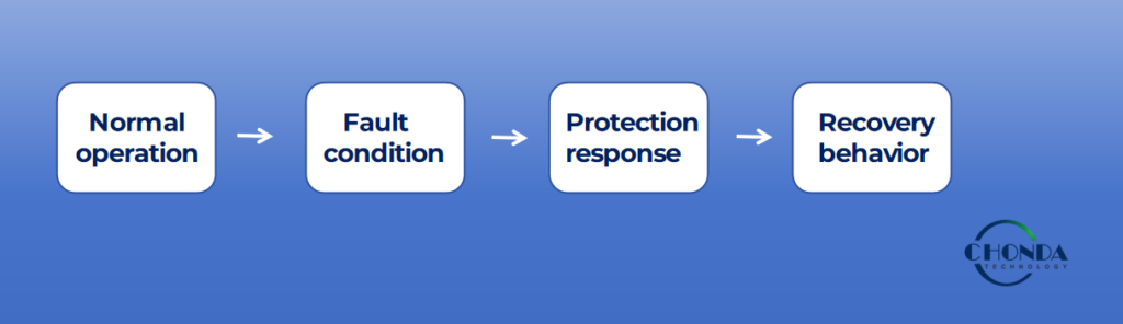
This helps ensure that the converter does not simply survive a fault, but responds to the fault in a controlled and predictable way.
Mistake 8 — Ignoring EMI and EMC During the Initial Design
EMI is often discovered late because a converter may operate normally even when it produces excessive electromagnetic noise.
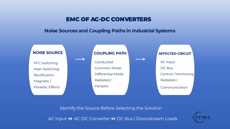
High voltage switching converters can generate both conducted and radiated electromagnetic interference.
Important factors include:
- High dv/dt
- High di/dt
- Switching loop area
- PCB layout
- Input filtering
- Output filtering
- Grounding
- Shielding
- Cable routing
- Transformer construction
Waiting until EMC testing to address these issues can result in costly redesign.
How to Avoid This Mistake
EMI and EMC should be considered during the earliest design stages.
The converter, PCB, cables, grounding, shielding, filtering, and mechanical enclosure should be treated as parts of the same electromagnetic system.
📚 Continue Reading
High Voltage DC-DC Converter Design Challenges
This article provides a broader discussion of EMI, thermal, isolation, reliability, and other engineering challenges.
Mistake 9 — Focusing Only on the Converter Instead of the Complete Power System
A DC-DC converter does not operate independently.
Its actual operating conditions are influenced by the complete system.
For example:
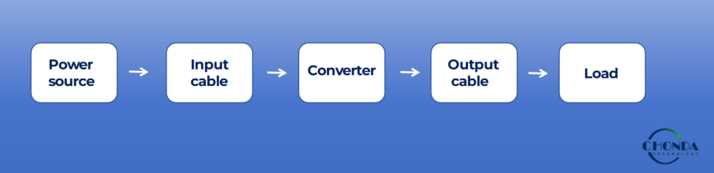
Each part can affect converter performance.
System-level factors may include:
- Source impedance
- Cable length
- Load characteristics
- Load transients
- Grounding
- Cooling
- Mechanical installation
- Environmental conditions
- Nearby electronic equipment
A converter that performs well in a laboratory setup may therefore behave differently after installation into the final equipment.
How to Avoid This Mistake
Validate the converter under conditions that represent the real application.
This should include realistic:
- Input voltage
- Output load
- Cable configuration
- Ambient temperature
- Transient conditions
- Mechanical installation
- EMI environment
Application-level validation is particularly important for demanding industrial and transportation systems.
Mistake 10 — Selecting a Standard Converter Without Checking the Complete Application
Standard converters can simplify development and shorten the engineering cycle.
However, selecting a product based only on input and output voltage can lead to compatibility problems.
Engineers should also evaluate:
- Input voltage range
- Output voltage
- Output power
- Isolation
- Efficiency
- Thermal performance
- Protection
- EMC / EMI
- Mechanical dimensions
- Pin definition
- Environmental requirements
- Annual operating conditions
A converter should therefore be selected according to the complete application requirement rather than a single electrical parameter.
How to Avoid This Mistake
Before selecting a converter, create an application checklist.

Only after these requirements are defined should the most suitable standard or customized converter be selected.
High Voltage DC-DC Converter Design Mistakes Checklist
Before finalizing a high voltage DC-DC converter design, engineers can use the following checklist:
Input
- Nominal input voltage defined
- Minimum input voltage defined
- Maximum input voltage defined
- Startup conditions evaluated
- Transient conditions evaluated
- Surge conditions evaluated
Electrical
- Output voltage defined
- Maximum output power defined
- Load profile evaluated
- Efficiency evaluated across the operating range
- Component voltage and current margins reviewed
Thermal
- Worst-case thermal condition identified
- Ambient temperature considered
- Component temperatures evaluated
- Thermal resistance reviewed
- Derating requirements defined
- Cooling conditions validated
Isolation and Protection
- Isolation requirement defined
- Insulation system evaluated
- Overvoltage protection reviewed
- Undervoltage protection reviewed
- Overcurrent protection reviewed
- Short-circuit behavior reviewed
- Overtemperature protection reviewed
EMC / EMI
- Conducted EMI evaluated
- Radiated EMI evaluated
- PCB layout reviewed
- Input filtering reviewed
- Grounding and shielding reviewed
- EMC compliance requirements identified
Application
- Cable conditions considered
- Load behavior considered
- Environmental conditions considered
- Mechanical integration reviewed
- Standard converter suitability confirmed
- Custom requirements identified
A checklist-based design review can help identify potential problems before prototype testing and system integration.
How to Avoid High Voltage DC-DC Converter Design Mistakes
The most effective way to reduce design mistakes is to define the complete operating environment before selecting the converter.
Engineers should avoid designing around nominal voltage alone, relying only on peak efficiency, ignoring thermal stress, or treating protection and EMC as late-stage requirements.
Instead, the converter should be evaluated across its expected electrical, thermal, mechanical, environmental, and electromagnetic conditions.
This approach helps transform converter selection from a simple specification-matching exercise into a system-level engineering decision.
CHONDA High Voltage DC-DC Converter Solutions
CHONDA provides isolated DC-DC converter solutions for applications requiring defined and demanding input-voltage conditions.
Depending on the application, engineers can evaluate standard converter solutions or discuss customized requirements involving:
- Input voltage range
- Output voltage
- Output power
- Isolation
- Protection
- Thermal requirements
- Mechanical integration
- Pin definition
- Application-specific electrical parameters
For projects where standard specifications do not fully cover the required operating conditions, CHONDA can discuss custom and OEM power-supply requirements with customers.
The appropriate solution should always be selected according to the actual application conditions and required operating range.
Frequently Asked Questions
What is the most common high voltage DC-DC converter design mistake?
One of the most common mistakes is designing around nominal input voltage without considering the complete operating range, transient conditions, load profile, thermal environment, and protection requirements.
Why is thermal design important in high voltage DC-DC converters?
Power losses generate heat, and excessive temperature can reduce component lifetime and converter reliability. Thermal performance should therefore be evaluated across the expected input-voltage, load, and ambient-temperature range.
Does higher efficiency always mean better converter reliability?
Not necessarily. Efficiency is important, but reliability also depends on component selection, thermal stress, isolation, protection, operating conditions, and application environment.
Why should engineers consider EMI during the early design stage?
EMI can be strongly affected by PCB layout, switching transitions, filtering, grounding, shielding, and cable routing. Addressing these factors early can reduce the risk of EMC compliance failures and redesign.
What should be checked before selecting a high voltage DC-DC converter?
Engineers should check input range, output voltage, output power, efficiency, thermal performance, isolation, protection, EMC / EMI requirements, mechanical constraints, and environmental conditions.
When is a custom DC-DC converter necessary?
A custom solution may be appropriate when the required input range, output characteristics, isolation, power level, mechanical dimensions, pin definition, or other electrical requirements cannot be adequately covered by a standard converter.
How can engineers reduce high voltage DC-DC converter design risk?
Define the complete application requirements first, including nominal and operating voltage, transient conditions, output power, thermal conditions, isolation, protection, EMI, and mechanical integration. Then select and validate the converter against those requirements.
Can CHONDA provide customized high voltage DC-DC converter solutions?
CHONDA can discuss standard and customized isolated DC-DC converter requirements based on the customer’s electrical, mechanical, isolation, thermal, and application conditions.
Conclusion
Avoiding common high voltage DC-DC converter design mistakes requires engineers to look beyond basic voltage and power specifications.
A reliable design must account for the complete operating environment, including input variation, transient conditions, component margins, thermal stress, isolation, protection, EMI, EMC, mechanical integration, and real application conditions.
The earlier these factors are considered, the lower the risk of unexpected performance problems during prototype testing, EMC qualification, and long-term operation.
For demanding applications, a high voltage DC-DC converter should therefore be treated as part of the complete power system rather than as an isolated component.
CHONDA provides standard and customized isolated DC-DC converter solutions for industrial, railway, renewable-energy, telecommunications, and other demanding power applications.
Related Articles
- Wide Input DC-DC Converter Design Guide
Understand how input-voltage range, regulation, efficiency, thermal performance, protection, and EMC requirements affect wide-input converter selection. - How to Improve High Voltage DC-DC Converter Reliability
Explore the key engineering factors that influence long-term converter reliability, including component selection, derating, thermal management, isolation, and protection. - High Voltage DC-DC Converter Design Challenges
Learn about the major engineering challenges in high voltage DC-DC converter design, including isolation, efficiency, thermal management, EMI, reliability, and system-level trade-offs. - Railway DC-DC Converter
Understand the power-conversion requirements of railway systems and why input-voltage variation, transient conditions, isolation, and reliability are critical. - PV Monitoring Power Supply
Explore DC-DC power requirements for PV string monitoring and high-voltage photovoltaic applications.