We help the world since 2012

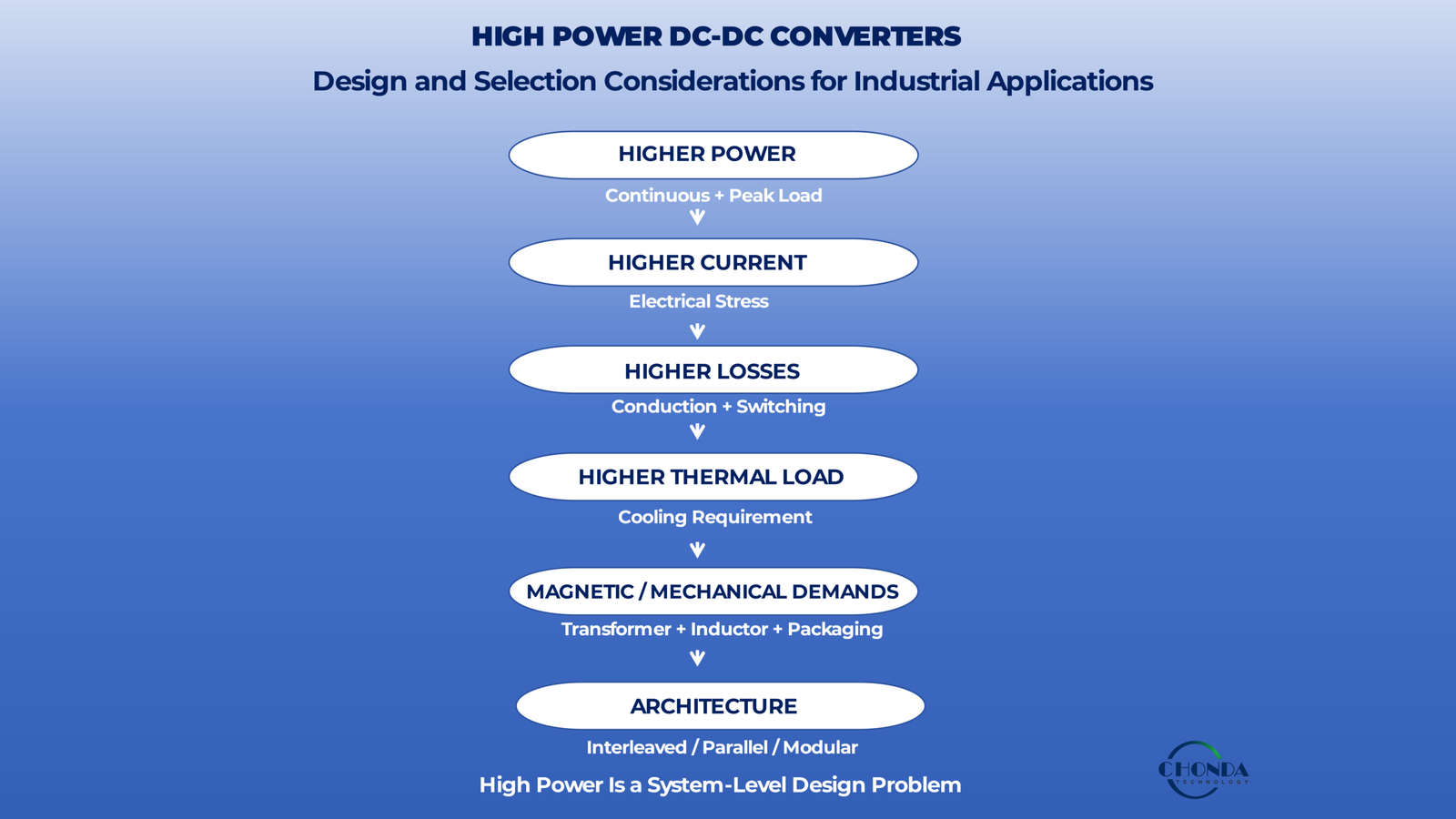
High Power DC-DC Converters: Design and Selection Considerations
As the power level of a DC-DC converter increases, the design problem changes.
A converter that works well at a relatively modest power level cannot always be scaled upward simply by using larger components.
Higher power introduces new constraints involving input and output current, semiconductor stress, magnetic losses, thermal density, switching behavior, mechanical packaging, and overall system efficiency.
A simplified power path may still look like:
DC Input → DC-DC Conversion → DC Output
but the engineering decisions behind that path can become significantly more demanding as power increases.
For example, increasing output power may require higher current on the low-voltage side. This can increase conduction losses in semiconductors, PCB copper, connectors, inductors, transformers, and cables.
At the same time, higher power often means more heat must be removed from a limited physical volume.
A design may therefore become thermally constrained before the semiconductor or magnetic components reach their theoretical electrical limits.
High-power conversion can also change the preferred architecture.
Depending on the application, engineers may need to consider higher-power switching devices, larger magnetic components, multiple power stages, interleaved or parallel conversion paths, modular architectures, or different cooling structures.
This means that high power is not simply a larger version of low power.
The converter must be evaluated as a complete power system in which electrical stress, efficiency, thermal performance, magnetic design, mechanical integration, and reliability interact.
This guide examines the key design and selection considerations for high-power DC-DC converters, with a focus on the engineering trade-offs that become increasingly important as converter power increases.
The goal is not simply to choose a converter with a higher power rating.
It is to select or design a high-power DC-DC conversion system that can deliver the required power continuously and reliably under the real electrical, thermal, mechanical, and environmental conditions of the application.
1. What Makes a DC-DC Converter “High Power”?
There is no universal power level at which a DC-DC converter suddenly becomes a “high-power” converter.
A few hundred watts may represent a demanding design in one application, while several kilowatts may be routine in another.
For this reason, high power is better understood as an engineering condition than as a fixed wattage threshold.
The more useful question is:
At what power level do current, thermal, magnetic, switching, mechanical, and reliability requirements begin to dominate the converter design?
As output power increases, these constraints become increasingly interconnected.
1.1 Power Level Changes the Electrical Problem
At a basic level:
Power = Voltage × Current
For a given output voltage, increasing power means increasing output current.
For example, the current required by a 24V output is very different at 100W and 1kW.
A simplified comparison is:
100W / 24V ≈ 4.2A
while:
1kW / 24V ≈ 41.7A
The nominal output voltage has not changed, but the electrical implementation is now very different.
Higher current affects semiconductor conduction losses, PCB copper, connectors, inductors, transformers, cables, and protection structures.
This is one of the first reasons why high-power conversion becomes a different engineering problem.
1.2 High Power Does Not Mean High Voltage
A high-power converter does not necessarily have a high-voltage output.
For example, an industrial converter may process a relatively high-voltage DC input and deliver a low-voltage, high-current output.
Another converter may process a lower-voltage input while delivering substantially more output power.
The two systems may therefore have very different electrical constraints even though both can be described as high-power converters.
This is why power level, voltage level, and current level should be considered separately.
1.3 Input Power Can Also Be Significant
The converter must process more power than it ultimately delivers because some energy is lost during conversion.
For example, if a converter delivers 2kW at 95% efficiency, the input power is approximately:
2kW / 0.95 ≈ 2.11kW
The difference becomes heat within the converter.
As power increases, even a relatively small percentage of loss can represent a substantial absolute amount of heat.
This is one reason efficiency becomes increasingly important in high-power applications.
1.4 High Power Increases the Importance of Loss Distribution
The total power loss is important, but its physical distribution also matters.
Suppose two converters both dissipate 50W.
One design may distribute those losses across several switching devices, magnetic components, and passive parts.
Another may concentrate a large portion of the loss in one semiconductor or transformer winding.
The second design may develop a more difficult thermal problem even though the total loss is identical.
High-power design therefore requires engineers to consider not only:
How much power is lost?
but also:
Where is that power being lost?
1.5 Thermal Constraints Become More Visible
At lower power, a converter may be able to rely on relatively simple heat spreading and natural convection.
As power increases, the same physical volume may need to remove significantly more heat.
The resulting thermal density can become a primary design constraint.
For example:
Higher Output Power → Higher Losses → Higher Heat Generation → Greater Cooling Requirement
This can eventually determine the allowable continuous power of the converter.
The electrical design may be capable of processing the required current while the physical system is unable to remove the associated heat.
1.6 Magnetic Components Scale Differently Than Power
Increasing power does not simply mean making the transformer or inductor proportionally larger.
Magnetic components must balance:
- Core size
- Flux density
- Winding current
- Copper loss
- Core loss
- Insulation
- Temperature rise
- Available physical space
At higher power levels, the winding structure and thermal path may become just as important as the magnetic core itself.
This can lead engineers to consider different winding arrangements, conductor structures, cooling methods, or even different converter architectures.
1.7 Switching Devices Experience Greater Stress
Higher power can also increase the electrical stress on switching devices.
Depending on the converter topology and operating conditions, engineers may need to manage:
- Higher current
- Higher conduction loss
- Switching loss
- Voltage overshoot
- Thermal stress
- Safe operating area
The device selection process therefore becomes increasingly important as power rises.
A device that performs well in a lower-power design may no longer be the most practical choice when current and thermal requirements increase substantially.
1.8 High Power Can Change the Preferred Architecture
At some point, simply scaling one converter stage upward may become less attractive.
Engineers may instead consider:
Multi-Stage Conversion
Interleaved Conversion
Parallel Power Stages
Modular Architectures
These approaches can distribute current, thermal load, switching stress, or magnetic requirements across several conversion paths.
The preferred architecture depends on the application.
The important point is that higher power can change the architecture itself, not just the size of individual components.
1.9 Continuous Power Matters More Than a Single Peak Number
A converter may briefly process a high power level without being designed for continuous operation at that level.
For industrial applications, engineers should therefore distinguish between:
Continuous Power
Peak Power
Pulse Duration
Duty Cycle
A converter that can deliver 5kW for a short transient is not equivalent to a converter designed to deliver 5kW continuously in a high-ambient industrial enclosure.
The thermal and reliability requirements can be very different.
1.10 High Power Is Application-Dependent
The most useful definition is therefore not:
“High power means more than X watts.”
A better engineering definition is:
A high-power DC-DC converter is a converter whose power level creates significant electrical, thermal, magnetic, mechanical, or architectural constraints that must be addressed as part of the complete design.
This definition remains useful across different industries and voltage ranges.
For a compact industrial control system, a relatively modest output power may already create significant current and thermal constraints.
For a large industrial power platform, the same power level may be comparatively ordinary.
1.11 The Practical Starting Point
When evaluating whether a DC-DC converter should be treated as a high-power design problem, engineers should consider:
Output Power
Input / Output Voltage
Continuous Current
Peak Current
Power-Loss Budget
Thermal Environment
Magnetic Requirements
Physical Size
Expected Operating Duty
These factors together provide a much more meaningful picture than a single wattage threshold.
The key principle is:
High power is not simply about the number of watts. It is about when power level begins to dominate the electrical, thermal, magnetic, mechanical, and architectural decisions of the converter.
Once this point is established, the next question becomes more concrete: how does increasing power change current levels and electrical stress inside the converter?
2. Higher Power Means Higher Current and Electrical Stress
As the power level of a DC-DC converter increases, current becomes one of the first physical constraints that begins to dominate the design.
For a given voltage, higher power requires higher current:
Power = Voltage × Current
This relationship is simple, but its consequences are significant.
Higher current increases conduction losses, electrical stress, thermal loading, and the requirements placed on semiconductors, magnetic components, PCB structures, connectors, and cables.
This is one of the main reasons why a high-power DC-DC converter cannot always be created by simply scaling the components of a lower-power design.
2.1 Higher Output Power Drives Higher Current
Consider a low-voltage output.
At 24V, a 100W load requires approximately:
100W / 24V ≈ 4.2A
A 1kW load at the same voltage requires approximately:
1000W / 24V ≈ 41.7A
The output voltage has not changed.
The power level has increased by a factor of ten, but the output current has also increased by a factor of ten.
This affects nearly every conductive element in the power path.
2.2 Conduction Loss Increases with Current
Conduction loss is strongly influenced by current.
For a resistive path, the relationship can be represented conceptually as:
Conduction Loss ∝ Current² × Resistance
This means that even a moderate increase in current can produce a much larger increase in conduction loss.
For example, if current doubles while resistance remains approximately constant, the associated resistive loss can increase by roughly four times.
This effect applies to:
- Semiconductor on-state resistance
- Transformer windings
- Inductor windings
- PCB copper
- Connectors
- Bus bars
- Cables
As converter power rises, minimizing unnecessary resistance becomes increasingly important.
2.3 Low-Voltage Outputs Can Become Current-Intensive
A high-power converter with a low-voltage output can become particularly demanding on the output side.
For example:
2kW / 24V ≈ 83A
At this current level, the design challenge is no longer only the DC-DC switching stage.
The output path itself becomes a significant engineering problem.
PCB copper width, parallel current paths, connectors, bus structures, conductor selection, and voltage drop all become important.
This is why high-power, low-voltage outputs often require substantially different physical implementation from lower-power designs.
2.4 Higher Current Increases Voltage Drop
Every real conductor has resistance.
As current increases, the voltage drop across that resistance also increases.
A simplified relationship is:
Voltage Drop = Current × Resistance
This means that a conductor that creates only a small voltage drop at low current can become significant at high current.
For example, a small resistance in a connector or PCB path may appear negligible during a low-power prototype test but become an important source of voltage drop when the converter operates at much higher current.
The resulting drop can affect output regulation and system efficiency.
2.5 Switching Devices Experience Greater Current Stress
Higher converter power also increases the current stress experienced by the switching devices.
Depending on the topology, the semiconductor may need to withstand:
- Higher RMS current
- Higher peak current
- Higher pulsed current
- Increased conduction loss
- Increased thermal stress
The required current rating is therefore not determined by output current alone.
The actual device current waveform, duty cycle, switching strategy, and topology also influence the electrical stress.
A semiconductor selected only from the nominal output current may therefore be insufficient.
2.6 Peak Current Can Be More Important Than Average Current
In many converters, the current flowing through a switching device or magnetic component is not constant.
The component may experience a relatively moderate average current but much larger peak or ripple currents.
For example:
Average Current < RMS Current < Peak Current
depending on the waveform and topology.
These different current values affect different aspects of the design.
RMS current is particularly important for resistive and thermal losses, while peak current can influence semiconductor stress, magnetic saturation, current sensing, and protection behavior.
A proper high-power design therefore needs to understand the complete current waveform rather than relying on one current number.
2.7 Magnetic Components Also See Higher Current Stress
Transformers and inductors are strongly affected by increasing current.
Higher winding current can increase:
- Copper loss
- Winding temperature
- Current density
- Voltage drop
- Conductor requirements
If the magnetic design is not adjusted appropriately, the converter may experience excessive winding temperature even when the semiconductor stage remains within its expected operating range.
At higher power levels, winding construction can therefore become a major design variable.
2.8 PCB Copper Becomes Part of the Power Stage
At high current, PCB copper is no longer just a passive connection between components.
It becomes part of the power-conversion path.
The engineer may need to consider:
- Copper thickness
- Copper width
- Parallel layers
- Thermal spreading
- Via current
- Current density
- Connection resistance
A high-power converter can therefore require substantially different PCB construction from a low-power converter even when the electrical topology is unchanged.
2.9 Connectors and Interconnections Can Become Limiting Elements
Connectors, terminals, bus bars, and cables can also become significant at higher current.
A connector with an adequate nominal rating may still experience:
- Contact resistance
- Local heating
- Voltage drop
- Mechanical limitations
The power path should therefore be evaluated as a complete chain:
Semiconductor → Magnetic Component → PCB → Connector → Cable → Load
The weakest conductive element can become the effective limitation.
2.10 Higher Current Also Increases Fault Energy
Higher current means that a short circuit or abnormal load condition can involve significantly more energy.
This can increase the demands on:
- Over-current protection
- Current sensing
- Fuses
- Switching devices
- Connectors
- PCB structures
Protection should therefore be considered together with the electrical power path rather than added after the power stage has been finalized.
2.11 Electrical Stress Is Not Only About Current
Higher power can also increase voltage and switching stress depending on the converter architecture.
For example, a topology operating from a high-voltage input may experience both:
High Input Voltage
and:
High Switching Current
This combination can create demanding conditions for the semiconductor, insulation system, magnetic components, and layout.
High-power design therefore needs to consider both voltage stress and current stress together.
2.12 The Current Challenge Is a System-Level Challenge
Once converter power becomes high enough, the current no longer belongs to one component.
It affects the entire power path.
A useful way to think about the problem is:
Higher Power
↓
Higher Current
↓
Higher Conduction Loss
↓
Higher Voltage Drop + Higher Heat
↓
Greater Electrical and Thermal Stress
This chain explains why high-power converters often require changes in semiconductor selection, magnetic construction, PCB design, interconnections, and protection.
2.13 The Practical Engineering Principle
When evaluating a high-power DC-DC converter, engineers should not ask only:
“Can the converter deliver the required power?”
They should also ask:
“Can every part of the current path carry that power efficiently, safely, and continuously?”
This includes the switching devices, magnetic components, PCB, connectors, conductors, and protection system.
The key principle is:
As converter power increases, current becomes a system-level design constraint rather than simply a larger number on the datasheet.
Once the current and electrical-stress problem is understood, the next question is whether the resulting power losses can be removed reliably from the converter.
3. Thermal Design Becomes a Primary Constraint
As the power level of a DC-DC converter increases, thermal design can move from being an important consideration to becoming one of the primary constraints that determines the practical limits of the converter.
The reason is straightforward.
Even when converter efficiency remains high, the absolute amount of power that becomes heat can become substantial at high output power.
For example, a converter delivering 5kW at 96% efficiency still dissipates more than 200W internally.
That heat must be transferred away continuously while keeping critical components within their allowable temperature range.
3.1 High Power Makes Small Percentage Losses More Significant
Efficiency is often expressed as a percentage, but thermal design is driven by the absolute power that is lost.
Consider two converters operating at the same 95% efficiency.
A 200W converter loses approximately:
200W × 5% = 10W
A 5kW converter loses approximately:
5000W × 5% = 250W
The efficiency figure is identical.
The thermal problem is not.
As converter power increases, even a small percentage of inefficiency can become a large amount of heat that the system must continuously remove.
3.2 Heat Generation Increases the Importance of Physical Volume
More heat does not automatically mean that a converter can simply be made larger.
Industrial equipment often has strict limits on:
- Enclosure size
- Mounting space
- Weight
- Cooling structure
- Airflow
This creates a practical relationship:
Higher Power + Limited Volume → Higher Thermal Density
At some point, the physical volume available for heat spreading and cooling becomes just as important as the electrical power rating.
3.3 Continuous Power Is a Thermal Problem
A converter may be capable of handling a high peak power for a short period without being capable of delivering that same power continuously.
The difference is the amount of time available for heat to accumulate and leave the system.
For example:
Peak Power → Short Duration
may be limited primarily by electrical and control considerations.
By contrast:
Continuous Power → Long-Duration Thermal Equilibrium
can become the true limiting condition.
For industrial applications, continuous operating power is therefore closely linked to the thermal capability of the converter.
3.4 Higher Power Creates More Heat Inside the Same Architecture
If the electrical architecture remains unchanged while the output power increases, several loss mechanisms can grow at the same time.
Higher current can increase conduction losses.
Higher switching activity can increase switching losses.
Magnetic components can experience greater winding and core losses.
PCB and interconnection losses can also increase.
The result is:
Higher Power → Higher Total Loss → Higher Heat Load
The converter must then provide a thermal path capable of handling that additional heat continuously.
3.5 Thermal Density Can Become a Packaging Constraint
At higher power levels, the challenge is often no longer simply:
Can the components survive the temperature?
It becomes:
Can the entire converter package remove the required heat within the available space?
A design may have electrically suitable semiconductors and magnetic components but still require a larger enclosure, improved heat spreading, forced airflow, liquid cooling, or another thermal strategy.
Thermal design can therefore influence the mechanical architecture of the converter.
3.6 Component Placement Becomes More Important
As power increases, multiple high-loss components may need to operate within a relatively small physical area.
This can create local regions of elevated temperature.
For example:
Switching Devices + Magnetic Components + Rectification Devices
may all generate heat simultaneously.
If these components are placed too closely together, their thermal environments can interact.
The local ambient temperature seen by one component may therefore be significantly higher than the external ambient temperature of the equipment.
3.7 Thermal Margin Becomes More Valuable
A converter that operates very close to its maximum allowable temperature may have limited margin against real-world variation.
Industrial equipment can experience:
- Higher ambient temperature
- Reduced airflow
- Dust or contamination
- Installation variation
- Component tolerance
- Aging
As power increases, thermal margin becomes increasingly important because the absolute heat load is larger and the consequences of losing cooling capability can become more severe.
The practical objective is therefore not simply to remain below a specified maximum temperature.
It is to maintain enough thermal margin for the expected operating environment.
3.8 Cooling Requirements Can Affect System Architecture
Higher-power converters may require more than a larger heat sink.
The cooling strategy can influence:
- Enclosure dimensions
- Fan placement
- Heat-spreader design
- Mechanical mounting
- Component spacing
- Airflow direction
- Service requirements
In some applications, the cooling architecture may need to be considered at the same time as the electrical architecture.
This is particularly true when the converter is installed inside a sealed or densely packed industrial system.
3.9 Thermal Performance Can Limit Practical Power Rating
A converter may have semiconductors and magnetic components with sufficient theoretical electrical ratings, but if the thermal system cannot continuously remove the resulting losses, the practical continuous power rating must be reduced.
This is why datasheet power capability should always be interpreted together with the specified thermal conditions.
For example:
Rated Power at Controlled Ambient
is not necessarily equivalent to:
Rated Power Inside the Final Equipment
The installation environment can change the actual usable power.
3.10 High Power Can Shift the Design Objective
At lower power levels, engineers may prioritize:
Efficiency + Cost + Size
As power increases, the priority may shift toward:
Efficiency + Thermal Capability + Reliability + Power Density
The reason is not that cost or size stop mattering.
Rather, thermal performance begins to place stronger limits on what is physically possible.
3.11 Thermal Design Should Begin Before the Final Package
Because thermal limitations can affect the size, architecture, and component selection of a high-power converter, thermal analysis should not be postponed until the mechanical design is complete.
Early estimates of:
- Semiconductor losses
- Magnetic losses
- Conduction losses
- Expected ambient temperature
- Cooling capability
can reveal whether the intended power level is physically realistic.
This allows the design team to reconsider the architecture before expensive hardware changes are required.
3.12 The Practical Engineering Principle
The main lesson is:
At high power, thermal capability can become the practical limit of the converter even when the electrical circuit is capable of processing the required power.
The relevant question is therefore not simply:
“Can the converter handle the current?”
It is:
“Can the converter continuously remove the heat generated while maintaining sufficient temperature margin under the real installation conditions?”
This is why high-power DC-DC converter design must treat thermal capability as a primary design constraint rather than as a final-stage cooling problem.
The next step is to examine how transformers, inductors, core materials, and winding structures must change when power increases and why magnetic components often become one of the most difficult parts of a high-power converter to scale.
4. Magnetic Components in High-Power DC-DC Converters
Magnetic components are often among the most important design elements in a high-power DC-DC converter.
Transformers and inductors do more than transfer or store energy. At higher power levels, their core size, winding structure, conductor selection, insulation, losses, and thermal behavior can become major factors that determine the practical performance of the converter.
This is because increasing converter power places greater demands on both the magnetic core and the windings.
A useful relationship is:
Higher Power → Higher Current → Higher Magnetic Stress → Higher Loss and Thermal Demand
4.1 Why Magnetics Become More Difficult at Higher Power
A higher-power converter must transfer or store more energy during each switching cycle.
This can increase the current flowing through transformer and inductor windings and can increase the amount of magnetic material required to keep flux density and temperature within acceptable limits.
The challenge is therefore not simply to build a larger magnetic component.
The engineer must balance:
Core Size + Winding Space + Current Density + Loss + Thermal Path + Insulation + Physical Volume
A larger core may provide more magnetic capability, but it may also increase size, weight, cost, and thermal-path length.
4.2 Transformer Design
In an isolated high-power DC-DC converter, the transformer is often one of the most critical components.
It must simultaneously provide:
- Energy transfer
- Voltage transformation
- Electrical isolation
- Acceptable leakage inductance
- Controlled parasitic capacitance
- Appropriate thermal performance
As power increases, the winding must carry more current while maintaining acceptable temperature rise.
At the same time, the insulation system must continue to satisfy the required isolation conditions.
This creates a multi-variable design problem rather than a simple turns-ratio calculation.
4.3 Core Size and Flux Density
The magnetic core must operate within an appropriate flux-density range.
If the design pushes the core too close to saturation, a relatively small increase in current or operating condition can produce a much larger increase in magnetizing current and loss.
Higher power therefore often requires careful management of:
Core Area + Turns + Flux Density + Frequency
The goal is to transfer the required energy without creating excessive core loss or approaching an unstable magnetic operating region.
4.4 Core Loss Becomes More Significant
Core loss is influenced by factors such as:
- Frequency
- Flux density
- Core material
- Waveform
- Temperature
A design that appears acceptable at moderate power may become thermally limited as the magnetic operating point changes.
The core must therefore be selected for the actual frequency and flux conditions rather than simply for its physical size.
Increasing core size alone does not guarantee lower loss if the magnetic operating point remains inappropriate.
4.5 Winding Loss Can Become a Major Limitation
At higher power, winding current becomes one of the most important concerns.
Copper loss increases as current and effective winding resistance increase.
A simple relationship is:
Winding Loss ∝ I²R
This means that current increases can cause winding losses to grow rapidly.
At high switching frequency, the effective resistance can also be influenced by skin effect and proximity effect, making conductor geometry increasingly important.
The winding therefore becomes both an electrical and thermal design problem.
4.6 Conductor Selection Changes With Power
A higher-current winding may require a larger conductor cross-sectional area.
However, simply using a very thick conductor is not always the best solution at high frequency.
Engineers may instead consider:
- Parallel conductors
- Foil windings
- Litz wire
- Specialized winding structures
The appropriate approach depends on the current waveform, switching frequency, available winding window, insulation requirements, and manufacturing method.
The goal is to achieve the required current capability while controlling AC resistance and thermal behavior.
4.7 Winding Window Becomes a Practical Constraint
The transformer winding has only a finite amount of available space.
That space must accommodate:
Conductor + Insulation + Spacing + Multiple Windings
As power increases, the current-carrying conductor may need to become larger while the isolation structure still requires sufficient creepage and clearance.
This creates a practical trade-off:
Higher Current Capability ↔ Available Winding Space
A magnetic design that looks feasible electrically may therefore become difficult to manufacture physically.
4.8 Isolation Adds Another Dimension
For an isolated high-power converter, transformer design must also satisfy the required insulation system.
The winding structure may need to accommodate:
- Primary-to-secondary insulation
- Creepage
- Clearance
- Insulation thickness
- Safety margins
- Transient voltage stress
These requirements consume physical space that could otherwise be used for copper.
This is one reason high-power isolated transformers can become significantly larger than a simple magnetic-power calculation would suggest.
4.9 Thermal Performance of Magnetics
Magnetic losses eventually become heat.
This heat may come from:
Core Loss + Winding Loss + Other Magnetic Losses
The difficulty is that some of this heat can be generated inside the winding or core rather than directly on an easily cooled external surface.
The magnetic component therefore needs a practical thermal path from its internal loss sources to the surrounding structure.
In a compact high-power converter, magnetic thermal performance can become a major constraint on continuous power.
4.10 Power Density Creates a Difficult Trade-Off
Engineers often want a high-power converter to remain compact.
This creates the familiar trade-off:
Higher Power Density
versus:
Lower Thermal Density + Larger Magnetic Volume
Reducing transformer or inductor size may improve packaging and reduce weight.
However, higher magnetic loss density can make cooling more difficult.
Conversely, using a larger magnetic structure may improve thermal performance while increasing system size.
The correct choice depends on the application’s priorities.
4.11 Inductors Face Similar Constraints
High-power inductors also need to manage both electrical and thermal stress.
As current increases, the designer must consider:
Saturation Current
Copper Loss
Core Loss
Temperature Rise
Energy Storage
A suitable inductive component must store or transfer the required energy without excessive core saturation or temperature rise.
This becomes particularly important in high-current output stages where the inductor may carry substantial ripple current in addition to the average load current.
4.12 Ripple Current Should Not Be Ignored
The average current does not fully describe the stress experienced by a high-power inductor or transformer winding.
Ripple current can increase RMS current and therefore increase copper-related losses.
For example:
Average Current + Ripple Current → Higher RMS Current → Higher Winding Loss
The current waveform should therefore be considered when sizing conductors and evaluating thermal performance.
4.13 Magnetic Design Influences the Rest of the Converter
The magnetic components do not operate independently from the rest of the system.
Changing the transformer or inductor can influence:
- Switching behavior
- Leakage inductance
- EMI
- Efficiency
- Thermal distribution
- Mechanical size
- Insulation structure
For example, reducing leakage inductance may improve one aspect of switching performance while requiring a different winding structure.
Likewise, increasing magnetic size may improve thermal margin while reducing power density.
This is why magnetic design should be developed together with the switching stage and mechanical structure.
4.14 High-Power Magnetics Are Often a System-Level Bottleneck
At higher power levels, the transformer or inductor can become the component that determines the practical limit of the converter.
The semiconductor devices may have adequate voltage and current ratings, but the magnetic components may become too large, too hot, or too difficult to manufacture within the required enclosure.
This creates an important engineering distinction:
Electrical capability does not automatically mean practical magnetic capability.
The magnetic design must fit the electrical, thermal, mechanical, and manufacturing requirements of the final converter.
4.15 The Practical Engineering Principle
The key question in high-power magnetic design is not:
“How large should the transformer or inductor be?”
It is:
“How can the magnetic component transfer or store the required energy while keeping core loss, winding loss, thermal density, insulation, and physical size within acceptable limits?”
This is why magnetics often become one of the most difficult parts of a high-power DC-DC converter to scale.
A successful design balances core performance, winding construction, loss, thermal behavior, insulation, and power density rather than optimizing any single characteristic in isolation.
The next design question is how switching frequency affects these magnetic losses and the overall efficiency of a high-power converter.
5. Switching Frequency and Efficiency Trade-Offs
Increasing switching frequency can provide important benefits in DC-DC converter design.
Higher frequency can reduce the size of magnetic components, increase power density, and in some cases allow the converter to respond more quickly to changes in load.
However, as converter power increases, the cost of switching also becomes more significant.
This creates an important engineering trade-off:
Higher Switching Frequency → Smaller Magnetics
but potentially:
Higher Switching Frequency → Higher Switching Losses → Higher Thermal Load
The optimum frequency is therefore not necessarily the highest frequency that the semiconductor devices can support.
5.1 Why Higher Frequency Is Attractive
Increasing switching frequency allows the converter to transfer energy more often during a given period of time.
This can reduce the energy that must be transferred during each individual switching cycle and can allow smaller inductors, transformers, and filters.
For compact equipment, this can provide an important packaging advantage.
However, the benefit of smaller magnetic components needs to be considered together with the additional switching losses created by operating more frequently.
5.2 Switching Loss Grows with Switching Activity
Every switching transition requires energy.
As switching frequency increases, the number of switching events occurring per second also increases.
In practical terms:
More Switching Events per Second → More Switching Energy per Second
The result can be higher switching loss in the semiconductor devices and associated gate-drive circuitry.
At relatively low power, this additional loss may be manageable.
At high power, the absolute amount of heat generated by the switching stage can become substantial.
5.3 High Power Makes the Trade-Off More Visible
Consider two high-power converter designs that deliver the same output power.
One operates at a moderate switching frequency and uses larger magnetic components.
The other operates at a significantly higher frequency and uses smaller magnetics.
The second design may reduce:
- Transformer volume
- Inductor volume
- Filter size
- Overall converter footprint
But it may also increase:
- Switching losses
- Gate-drive losses
- EMI challenges
- Thermal load
The smaller magnetic package therefore does not necessarily result in a better overall converter.
5.4 Magnetic Benefits Have a Practical Limit
Higher frequency can help reduce magnetic size, but the benefit is not unlimited.
As frequency increases, magnetic losses can also become more important.
The transformer or inductor must manage the interaction between:
Frequency + Flux Density + Core Material + Winding Structure
At some point, reducing component size further may create more magnetic loss and thermal difficulty than the packaging benefit is worth.
The optimum design therefore balances magnetic size against magnetic efficiency and thermal capability.
5.5 Switching Frequency Affects Thermal Design
The switching stage is usually one of the major heat sources in a high-power converter.
If frequency is increased significantly, the additional switching loss can increase the amount of heat that must be removed from the semiconductor devices and their surrounding structures.
This can affect:
- Heat-sink requirements
- PCB temperature
- Cooling capacity
- Component spacing
- Enclosure size
The frequency decision therefore becomes partly a thermal decision.
5.6 Switching Frequency Also Affects EMI
Higher switching frequency generally creates more high-frequency switching activity.
This can increase the difficulty of controlling:
- Conducted noise
- Radiated emissions
- Common-mode currents
- Switching-node ringing
The EMC consequences become increasingly important when high switching speed is combined with high voltage and high current.
For high-power converters, the frequency selected for power density must therefore also be acceptable from an EMI perspective.
5.7 Higher Frequency Can Increase the Importance of Parasitics
At higher frequency, parasitic inductance and capacitance become more influential.
Small amounts of:
- Stray capacitance
- PCB inductance
- Package inductance
- Transformer parasitic capacitance
can interact with the faster switching transitions.
This can create ringing and overshoot that increase both electrical stress and EMI.
A frequency that looks attractive from a magnetic-size perspective may therefore become difficult to implement physically.
5.8 The Semiconductor Technology Matters
The practical switching-frequency limit also depends on the switching devices being used.
Different semiconductor technologies have different characteristics in terms of:
- Switching speed
- Conduction loss
- Switching loss
- Voltage capability
- Thermal performance
A frequency that is practical with one semiconductor technology may be much less attractive with another.
This is one reason frequency should be selected together with the semiconductor technology rather than as an isolated design variable.
5.9 High Power May Favor Distributed Switching
As power increases, engineers may choose architectures that distribute the conversion burden across multiple power stages.
For example:
Parallel Power Stages
or:
Interleaved Conversion
can spread current and thermal stress across several switching paths.
In these architectures, the goal may not be to maximize the switching frequency of one power stage.
Instead, the system can achieve the required performance by distributing power across multiple phases or modules.
This can change the practical frequency trade-off.
5.10 Frequency Should Follow the System Objective
A useful design question is not:
“What is the highest switching frequency we can use?”
It is:
“What switching frequency gives the best overall balance between magnetic size, efficiency, thermal performance, EMI, and reliability?”
This becomes particularly important in high-power systems where even a small increase in switching loss can represent a significant additional thermal load.
5.11 A Practical Frequency Selection Process
A practical approach can be:
Define Power Level
↓
Estimate Switching Loss
↓
Evaluate Magnetic Size and Loss
↓
Check Thermal Capability
↓
Check EMI
↓
Evaluate Power Density
↓
Select the Practical Frequency Range
The final frequency should then be verified across the actual input-voltage and load range of the converter.
5.12 The Practical Engineering Principle
The best switching frequency is rarely the highest possible frequency.
It is the frequency at which the converter achieves an acceptable balance between:
Magnetic Size + Efficiency + Thermal Performance + EMI + Power Density + Reliability
For high-power DC-DC converters, switching frequency should therefore be treated as a system-level optimization variable, not simply as a way to make the magnetic components smaller.
The next design question is whether one power stage is still the most practical way to handle the required power, or whether a multi-stage, interleaved, parallel, or modular architecture can provide a better overall solution.
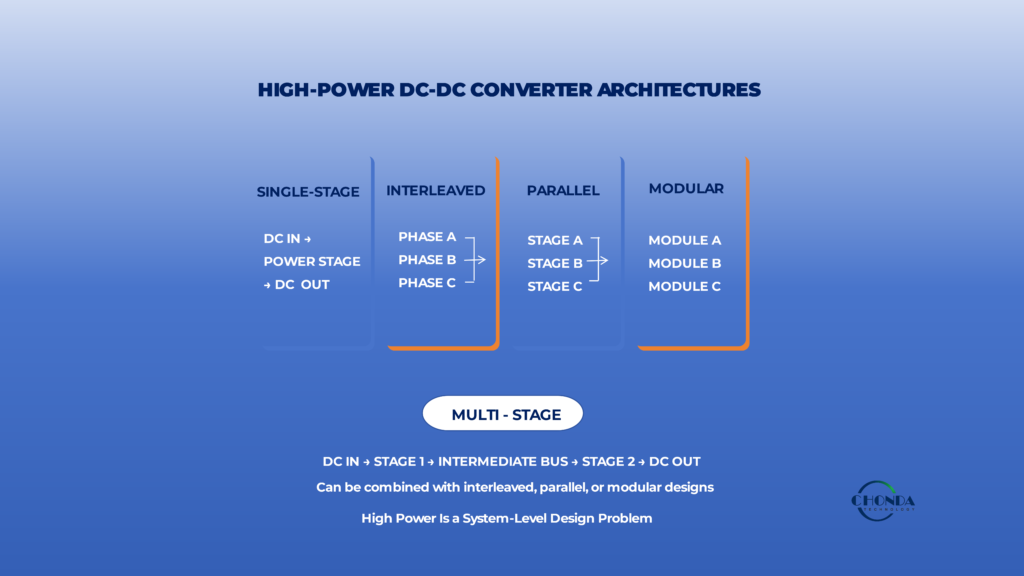
6. Converter Architecture for High-Power Applications
As the power level of a DC-DC converter increases, the architecture of the power stage can become just as important as the rating of the individual components.
A single conversion stage may be sufficient for a moderate-power application. At higher power, however, increasing current, switching loss, magnetic size, thermal density, and component stress can make a single-stage design less attractive.
Engineers may then consider architectures that divide the conversion task across multiple power paths.
The main approaches include:
Single-Stage
Multi-Stage
Interleaved
Parallel
Modular
These approaches are not necessarily mutually exclusive. A high-power converter may combine more than one of them depending on the application.
6.1 Single-Stage Conversion
The simplest architecture is:
DC Input → One Power-Conversion Stage → DC Output
A single-stage converter can offer a relatively direct power path with fewer active conversion stages and less system-level coordination.
For a well-defined application with one main output and a manageable power level, this simplicity can be valuable.
The challenge appears when the power level increases enough that current, thermal density, magnetic size, or switching stress become difficult to manage within one stage.
At that point, adding complexity may be justified if it allows the power burden to be distributed more effectively.
6.2 Multi-Stage Conversion
A multi-stage architecture divides the conversion function into more than one stage.
For example:
DC Input → Stage 1 → Intermediate DC Bus → Stage 2 → DC Output
This can be useful when the input-to-output conversion ratio is large or when different stages can be optimized for different functions.
One stage may focus on voltage conversion, while another provides tighter regulation or isolation.
The disadvantage is that every additional stage introduces its own losses and components.
Therefore:
More Stages → More Functional Flexibility
but also potentially:
More Stages → More Losses + More Control Complexity
The additional stage needs to solve a real system problem to justify its cost.
6.3 Interleaved Conversion
Interleaving uses multiple switching phases operating with controlled phase relationships.
For example:
Input → Phase A
Input → Phase B
Input → Phase C
The phases share the overall power requirement rather than forcing one switching path to carry the entire current.
This can provide several benefits in high-power applications.
Current can be distributed across multiple semiconductor paths, while input or output ripple can also be reduced depending on the architecture.
Interleaving can therefore improve current handling without requiring one power stage to process the full current alone.
6.4 Why Interleaving Becomes Attractive at Higher Power
Suppose a converter must deliver a large output current.
Instead of forcing one phase to carry the entire current, two or more interleaved phases can share the load.
The current per phase becomes lower, which can reduce the electrical and thermal burden on individual components.
The resulting architecture may also provide better utilization of magnetics and switching devices.
However, interleaving introduces additional control and current-balancing requirements.
The benefits therefore become most valuable when the increase in complexity is justified by the power level and operating requirements.
6.5 Parallel Power Stages
Parallel conversion uses multiple power stages that share the required output power.
A simplified architecture is:
DC Input
↓
Power Stage A ─┐
Power Stage B ─┼→ Common DC Output
Power Stage C ─┘
The main advantage is that the total power can be distributed across several conversion paths.
This can reduce the stress placed on each individual stage and can make higher power levels more practical.
The system may also gain redundancy or service flexibility depending on how the parallel stages are implemented.
The main engineering challenge is ensuring that the stages share current predictably.
Uneven current sharing can cause one stage to operate significantly harder than the others, reducing the expected thermal and reliability benefits.
6.6 Modular Architectures
A modular high-power converter takes the concept of distributed power one step further.
Instead of treating multiple power stages as parts of one tightly integrated converter, the architecture can use identifiable converter modules as building blocks.
For example:
DC Input
↓
Module A
Module B
Module C
↓
Common Output / Different Power Domains
Modules can be identical or can be optimized for different functions.
This can provide flexibility in system scaling, manufacturing, maintenance, and product variation.
However, modularization also adds interfaces, mechanical requirements, thermal coordination, and system-level control considerations.
The benefits are therefore strongest when the application genuinely benefits from modularity.
6.7 These Architectures Can Be Combined
In practical high-power systems, these architectural concepts can overlap.
For example, a converter may use:
Multi-Stage + Interleaved
or:
Parallel + Modular
or:
Multi-Stage + Isolated + Interleaved
A modular converter may contain several interleaved phases within each module.
The architecture should therefore be described in terms of the functions it performs rather than assuming that every design belongs to only one category.
6.8 Architecture Can Reduce the Burden on Individual Components
The key reason these architectures become attractive at higher power is that they can distribute electrical and thermal stress.
Instead of:
One Large Power Path
the system may use:
Several Smaller Controlled Power Paths
This can influence:
- Semiconductor current
- Magnetic component size
- Thermal density
- Switching frequency
- Current ripple
- Mechanical packaging
The result can be a converter that is easier to manage even if the overall system contains more components.
6.9 More Components Do Not Automatically Mean a Worse Converter
At first glance, adding phases, stages, or modules appears to make the system more complicated.
However, complexity should be evaluated relative to the problem being solved.
For example, using three power phases may add control circuitry and magnetic components, but it may also allow the system to operate at a practical current level with better thermal distribution.
The relevant question is therefore:
Does the additional architecture make the complete converter easier to operate within its electrical, thermal, mechanical, and reliability limits?
6.10 Architecture Selection Depends on the Application
A single-stage converter may remain the best solution when:
Power Is Moderate + Load Is Simple + Space Is Limited
A multi-stage architecture may become attractive when:
Conversion Ratio Is Large + Different Functions Need Separate Optimization
Interleaving may be valuable when:
Current Is High + Ripple Needs to Be Controlled + Multiple Phases Are Practical
Parallel stages may be useful when:
Total Power Is High + Current Sharing Can Be Controlled
Modular architecture may be appropriate when:
Scalability + Reuse + Multiple Power Domains are important.
These are design tendencies rather than universal rules.
6.11 A Practical High-Power Architecture Decision
A useful decision process is:
Define Power and Load Requirements
↓
Estimate Current and Loss
↓
Assess Thermal and Magnetic Limits
↓
Decide Whether One Stage Is Practical
↓
If Not, Consider Multi-Stage / Interleaved / Parallel / Modular Architecture
↓
Evaluate Added Losses and Integration Complexity
This prevents architecture from becoming more complicated simply because the available technology makes it possible.
6.12 The Practical Engineering Principle
As converter power increases, the architecture may need to evolve from:
One Power Stage Handling Everything
toward:
Multiple Controlled Power Paths Sharing the Conversion Burden
The purpose is not to maximize the number of stages, phases, or modules.
It is to distribute current, losses, thermal stress, magnetic requirements, and control complexity in a way that makes the complete converter practical.
The best high-power architecture is therefore the one that provides the required power and performance while keeping the electrical, thermal, mechanical, and control trade-offs within acceptable limits.
The next design question is how these distributed power paths affect overall power density, cooling requirements, and mechanical integration.
7. Power Density, Cooling, and Mechanical Integration
As the power level of a DC-DC converter increases, electrical design decisions increasingly become physical design decisions.
Higher current requires larger or more effective conductive paths.
Higher losses create more heat.
More heat requires a more capable thermal path.
And once the available cooling structure reaches its practical limit, the mechanical package can become one of the main constraints on further power scaling.
This creates a chain that is important in high-power converter design:
Electrical Stress → Power Loss → Heat Generation → Cooling Requirement → Mechanical Constraint
7.1 Power Density Is More Than a Size Metric
Power density is often expressed in terms such as watts per unit volume.
This is useful for comparing compact converter designs, but high power density also means that more electrical power and associated losses are being handled within a limited physical space.
For example, two converters may both deliver the same output power.
One may use a larger enclosure with relatively low thermal density.
The other may achieve a much smaller package while concentrating the same losses into a substantially smaller volume.
The second design may provide a better packaging result but create a more demanding thermal problem.
High power density should therefore be evaluated together with thermal density.
7.2 Higher Current Changes the Physical Structure
As explained earlier, increasing power often increases current.
That current must physically travel through:
Semiconductors → PCB / Bus Structure → Connectors → Magnetic Components → Load
At higher current, these paths may require larger conductors, thicker copper, parallel current paths, larger terminals, or different interconnection methods.
The electrical requirement therefore directly affects the physical package.
7.3 Cooling Requirements Grow with Absolute Power Loss
Even high efficiency can still produce substantial heat at high power.
For example, a converter delivering several kilowatts may dissipate hundreds of watts even when efficiency is in the mid-90% range.
That heat needs a continuous path out of the converter.
Depending on the application, this may require:
Natural Convection
Forced Air Cooling
Heat Spreaders
Liquid Cooling
or a combination of several methods.
The appropriate solution depends on power level, enclosure, ambient conditions, duty cycle, and required reliability.
7.4 Airflow Becomes a Mechanical Design Parameter
When forced-air cooling is used, thermal design begins to influence the mechanical arrangement directly.
The cooling system needs a defined airflow path.
Heat-generating components may need to be positioned so that the available airflow reaches them effectively.
For example:
Air Inlet → Hot Components → Heat Sink / Heat Exchanger → Air Outlet
If several high-loss components are placed close together, the air leaving the first hot region may already be warmer when it reaches the next component.
Component placement therefore affects the effective cooling capability of the complete converter.
7.5 Heat Sinks Also Consume Physical Volume
A larger heat sink can reduce component temperature, but it also takes space.
This creates a direct trade-off:
Higher Cooling Capacity
versus:
Lower Available Packaging Volume
The mechanical team may therefore need to reserve space for thermal structures before the final enclosure dimensions are fixed.
A converter that is electrically feasible may not be mechanically practical once the cooling requirement is included.
7.6 Magnetic Components Can Dominate the Package
In many high-power DC-DC converters, transformers and inductors are among the largest physical components.
Their size can be driven by:
- Power level
- Flux density
- Winding current
- Insulation
- Core loss
- Winding loss
- Thermal requirements
Trying to reduce magnetic volume can therefore create higher loss density and more difficult cooling.
Conversely, increasing magnetic size can improve thermal margin while reducing overall power density.
The magnetic design and mechanical package should therefore be considered together.
7.7 Mechanical Clearance Is Also an Electrical Requirement
High-power converters may carry substantial voltage in addition to substantial current.
The mechanical package must therefore provide enough space for:
- Creepage
- Clearance
- Isolation barriers
- Insulating structures
- Connector spacing
- Safe access
This can be particularly important when a compact converter is simultaneously trying to maximize both power density and high-voltage isolation.
Electrical safety can therefore establish a minimum physical size even before thermal requirements are considered.
7.8 Cooling and High-Voltage Insulation Can Compete
Thermal structures are often metallic because metals provide effective heat spreading.
High-voltage insulation, however, may require the same structure to remain electrically isolated from the power circuitry.
This creates a familiar design trade-off:
Thermal Conduction
versus:
Electrical Isolation
The solution may involve insulating thermal interfaces, isolated heat sinks, mechanical barriers, or alternative mounting structures.
The important point is that the cooling structure cannot be designed independently from the high-voltage insulation system.
7.9 Compact Packaging Can Increase Thermal Interaction
As components move closer together to improve power density, their thermal environments become more strongly coupled.
For example:
Switching Devices + Transformer + Rectification
may all generate heat within the same confined region.
Even if each component is acceptable under its individual thermal limit, the combined local environment may reduce the available thermal margin.
The mechanical layout should therefore account for both individual heat sources and their interaction.
7.10 Distributed Architectures Can Change the Mechanical Solution
A high-power system does not always need to place all power-processing functions inside one compact converter.
A distributed or modular architecture can separate functions physically.
For example:
Module A → Main Power
Module B → Auxiliary Power
Module C → Monitoring / Control
This can spread thermal sources and make cooling or service access easier.
The trade-off is that additional modules and interconnections consume more physical space.
The mechanical benefit therefore depends on how the complete equipment is organized.
7.11 Packaging Constraints Can Feed Back Into the Electrical Design
Mechanical design is not simply the final stage after the circuit has been completed.
For high-power converters, physical constraints can force changes in:
- Switching frequency
- Magnetic size
- Semiconductor selection
- Power-stage architecture
- Cooling method
- Module arrangement
For example, if the enclosure cannot accommodate the required magnetic volume, the engineering team may need to revisit the switching frequency or architecture.
Likewise, if airflow is insufficient, reducing loss may be preferable to simply increasing the heat sink.
Mechanical constraints can therefore feed back into the electrical design.
7.12 The Converter Should Be Designed as a Physical System
A high-power DC-DC converter should ultimately be viewed as:
Electrical System + Thermal System + Mechanical System
These three systems are closely linked.
A change that improves one may create a new limitation in another.
For example:
Higher Switching Frequency
→ Smaller Magnetics
but potentially:
→ Higher Switching Loss
→ More Heat
→ Greater Cooling Requirement
Similarly:
Larger Heat Sink
→ Better Cooling
but:
→ Larger Package
→ Lower Power Density
The engineering objective is therefore to find a balanced solution rather than optimize one dimension independently.
7.13 The Practical Engineering Principle
As power increases, the question changes from:
“Can the circuit handle the required power?”
to:
“Can the complete physical system handle the electrical and thermal consequences of that power within the available space?”
This means that power density, cooling, insulation, magnetic size, component placement, and mechanical integration should be considered together from the early design stages.
A high-power DC-DC converter is successful only when electrical capability, thermal capability, and mechanical implementation support the same power target.
The next step is to turn these design considerations into a practical selection process for engineers choosing a high-power DC-DC converter for a real application.
8. How to Select a High-Power DC-DC Converter
Selecting a high-power DC-DC converter requires more than matching the nominal input voltage, output voltage, and rated power.
As power increases, the electrical, thermal, magnetic, mechanical, and reliability requirements become increasingly interconnected.
A converter that appears suitable from its basic electrical specifications may still be difficult to use in the final equipment if its current capability, thermal conditions, power density, or cooling requirements do not match the application.
A practical selection process should therefore evaluate the converter as part of the complete power system.
8.1 Start With the Real Power Requirement
The first step is to define how much power the equipment actually needs.
This should include:
Continuous Power
Peak Power
Peak Duration
Duty Cycle
Expected Load Profile
For example, a system requiring 2kW continuously with a 2.5kW peak is fundamentally different from one that only reaches 2.5kW for a short transient.
The selected converter must be capable of meeting the continuous requirement under the real thermal conditions of the equipment, not simply the maximum number shown on a product label.
8.2 Define the Full Input and Output Envelope
The next step is to define the complete operating range.
On the input side:
Minimum Input → Nominal Input → Maximum Input → Transients
On the output side:
Minimum Load → Typical Load → Maximum Load → Peak Load
This is important because the converter may face very different electrical and thermal conditions at the extremes of the operating range.
A high-power converter should therefore be selected against the complete application envelope rather than a single nominal test point.
8.3 Evaluate Current, Not Just Power
At high power, current becomes a major selection criterion.
For a low-voltage output, even a relatively moderate power level can require substantial current.
For example:
1kW at 24V ≈ 41.7A
while:
2kW at 24V ≈ 83.3A
The converter therefore needs an output structure capable of handling the actual current continuously.
Engineers should consider:
- Output-current rating
- RMS current
- Peak current
- Current ripple
- Connection method
- PCB or bus-bar requirements
The nominal power rating alone does not provide enough information.
8.4 Check Efficiency at the Real Operating Point
A high-power converter can generate a significant amount of heat even when its efficiency appears excellent.
For example, a 5kW converter operating at 96% efficiency still dissipates approximately 200W.
The relevant question is therefore not only:
What is the maximum efficiency?
but:
What efficiency does the converter achieve where the equipment will actually operate most of the time?
This should include typical load, maximum continuous load, and relevant input-voltage conditions.
8.5 Evaluate the Thermal Environment
The next question is whether the converter can remove its losses under the actual installation conditions.
Consider:
Ambient Temperature
Cooling Method
Airflow
Mounting Structure
Enclosure
Continuous Operating Time
A converter that performs well on an open test bench may require derating inside a compact industrial enclosure.
For high-power applications, thermal compatibility should therefore be confirmed before treating the electrical rating as fully usable.
8.6 Check the Magnetic and Power-Density Implications
High-power conversion often involves substantial magnetic components.
The selected converter should therefore be evaluated for:
- Transformer or inductor size
- Power density
- Thermal density
- Winding requirements
- Mechanical volume
- Insulation structure
A compact converter can be attractive, but high power density may also mean greater thermal density.
The correct choice depends on whether the equipment prioritizes minimum size, maximum continuous power, lower thermal stress, or another system-level objective.
8.7 Evaluate the Architecture
High-power applications may be better served by different architectures.
Depending on the requirements, engineers may consider:
Single-Stage
Multi-Stage
Interleaved
Parallel
Modular
The selection should be based on the problem the architecture solves.
For example, interleaving may help distribute current and reduce ripple, while modularization may provide greater scalability and easier replacement.
Adding architectural complexity without a clear benefit can increase cost and integration effort.
8.8 Check Switching-Frequency Implications
The switching frequency should be considered together with the power level.
Higher frequency may reduce magnetic size, but it can also increase switching losses and thermal load.
At high power, these additional losses can become significant.
The selected converter should therefore provide a practical balance between:
Magnetic Size + Efficiency + Thermal Performance + EMI + Power Density
rather than maximizing frequency alone.
8.9 Review Protection and Operating Margin
A high-power converter should have adequate protection for the actual application.
The selection review should include:
- Input over-voltage / under-voltage
- Output over-current
- Short-circuit behavior
- Over-temperature protection
- Startup behavior
- Transient response
- Safe operating margin
Protection is particularly important at high power because fault conditions can involve substantial stored and delivered energy.
8.10 Consider Mechanical Integration Early
The converter should fit not only electrically but physically.
Before final selection, engineers should check:
Dimensions
Mounting
Connector Configuration
Cooling Interface
Clearance
Cable / Bus-Bar Access
Service Access
A converter that satisfies the electrical requirements but cannot be packaged or cooled efficiently may not be the right choice for the equipment.
8.11 Check Long-Term Operating Conditions
For industrial applications, high-power conversion may involve continuous operation for long periods.
The selection should therefore consider:
- Long-duration loading
- Thermal margin
- Ambient-temperature variation
- Cooling degradation
- Component aging
- Expected service life
The goal is not merely to keep the converter within its limits during a short test.
It is to maintain acceptable performance throughout the intended operating life.
8.12 Standard, Modular, or Customized?
Once the electrical, thermal, magnetic, and mechanical requirements are defined, engineers can decide whether a standard high-power converter is sufficient.
A standard solution is attractive when the requirements already match a proven product.
A modular solution may be more practical when the total power needs to be distributed across several conversion stages or when product scalability is important.
Customization becomes more attractive when the application combines unusual input ranges, output requirements, cooling conditions, mechanical constraints, or other requirements that standard products cannot satisfy efficiently.
8.13 A Practical Selection Sequence
A useful selection process is:
Power Requirement
↓
Input / Output Range
↓
Current
↓
Efficiency
↓
Thermal Environment
↓
Magnetic / Power Density
↓
Architecture
↓
Switching Frequency
↓
Protection / Margin
↓
Mechanical Integration
↓
Standard / Modular / Customized
This sequence helps prevent a common mistake: selecting a converter primarily from its headline power rating and only later discovering that its thermal or mechanical requirements do not fit the actual equipment.
8.14 The Right High-Power Converter Is a System Fit
The best high-power DC-DC converter is not necessarily the:
Highest-Power
or:
Highest-Efficiency
or:
Smallest
product available.
It is the converter that can deliver the required power continuously, within the real input and output ranges, while maintaining acceptable thermal performance, electrical margin, mechanical integration, and long-term reliability.
The practical principle is:
Select a high-power DC-DC converter for the conditions in which it will actually operate, not simply for the conditions stated in its headline specification.
9. Standard, Modular, or Customized High-Power Solutions
As DC-DC converter power increases, engineers may find that a standard converter no longer provides the best balance between electrical performance, thermal capability, mechanical integration, and development effort.
This does not mean that every high-power application requires a customized solution.
In many cases, a proven standard converter remains the most practical choice.
The important question is whether the available solution fits the complete application without forcing unnecessary compromises.
9.1 When a Standard High-Power Converter Is the Right Choice
A standard converter is often the best starting point when the application requirements already fall within an established product range.
For example, if the system has a clearly defined input range, output voltage, continuous power, isolation requirement, and acceptable mechanical format, a proven standard converter can reduce development time and simplify validation.
This approach is particularly attractive when the equipment will use the converter in a relatively conventional operating environment.
The goal is not to customize simply because the power level is high.
If an existing converter already provides the required performance, additional engineering work may provide little practical benefit.
9.2 When a Modular High-Power Architecture Makes Sense
A modular approach becomes more attractive when the total power or system structure makes one large conversion stage difficult to manage.
For example:
High-Power DC Bus
↓
Module A → Main Power
Module B → Auxiliary Power
Module C → Monitoring / Control
The modules can divide electrical and thermal stress while providing greater flexibility for product variations or future expansion.
Modularization may also allow engineers to use proven building blocks instead of developing one large converter for every product version.
However, the added modules and interfaces must still provide enough system-level value to justify their additional complexity.
9.3 When a Customized High-Power Converter Is Worth Considering
Customization becomes more valuable when several requirements cannot be matched efficiently by standard products.
For example, a high-power industrial application may require a combination of:
Wide Input Voltage Range
Specific Output Voltage
High Continuous Power
Defined Isolation
Restricted Installation Space
Special Cooling Conditions
Application-Specific Protection
A standard converter may satisfy several of these requirements while creating compromises in others.
If adapting the surrounding equipment would require major mechanical, thermal, or electrical changes, modifying the converter itself may become the more practical system-level solution.
9.4 Customization Does Not Always Mean a Completely New Design
A customized high-power solution can range from a limited modification to a more application-specific converter architecture.
Depending on the project, the required changes may involve:
- Input-voltage range
- Output voltage
- Power capability
- Isolation
- Protection behavior
- Cooling interface
- Mechanical dimensions
- Connector arrangement
- PCB configuration
The underlying conversion platform may still be based on a proven architecture.
This can reduce development risk while allowing the solution to fit the actual equipment more closely.
9.5 Avoid Solving a System Problem by Over-Customizing the Converter
Customization should not be used simply because the system has not yet been optimized.
For example, if a standard converter electrically satisfies the application but the enclosure cannot currently accommodate its cooling structure, changing the converter may not be the first solution.
The engineering team should first ask:
Is the converter unsuitable, or does the system need to be redesigned around the converter?
This distinction can prevent unnecessary development effort.
9.6 A Hybrid Approach Can Often Be More Practical
High-power systems can also combine standard modules with targeted customization.
For example:
Standard Power Module → Main Conversion
Standard Power Module → Auxiliary Power
Customized Module → Specialized High-Power Function
This approach can preserve the advantages of proven products while focusing engineering effort on the parts of the system that genuinely require a different solution.
The result may be a better balance between development time, performance, flexibility, and cost.
9.7 High Power Makes Application Context More Important
As power increases, the difference between a converter specification and the actual installation becomes more significant.
A high-power converter may need to operate inside a specific enclosure, under a defined cooling condition, with particular input and output interfaces.
The suitability of the converter should therefore be evaluated in the context of:
Electrical Requirements + Thermal Environment + Mechanical Constraints + Operating Profile
rather than from the product rating alone.
9.8 How CHONDA Can Fit High-Power Applications
CHONDA’s power-conversion solutions can be considered for industrial applications where high-voltage DC-DC conversion, defined output power, isolation, thermal integration, or application-specific mechanical requirements need to be addressed together.
Depending on the project, the appropriate approach may be a standard power module, a modified platform, a modular configuration, or a customized power solution.
For applications with unusual input ranges, output requirements, thermal conditions, or mechanical constraints, the converter can be evaluated together with the complete power architecture rather than as an isolated product.
The objective is to identify the solution that fits the actual application with the appropriate level of engineering customization.
9.9 A Practical Decision Framework
A useful decision process is:
Requirements Match a Standard Solution
→ Choose the proven standard platform.
Power or Functional Requirements Benefit from Distributed Conversion
→ Consider a modular architecture.
Important Electrical or Mechanical Requirements Fall Outside Standard Solutions
→ Consider a customized solution.
The Application Is Highly Specialized
→ Evaluate the complete power architecture before deciding how much customization is justified.
The right answer depends on the system rather than on the product category alone.
9.10 The Goal Is the Right Level of Engineering
High-power conversion does not automatically require a custom converter.
Likewise, standard products should not be forced into an application where they create significant compromises.
The most practical approach is to use proven solutions wherever they fit and apply additional engineering only where it creates meaningful system value.
For high-power DC-DC applications, the goal is therefore:
Standardization Where Possible + Modularity Where Useful + Customization Where Necessary
This provides a practical path toward a converter architecture that can meet the required power, thermal, mechanical, and reliability objectives without adding unnecessary complexity.
10. Common High-Power DC-DC Design Mistakes
High-power DC-DC converter problems are often caused not by one incorrect component, but by an incomplete view of the complete power system.
Before finalizing a high-power design, it is useful to check a few common assumptions.
10.1 Selecting by Power Rating Alone
A converter may have the required power rating and still be unsuitable for the application.
Input range, output current, thermal conditions, cooling, duty cycle, and mechanical integration all affect the practical usable power.
10.2 Ignoring Current at the Low-Voltage Output
High output power at a low voltage can require very large current.
For example, a 2kW output at 24V requires more than 80A.
PCB copper, connectors, bus structures, magnetic components, and cables must all be capable of carrying that current continuously.
10.3 Treating Peak Power as Continuous Power
A converter that can tolerate a short-duration power peak is not necessarily suitable for continuous operation at the same level.
Peak magnitude, duration, repetition rate, and thermal recovery should all be considered.
10.4 Focusing Only on Efficiency Percentage
A small percentage of loss can represent a large amount of heat at high power.
For example, even 4% loss in a 5kW converter represents approximately 200W of heat.
The actual thermal environment should therefore be evaluated using absolute power loss as well as efficiency.
10.5 Scaling a Low-Power Design Without Reconsidering the Architecture
Simply increasing component ratings does not always produce a practical high-power converter.
Higher power may require:
- Interleaving
- Parallel power stages
- Multi-stage conversion
- Modular architecture
The preferred architecture should be reconsidered when current, thermal density, or magnetic size becomes difficult to manage.
10.6 Increasing Switching Frequency Only to Reduce Size
Higher frequency can reduce magnetic size, but it can also increase switching losses, thermal load, and EMI.
The frequency should therefore be selected as part of the overall efficiency, thermal, magnetic, and power-density trade-off.
10.7 Designing Thermal Performance After the Electrical Design
At high power, thermal capability can determine the practical continuous power of the converter.
Cooling, heat spreading, component placement, and enclosure conditions should therefore be considered early rather than added after the power stage is complete.
10.8 Ignoring the Final Mechanical Environment
A converter that performs well on a laboratory bench may behave differently inside a compact industrial enclosure.
Ambient temperature, airflow, mounting structure, cable routing, and nearby heat sources can all change the practical operating conditions.
10.9 Choosing Customization Before Defining the Real Problem
A custom converter is not automatically better.
Engineers should first determine whether the issue can be solved through system integration, module selection, or architecture changes before committing to a customized design.
10.10 The Final Check
Before approving a high-power DC-DC converter, ask:
Can every part of the electrical, thermal, magnetic, mechanical, and protection system support the required power continuously under the real operating conditions?
If the answer is clear, the design is much more likely to remain reliable after it moves from the laboratory into the actual equipment.
The practical principle is:
High-power conversion is a system-design problem, not simply a higher-rated version of a lower-power converter.
Conclusion
High-power DC-DC conversion is not simply a matter of increasing the rated power of a lower-power converter.
As power increases, current, electrical stress, power loss, thermal density, magnetic requirements, switching behavior, power density, cooling, and mechanical integration become increasingly interconnected.
A practical high-power design therefore needs to consider the complete chain:
Power Requirement → Current → Electrical Stress → Losses → Thermal Load → Magnetics → Architecture → Cooling → Mechanical Integration
At higher power levels, the preferred architecture may also change.
A single-stage converter may remain appropriate for a relatively straightforward application, while interleaved, parallel, multi-stage, or modular architectures may become more practical when current, thermal, magnetic, or scalability constraints become difficult to manage in one power stage.
The same principle applies to converter selection.
The highest power rating, highest peak efficiency, or smallest package is not automatically the best solution.
The more important question is whether the converter can deliver the required continuous and peak power under the actual input, load, thermal, mechanical, and environmental conditions of the application.
For industrial equipment, the best high-power DC-DC converter is therefore one that provides an appropriate balance of:
Electrical Capability + Efficiency + Thermal Margin + Power Density + Reliability + Integration Practicality
High-power conversion should ultimately be treated as a system-design problem rather than simply a higher-rated version of a lower-power converter.
Related Articles
How to Select a High Voltage DC-DC Converter Module for Industrial Applications
Explore the key electrical, thermal, isolation, and mechanical parameters used to select high-voltage DC-DC converter modules.
DC-DC Converter Selection Guide: Key Parameters for High Voltage Applications
Review the main parameters engineers should evaluate when selecting a DC-DC converter for a high-voltage industrial application.
High Voltage Power Supply Design Guide
Understand a system-level approach to high-voltage power architecture, including conversion stages, isolation, regulation, EMI, thermal management, protection, and power-module selection.
High Voltage DC to Low Voltage DC Converter Design & Selection
Explore HV-to-LV conversion architectures, isolation, output regulation, protection, thermal considerations, and converter selection.
High Frequency DC-DC Converter Design: Efficiency & EMI
Learn how switching frequency affects magnetic size, switching losses, EMI, thermal performance, and power density.
Modular High Voltage DC-DC Converters: Benefits & Applications
Explore modular power-conversion architectures and how multiple DC-DC modules can distribute power and thermal loads across different power domains.