We help the world since 2012

Isolation Transformer vs Isolated DC-DC Converter: Which Is Right for Your Application?
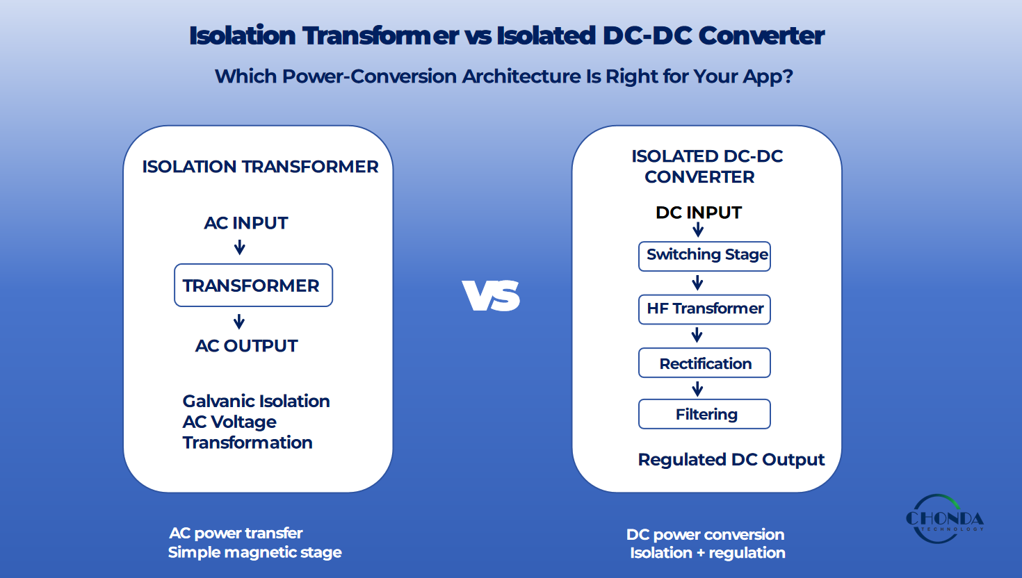
When an industrial system requires electrical isolation between the input and output, engineers may consider either an isolation transformer or an isolated DC-DC converter.
Although both solutions can provide galvanic isolation, they are not interchangeable in every application.
An isolation transformer primarily transfers AC power between electrically separated windings. An isolated DC-DC converter, on the other hand, combines switching electronics, magnetic components, rectification, filtering, and control functions to convert one DC voltage into another while maintaining electrical isolation.
The right choice depends on the input and output requirements, voltage conversion ratio, power level, regulation requirements, efficiency, available space, noise considerations, and system architecture.
1. What Is an Isolation Transformer?
An isolation transformer is a magnetic component with electrically separated primary and secondary windings.
Energy is transferred between the windings through a magnetic field rather than through a direct conductive connection.
The primary and secondary sides can therefore remain galvanically isolated while AC power is transferred from one side to the other.
An isolation transformer can be used when the primary design objective is:
- Galvanic isolation
- Electrical separation between circuits
- Voltage transformation
- Noise reduction in selected applications
- Isolation of sensitive equipment from a power source
A transformer does not, by itself, provide DC voltage regulation or DC-to-DC conversion.
For applications requiring regulated DC output, additional rectification, filtering, regulation, or power-conversion circuitry may be required.
2. What Is an Isolated DC-DC Converter?
An isolated DC-DC converter is a complete power-conversion system that converts one DC voltage into another while maintaining galvanic isolation between the input and output sides.
Unlike a standalone isolation transformer, an isolated DC-DC converter combines isolation with switching, voltage conversion, rectification, filtering, and control functions. A typical isolated converter uses a high-frequency transformer to transfer energy across the isolation barrier while the switching stage controls how power is delivered to the output.
A typical isolated DC-DC converter may include:
- Switching devices
- A high-frequency isolation transformer
- Rectification and output filtering
- Feedback and control circuitry
- Protection functions
Because the conversion process is actively controlled, an isolated DC-DC converter can be designed to provide a regulated DC output over a specified input-voltage range.
This makes isolated DC-DC converters particularly useful when a system requires both galvanic isolation and controlled DC voltage conversion.
Typical applications include:
- PV monitoring systems
- Solar combiner box monitoring
- Industrial automation
- Robotics and embedded systems
- Battery energy storage systems
- Isolated measurement and control circuits
- Industrial communication equipment
For high-voltage applications, the converter design must also consider isolation requirements, creepage and clearance, switching noise, thermal performance, and PCB layout.
An isolated DC-DC converter is therefore not simply an isolation component. It is a complete power-conversion architecture in which electrical isolation is integrated into the DC-DC conversion process.
3. Isolation Transformer vs Isolated DC-DC Converter
The most important difference is their role in the power system.
An isolation transformer is primarily a magnetic isolation and voltage-transformation component for AC power.
An isolated DC-DC converter is a complete DC power-conversion system that incorporates isolation into the conversion process.
| Feature | Isolation Transformer | Isolated DC-DC Converter |
|---|---|---|
| Input | AC | DC |
| Output | AC | DC |
| Galvanic isolation | Yes | Yes, when designed as an isolated topology |
| Voltage conversion | AC voltage ratio | DC voltage conversion |
| Voltage regulation | Requires additional circuitry | Usually integrated into the converter design |
| Switching electronics | No | Yes |
| High-frequency operation | Not necessarily | Common |
| Power density | Depends on transformer design and frequency | Often higher for compact switching designs |
| Control functions | External | Often integrated |
| Protection functions | Usually external | Can be integrated |
| Typical role | Isolation and AC voltage transformation | Isolated DC power conversion |
The table provides a general engineering comparison. Actual performance depends on the specific topology, transformer construction, switching frequency, power rating, control method, and system requirements.
4. When Should You Use an Isolation Transformer?
An isolation transformer can be a practical choice when the system already operates with AC power and the primary requirement is electrical separation, AC voltage transformation, or both.
In these situations, using a transformer can provide the required isolation without introducing a complete switching-based DC power-conversion stage.
4.1. AC Input and AC Output
If the application requires AC power on both sides of the isolation barrier, an isolation transformer can provide the required electrical separation while transferring AC energy through magnetic coupling.
This approach is commonly used when the system does not require DC output regulation at the isolation stage.
4.2. Simple Power Architecture
For applications where voltage regulation and DC conversion are not required at the isolation stage, a transformer can provide a relatively straightforward power architecture.
The transformer can perform the required AC voltage transformation while keeping the primary and secondary circuits electrically isolated. Additional power-conversion stages can then be added elsewhere in the system when needed.
4.3. Higher-Power AC Applications
Transformers are widely used in industrial power systems where AC power must be transferred between electrically separated circuits.
For higher-power AC applications, transformer-based architectures can provide a practical way to achieve electrical isolation and voltage transformation without requiring high-frequency switching electronics in the isolation stage.
The appropriate transformer construction, winding configuration, insulation system, and thermal design still depend on the required voltage, power level, operating frequency, and application environment.
4.4. Specific Noise and Grounding Requirements
Galvanic isolation can help prevent direct conductive current paths between two circuits, which may be useful when managing grounding interactions between separate parts of a system.
However, isolation alone does not automatically guarantee low noise.
Actual common-mode noise performance depends on factors such as transformer construction, parasitic capacitance between windings, shielding, grounding strategy, and the rest of the system.
For noise-sensitive applications, these factors should therefore be considered as part of the complete system design rather than treating the transformer as an isolated solution by itself.
5. When Should You Use an Isolated DC-DC Converter?
An isolated DC-DC converter becomes a practical choice when a system starts with DC power and requires a regulated DC output while maintaining electrical isolation between the input and output sides.
Compared with a standalone isolation transformer, an isolated DC-DC converter can integrate voltage conversion, regulation, isolation, filtering, and protection into a single power-conversion architecture.
5.1. High-Voltage DC Input and Low-Voltage DC Output
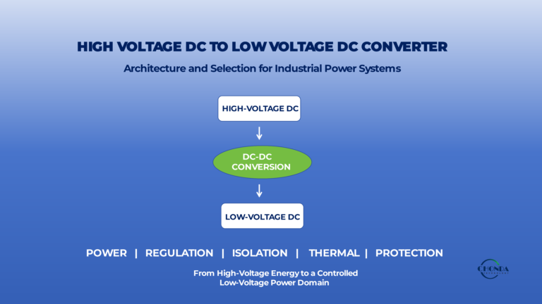
An isolated DC-DC converter is particularly useful when a low-voltage electronic circuit must be powered from a much higher-voltage DC bus.
For example, a monitoring unit may need a stable 24VDC auxiliary supply while the available power source is a high-voltage DC bus.
In this type of application, an isolated DC-DC converter can provide both the required voltage conversion and galvanic isolation.
5.2. Regulated DC Output
When downstream electronics require a stable DC supply, an isolated DC-DC converter can provide closed-loop voltage regulation as part of the overall converter design.
This can be especially important for:
- Monitoring electronics
- Control circuits
- Communication interfaces
- Sensors
- Embedded processors
The actual regulation performance depends on the converter topology, control method, input range, load conditions, and output requirements.
5.3. Wide Input Voltage Range
Some industrial systems operate over a relatively wide DC input-voltage range.
An isolated DC-DC converter can be designed to accept a specified input range while maintaining the required output voltage.
This is particularly relevant to applications such as:
- PV monitoring systems
- Solar combiner box monitoring
- Battery energy storage systems
- Industrial control systems
For example, a converter designed for a high-voltage DC bus may be required to operate over a defined input range rather than from a single fixed voltage.
5.4. Integrated Power Functions
An isolated DC-DC converter can combine several power-management functions within one architecture, including:
- Voltage conversion
- Galvanic isolation
- Output regulation
- Filtering
- Over-voltage protection
- Over-current or short-circuit protection
This can reduce the need for multiple separate power stages and simplify system integration.
5. Compact and Application-Specific Designs
High-frequency switching can allow the magnetic components used in isolated DC-DC converters to be smaller than conventional low-frequency transformer solutions for comparable power levels.
This can be useful when PCB space, equipment size, and power density are important design constraints.
However, higher switching frequency also introduces additional considerations, including EMI, thermal management, transformer design, and PCB layout.
6. Typical Applications
Isolated DC-DC converters are commonly considered for applications such as:
- PV monitoring systems
- Solar combiner box monitoring
- Battery energy storage systems
- Industrial automation
- Robotics and embedded systems
- Industrial control systems
- Isolated measurement circuits
- Communication equipment
- Specialized industrial power supplies
The most suitable converter depends on the required input range, output voltage and current, isolation level, power rating, efficiency, thermal conditions, and application environment.
7. Efficiency and Power Density
Efficiency and power density are important factors when choosing between transformer-based and switching-based power solutions.
An isolated DC-DC converter typically operates at a much higher switching frequency than a conventional line-frequency transformer. Higher switching frequency allows the magnetic components, particularly transformers and inductors, to be designed with smaller physical dimensions for a given power level.
This can help reduce the size and weight of the overall power-conversion stage and is one reason why high-frequency switching converters are widely used in compact industrial and embedded power systems.
However, increasing switching frequency does not automatically improve overall efficiency.
Higher switching frequencies can increase several types of loss, including:
- Switching losses in semiconductor devices
- Transformer and winding losses
- Magnetic core losses
- Conduction losses
- Gate-drive losses
Engineers must also consider:
- Thermal management
- EMI and electromagnetic compatibility
- PCB layout
- Parasitic capacitance and inductance
- Transformer construction
- Cooling conditions
For example, reducing the size of a magnetic component may improve power density but can also increase thermal stress or magnetic losses if the design is not optimized for the operating frequency and power level.
Therefore, smaller does not automatically mean better.
A practical design should balance efficiency, power density, thermal performance, EMI, reliability, and cost according to the complete system requirements.
For industrial applications, the best solution is usually the one that provides the required electrical performance within the available mechanical, thermal, and regulatory constraints.
8. Isolation Does Not Automatically Mean Low Noise
Both isolation transformers and isolated DC-DC converters can provide galvanic isolation between two electrical circuits. However, galvanic isolation alone does not guarantee low EMI or low noise.
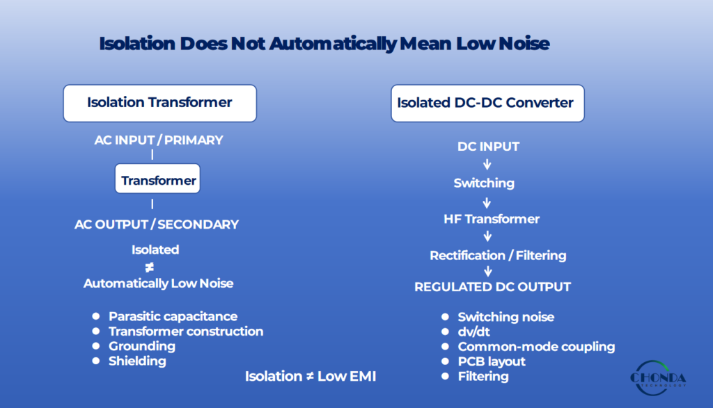
In an isolated DC-DC converter, high-frequency switching and the rapid voltage transitions associated with the power stage can create several types of noise, including:
- Common-mode noise
- Differential-mode noise
- Fast voltage transitions
- Magnetic coupling
- Capacitive coupling across the isolation barrier
These effects can become particularly important in systems that contain sensitive measurement, communication, control, or monitoring electronics.
For this reason, EMI performance should be considered as part of the complete power-system design. Important factors may include:
- PCB layout
- Switching-loop area
- Transformer construction
- Parasitic capacitance
- Grounding and return paths
- Shielding
- Input and output filtering
- Switching frequency and edge rates
For high-voltage applications, engineers should also consider creepage, clearance, insulation systems, and the required isolation level during the design stage.
An isolation barrier should therefore not be treated as a standalone solution for noise control. A well-designed isolated converter manages isolation, switching behavior, PCB layout, grounding, filtering, and magnetic construction together to achieve the required system-level EMI performance.
In practical applications, the best results usually come from controlling noise at its source rather than relying only on filters after unwanted noise has already propagated through the system.
9. Isolation Transformer vs Isolated DC-DC Converter: Key Selection Factors
Before selecting a solution, engineers should evaluate the complete power-conversion requirements rather than focusing on isolation alone.
Several factors can help determine which architecture is more appropriate.
9.1. What Is the Input Voltage?
The first question is whether the available power source is AC or DC.
If the system operates from an AC source and requires electrical separation or AC voltage transformation, an isolation transformer may be a straightforward solution.
If the source is a high-voltage DC bus, an isolated DC-DC converter is often more suitable because it can combine DC voltage conversion with galvanic isolation.
9.2. What Is the Required Output?
The required output type also strongly influences the architecture.
Does the system require AC on the secondary side, or does downstream equipment require a regulated DC supply?
An isolation transformer can transfer and transform AC power, while an isolated DC-DC converter can provide a controlled DC output as part of the conversion process.
9.3. Is Voltage Conversion Required?
Both solutions can transform voltage, but they do so in different ways.
An isolation transformer provides an AC voltage ratio determined primarily by its winding configuration and turns ratio.
An isolated DC-DC converter can provide controlled DC voltage conversion over a specified input-voltage range, typically using switching devices, a high-frequency transformer, rectification, filtering, and feedback control.
9.4. How Much Power Is Required?
The required power level affects the overall architecture and component selection.
Engineers may need to consider:
- Transformer or magnetic component size
- Semiconductor ratings
- Thermal performance
- PCB area
- Cooling requirements
- Efficiency
- Mechanical constraints
A solution that works well at one power level may not be the most practical choice at another.
9.5. How Important Are Size and Power Density?
When equipment space is limited, power density can become an important design factor.
High-frequency isolated DC-DC converters can use smaller magnetic components than conventional low-frequency transformer solutions for comparable power levels.
However, the resulting design must still satisfy thermal, EMI, insulation, and reliability requirements.
Compact size should therefore be evaluated together with the complete system performance.
9.6. What Isolation Level Is Required?
Isolation requirements should be evaluated together with the actual operating conditions of the system.
Engineers should consider:
- Working voltage
- Transient conditions
- Creepage distance
- Clearance distance
- Insulation system
- Pollution environment
- Applicable safety standards
- Required isolation rating
For high-voltage applications, insulation should be treated as a complete system requirement rather than simply selecting a component with a specified isolation voltage.
9.7. How Sensitive Is the System to EMI?
EMI requirements become especially important when the system contains precision measurement, communication, monitoring, or control electronics.
An isolated DC-DC converter introduces high-frequency switching, so engineers should consider:
- Switching noise
- Common-mode coupling
- Differential-mode noise
- PCB layout
- Grounding
- Filtering
- Transformer parasitics
These factors should be considered during the initial power-architecture stage rather than addressed only after the prototype has been built.
10. A Practical Decision Guide
A useful way to approach the selection is to start with the power source and required output.
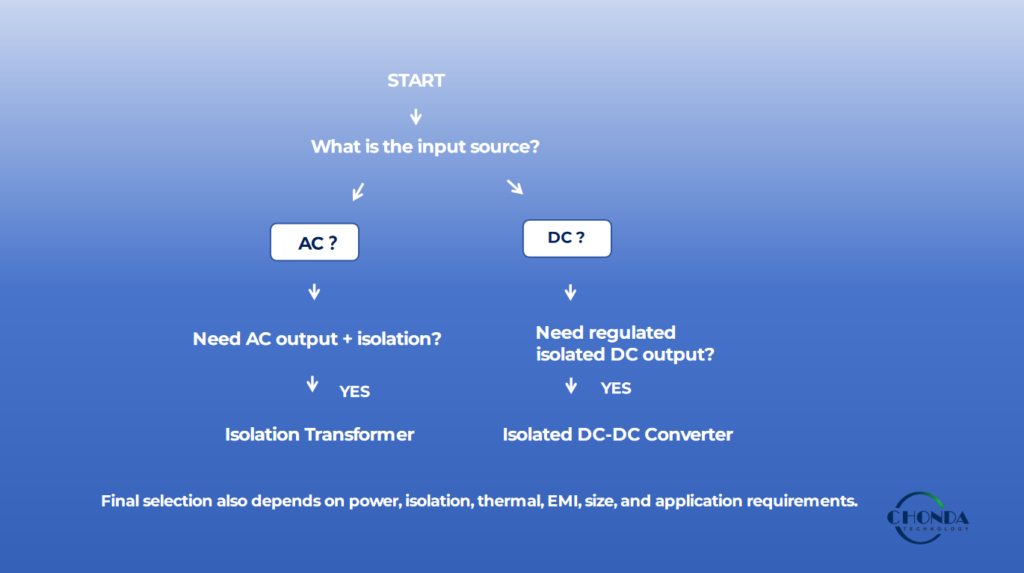
10.1 Choose an Isolation Transformer When:
- The system operates from AC power.
- Electrical separation is a primary requirement.
- AC voltage transformation is required.
- A relatively simple magnetic power-transfer architecture is appropriate.
- Regulated DC output is not required directly from the transformer.
10.2. Consider an Isolated DC-DC Converter When:
- The input source is DC.
- A regulated DC output is required.
- A defined or wide DC input range must be accommodated.
- Compact size or high power density is important.
- Isolation, voltage conversion, regulation, and protection need to be integrated into one power-conversion stage.
In many industrial systems, the decision is not simply between a “transformer” and a “DC-DC converter.”
The more useful question is:
Which power-conversion architecture best matches the electrical, mechanical, isolation, thermal, EMI, and application requirements of the system?
The answer should come from the complete system requirements rather than from a single specification such as input voltage, power rating, or isolation voltage.
11. How CHONDA Supports Industrial Power Applications
CHONDA provides transformer and power-module solutions for a wide range of industrial power requirements, from conventional AC isolation to high-voltage DC power conversion.
Our product portfolio includes:
- Toroidal transformers
- Audio and isolation transformers
- AC-DC power modules
- Isolated DC-DC power modules
- High-voltage DC-DC converters
- Customized power solutions
The appropriate solution depends on the complete system requirements, including input voltage, output requirements, isolation level, power rating, installation environment, thermal conditions, and overall power architecture.
For applications that require AC isolation or voltage transformation, a transformer-based solution may be appropriate. For systems that require isolated and regulated DC power from a DC source, an isolated DC-DC converter may provide a more integrated solution.
Our engineering team works with customers to understand their electrical and application requirements and identify a suitable standard or customized power solution.
12. Conclusion
An isolation transformer and an isolated DC-DC converter can both provide galvanic isolation, but they address different power-conversion requirements.
An isolation transformer is primarily a magnetic component for transferring and transforming AC power while maintaining electrical separation between circuits. An isolated DC-DC converter combines galvanic isolation with DC voltage conversion, regulation, filtering, and other power-management functions.
The right choice depends on the complete application requirements, including the input and output type, required regulation, power level, isolation requirements, size, thermal conditions, EMI performance, and system architecture.
For engineers working with industrial automation, PV monitoring, energy storage, robotics, embedded electronics, and other demanding applications, understanding the difference between these two architectures can help simplify system design and improve long-term power-system reliability.
CHONDA supports both transformer-based and power-module solutions, including customized designs for application-specific requirements.
Related Articles
1. What Is a High Voltage DC-DC Converter?
Learn the basic principles, architecture, and applications of high-voltage DC-DC converters for industrial power systems.
2. High Voltage DC-DC Converter Isolation Design: Principles and Applications
Explore isolation architecture, insulation requirements, and key design considerations for high-voltage DC-DC converters.
3. High Voltage DC-DC Converter EMI Design Considerations
Understand switching noise, common-mode coupling, filtering, grounding, and other EMI considerations in high-voltage DC-DC converter design.
4. High Voltage DC-DC Converter PCB Design Considerations
Learn how creepage, clearance, PCB layout, grounding, switching nodes, and return paths affect high-voltage DC-DC converter reliability.
5. How to Select the Right High Voltage DC-DC Converter
Review the key parameters engineers should evaluate when selecting a high-voltage DC-DC converter for a specific application.