We help the world since 2012
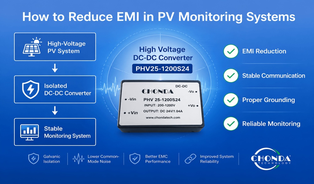
How to Reduce EMI in PV Monitoring Systems
Photovoltaic monitoring systems often operate in electrically noisy environments where high-voltage DC cables, switching power converters, inverters, and communication networks are installed in close proximity. Without proper electromagnetic interference (EMI) control, monitoring equipment may experience communication errors, unstable sensor readings, or unexpected system interruptions.
Reducing EMI requires more than adding filters after problems appear. Proper power supply selection, cable routing, grounding strategy, shielding, and electrical isolation should all be considered during system design. By addressing these factors early, engineers can significantly improve the reliability of PLCs, RTUs, RS485 networks, and other monitoring devices.
This article explains the common sources of EMI in PV monitoring systems and introduces practical design methods to minimize interference while maintaining stable long-term operation.
What Is EMI in PV Monitoring Systems?
Electromagnetic interference (EMI) refers to unwanted electrical energy that disrupts the normal operation of electronic equipment. In photovoltaic (PV) monitoring systems, EMI is commonly generated by high-frequency switching devices, long high-voltage DC cables, inverters, and nearby power electronics. If not properly controlled, electromagnetic interference can affect both power quality and communication stability.
Unlike general electrical noise, EMI is caused by electromagnetic fields that can be transmitted through cables, circuit boards, or even through the air. In a typical PV monitoring installation, sensitive devices such as PLCs, RTUs, RS485 communication modules, sensors, and data loggers may all be exposed to these interference sources.
As PV systems continue to increase in voltage and size, the possibility of EMI also increases. Modern photovoltaic monitoring systems operating with 1000VDC or 1500VDC PV strings require careful electromagnetic compatibility (EMC) design to ensure reliable long-term operation.
Typical symptoms of EMI include:
- Intermittent RS485 communication failures
- Unstable sensor measurements
- Random PLC or RTU resets
- Data transmission errors
- Unexpected monitoring alarms
Understanding how EMI is generated is the first step toward selecting appropriate power supplies, cable routing methods, shielding techniques, and isolation solutions that improve overall system reliability.
Common Sources of EMI
Electromagnetic interference in PV monitoring systems may originate from multiple sources within the electrical installation. Identifying these interference sources helps engineers select appropriate mitigation methods during system design.
DC-DC Converters and Switching Power Supplies
High-voltage DC-DC converters and other switching power supplies operate by rapidly switching semiconductor devices at high frequencies. These switching transitions generate electromagnetic energy that may couple into nearby power lines or communication circuits if filtering and isolation are not properly implemented.
Solar Inverters
PV inverters are among the largest sources of EMI in photovoltaic systems. Their high-frequency switching operation, combined with high output power, can produce both conducted and radiated electromagnetic interference that affects nearby monitoring equipment and communication networks.
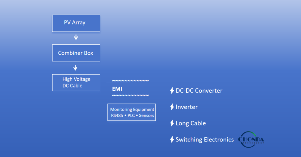
Long High-Voltage DC Cables
Photovoltaic strings often require long cable runs between PV arrays, combiner boxes, and inverters. These cables may act as antennas, allowing electromagnetic energy to be transmitted over long distances. Poor cable routing can further increase coupling between power cables and low-voltage signal cables.
Communication Cables
RS485, Ethernet, and other communication cables may pick up interference when routed close to high-voltage conductors or switching equipment. Without adequate shielding or proper cable separation, communication quality may gradually degrade, resulting in intermittent data transmission errors.
Improper Grounding and Equipment Layout
Ground loops, inadequate grounding, and poor equipment layout can significantly increase system susceptibility to EMI. Placing communication cables parallel to high-voltage DC cables or routing signal wiring close to switching devices creates additional opportunities for electromagnetic coupling and unstable system operation.
Practical Methods to Reduce EMI
Effective EMI control should be considered during the system design stage rather than after installation. In most PV monitoring applications, electromagnetic interference can be significantly reduced through proper wiring, equipment selection, grounding, and electrical isolation. The following practices are widely adopted in industrial photovoltaic systems.
Separate Power and Signal Cables
High-voltage DC cables should be routed separately from communication and sensor cables whenever possible. Running power cables and RS485 or sensor wiring in parallel over long distances increases electromagnetic coupling and makes communication circuits more susceptible to interference.
When cable crossings are unavoidable, they should intersect at approximately 90 degrees instead of running side by side. This simple routing practice helps minimize induced noise and improves overall communication stability.
Use Shielded Communication Cables
Communication networks such as RS485 should use shielded twisted-pair cables, particularly in installations with long cable runs or electrically noisy environments. Proper shielding reduces radiated interference and helps maintain signal integrity.
To achieve the best performance, cable shields should be grounded according to the system design requirements. Incorrect shield termination may reduce the effectiveness of the shielding or even introduce additional interference.
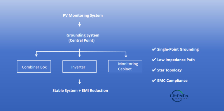
Implement Proper Grounding
A reliable grounding system provides a stable electrical reference and helps suppress common-mode interference. Grounding should be carefully planned to avoid unnecessary ground loops while maintaining effective equipment protection.
Monitoring equipment, communication devices, and power supplies should all follow the project’s grounding strategy rather than being connected independently at random locations.
Install EMI Filters When Necessary
In systems with particularly high switching activity or severe electromagnetic environments, additional EMI filters may be installed at the input or output of power conversion equipment.
Appropriate filtering helps reduce conducted interference before it propagates through the power distribution network. The filter specifications should always match the operating voltage, current, and switching characteristics of the application.
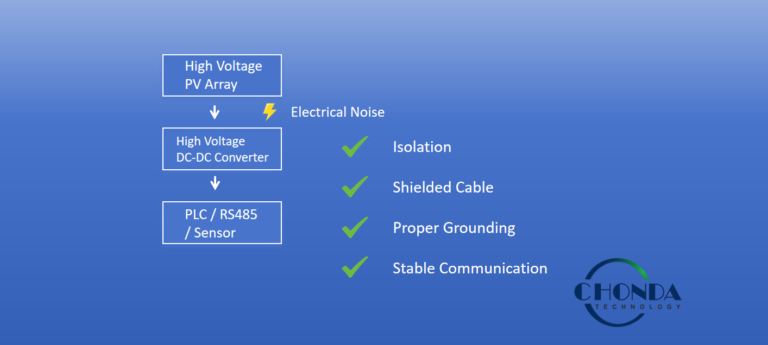
Select an Isolated Power Supply
An isolated high-voltage DC-DC converter provides galvanic isolation between the high-voltage PV bus and the low-voltage monitoring circuit. This isolation blocks common-mode noise from propagating into PLCs, RTUs, sensors, and communication interfaces.
Compared with non-isolated solutions, isolated converters generally provide better EMC performance while improving electrical safety and long-term system reliability.
Why Isolated DC-DC Converters Help Reduce EMI
Among the various EMI mitigation methods, electrical isolation is one of the most effective approaches for improving signal quality in PV monitoring systems.
An isolated high-voltage DC-DC converter creates a galvanic isolation barrier between the photovoltaic DC bus and the low-voltage monitoring circuit. Instead of allowing electrical noise to propagate directly through the power supply, the isolation barrier significantly reduces common-mode interference reaching sensitive electronic equipment.
For communication devices such as PLCs, RTUs, RS485 interfaces, and data loggers, this means cleaner supply voltage, improved signal integrity, and fewer communication errors under electrically noisy operating conditions.
Compared with non-isolated power supplies, isolated converters typically provide several practical advantages in photovoltaic monitoring applications:
- Lower common-mode noise
- Improved communication stability
- Better EMC performance
- Reduced risk of communication interruptions
- Higher long-term system reliability
For medium- and high-voltage photovoltaic installations, selecting an isolated DC-DC converter is often one of the simplest ways to improve overall monitoring performance while minimizing EMI-related issues.
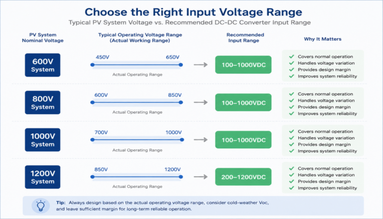
For applications requiring wide-input high-voltage isolated power conversion, our High Voltage DC-DC Converter Modules support input ranges from 100–1000VDC and 200–1200VDC, making them suitable for combiner boxes, monitoring units, RTUs, PLCs, and other photovoltaic monitoring equipment.
👉 Explore our High Voltage DC-DC Converter Modules
Recommended High Voltage DC-DC Converter
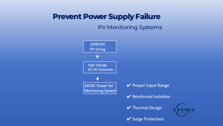
Photovoltaic monitoring systems often operate directly from high-voltage PV strings, making power supply selection an important part of EMC design. A high-voltage isolated DC-DC converter not only provides reliable low-voltage power but also helps reduce common-mode noise and improve communication stability.
For PV monitoring applications, engineers should consider the following features when selecting a DC-DC converter:
- Wide input voltage range for PV string applications
- Reinforced isolation to suppress electrical interference
- Stable output voltage for monitoring electronics
- Industrial-grade reliability for outdoor operation
- Compact design for combiner boxes and monitoring cabinets
CHONDA’s High Voltage DC-DC Converter Modules are specifically designed for photovoltaic monitoring systems, supporting input voltage ranges of 100–1000VDC and 200–1200VDC. These converters are widely used to power PLCs, RTUs, data loggers, communication modules, and other monitoring equipment while helping improve EMC performance and long-term system reliability.
👉 Explore our High Voltage DC-DC Converter Modules
Conclusion
Electromagnetic interference is one of the most common challenges affecting the stability of photovoltaic monitoring systems. As PV installations continue to operate at higher voltages and larger capacities, proper EMI control becomes increasingly important for maintaining reliable communication and accurate monitoring data.
By implementing good engineering practices—including proper cable routing, effective grounding, shielded communication cables, EMI filtering, and isolated DC-DC power supplies—engineers can significantly improve system performance while reducing communication errors and unexpected equipment interruptions.
Selecting the right power supply is not only a matter of voltage conversion but also an important part of EMC design. A well-designed isolated high-voltage DC-DC converter helps provide stable power for monitoring equipment while minimizing the impact of electromagnetic interference throughout the entire PV monitoring system.
Related Articles
How Isolated DC-DC Converters Improve PV Monitoring Reliability
Why PV Monitoring Systems Need Isolated Power Supplies
How to Reduce Electrical Noise in PV Monitoring Systems
How to Select the Right Input Voltage for PV Monitoring DC-DC Converters