We help the world since 2012

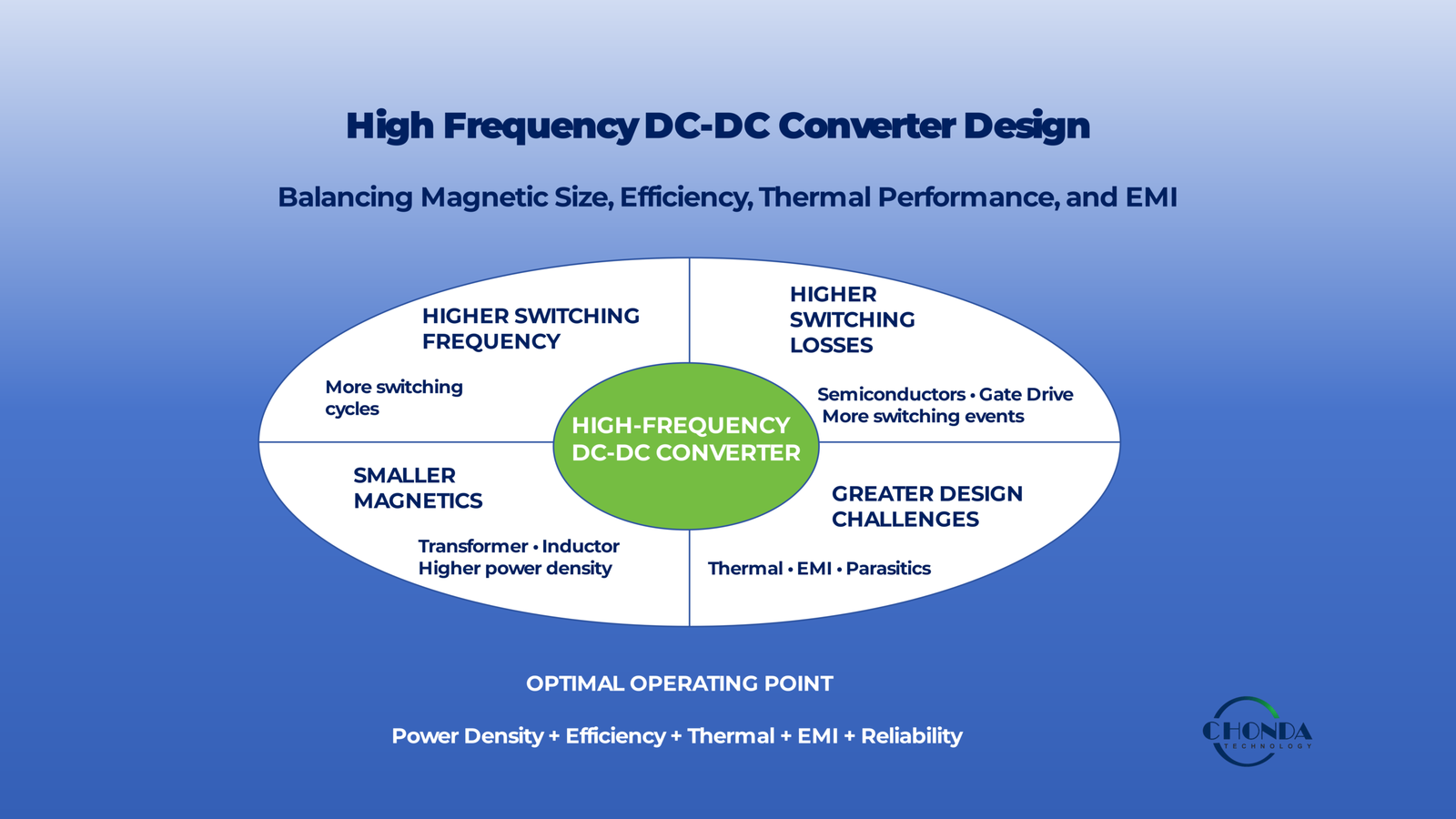
High Frequency DC-DC Converter Design: Switching Frequency, Efficiency, and EMI
Increasing switching frequency is one of the most effective ways to reduce the size of magnetic components in a DC-DC converter and increase power density.
However, higher switching frequency does not automatically produce a better power converter.
As switching frequency increases, the design must manage a changing set of electrical, magnetic, thermal, and electromagnetic trade-offs.
Higher frequency can help reduce the size of transformers and inductors, but it can also increase switching losses, magnetic losses, thermal density, and the potential for high-frequency noise and parasitic coupling.
The practical design challenge is therefore not simply to operate a DC-DC converter at the highest possible frequency.
Instead, engineers must determine an operating point that provides an appropriate balance among:
- Magnetic size
- Switching losses
- Efficiency
- Thermal performance
- EMI
- Power density
- Reliability
This becomes especially important in high-voltage DC-DC converters used in compact industrial equipment, PV monitoring systems, robotics, energy-storage systems, and other applications where space and thermal performance are limited.
This guide explains how switching frequency affects the design of a high-frequency DC-DC converter and why frequency selection should be treated as a system-level engineering decision rather than an isolated specification.
1. Why Increase Switching Frequency?
Switching frequency determines how many times the power-conversion stage transfers energy during a given period of time.
Increasing the switching frequency allows the power stage to transfer energy in more switching cycles per second. This can reduce the amount of energy that must be transferred during each individual cycle and can allow magnetic components such as transformers and inductors to be designed with smaller physical dimensions.
For high-frequency DC-DC converters, this can provide an important advantage when space and power density are critical.
1.1 Smaller Magnetic Components
For a given power-conversion requirement, operating at a higher frequency can allow the transformer or inductor to use a smaller magnetic core and fewer turns than a comparable lower-frequency design.
This can help reduce:
- Transformer volume
- Inductor volume
- Overall converter size
- Weight
- PCB area
This is one of the main reasons high-frequency conversion is widely used in compact power modules.
However, reducing magnetic size does not mean that magnetic design becomes less important.
At higher frequencies, engineers must pay greater attention to core material, winding construction, parasitic effects, and thermal behavior.
1.2 Higher Power Density
Smaller magnetic components can create more space for the rest of the converter and allow more power to be delivered within a smaller physical volume.
This can be valuable in:
- Compact industrial equipment
- Robotics
- Embedded power systems
- PV monitoring electronics
- Battery and energy-storage systems
- High-density power modules
Higher power density can reduce enclosure size and simplify equipment integration when the associated thermal and EMI requirements can also be managed.
1.3 Faster Energy Transfer
A higher switching frequency increases the number of switching cycles available for transferring energy.
This can provide more flexibility in controlling the power-conversion process and can support smaller energy-storage components within the converter.
The exact benefit depends on the selected topology and control method. Frequency alone does not determine converter performance.
1.4 Smaller Filters and Passive Components
Higher-frequency operation can also reduce the physical size of some filtering and energy-storage components.
For example, depending on the topology, higher-frequency ripple can allow smaller inductors, transformers, or filtering elements to achieve the required electrical behavior.
This can contribute further to overall converter size reduction.
However, smaller passive components may also operate at higher electrical or thermal stress, so the reduction in physical size must be evaluated together with component losses and operating temperature.
1.5 Why Frequency Cannot Simply Be Increased Indefinitely
The main limitation is that higher frequency also increases the number of switching transitions occurring every second.
This can increase losses associated with:
- Semiconductor switching
- Gate drive
- Parasitic capacitance
- Magnetic materials
- Winding effects
As a result, the benefits of smaller magnetic components can eventually be offset by higher losses and increased thermal or EMI challenges.
This creates an important engineering trade-off:
Higher Switching Frequency → Smaller Magnetics → Higher Switching and Magnetic Challenges
The objective is therefore not to maximize switching frequency.
The objective is to find a frequency range where the benefits in size and power density justify the additional electrical, thermal, and electromagnetic challenges.
The next step is to examine how higher switching frequency changes transformer and inductor design, particularly the choice of magnetic materials and winding structures.
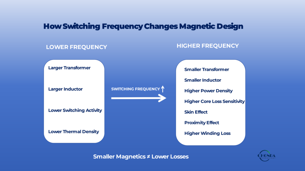
2. How Switching Frequency Changes Magnetic Design
Increasing switching frequency changes the way transformers and inductors transfer and store energy.
For a given power level, higher frequency can reduce the amount of magnetic energy that must be transferred during each switching cycle. This can allow smaller magnetic cores and fewer turns, which helps reduce the physical size of the converter.
However, the reduction in magnetic size comes with additional magnetic and winding losses that become increasingly important as frequency rises.
The key engineering trade-off is therefore:
Higher Frequency → Smaller Magnetics → Greater High-Frequency Magnetic Challenges
2.1 Transformer and Inductor Size
A higher switching frequency can allow a transformer or inductor to transfer the required energy using a smaller magnetic structure.
For a transformer, higher frequency can allow fewer primary and secondary turns for a given voltage and flux-density constraint.
For an inductor, higher frequency can reduce the energy that must be handled during each switching interval, which can allow a smaller core and winding structure depending on the converter topology.
This reduction in magnetic size is one of the main reasons high-frequency switching is attractive for compact DC-DC converters.
2.2 Core Material Becomes More Important
The magnetic core must be suitable for the intended switching frequency.
Core materials are not characterized by one universal loss value. Their behavior depends on factors such as:
- Switching frequency
- Flux density
- Temperature
- Core geometry
- Waveform
A material that performs well at one frequency may not be the most appropriate choice at a substantially higher frequency.
For high-frequency converters, engineers therefore need to consider the magnetic material and operating frequency together.
2.3 Flux Density and Magnetic Stress
Flux density is another important design variable.
The transformer core must operate within an appropriate flux-density range to avoid excessive magnetic stress or saturation.
Increasing switching frequency can provide more flexibility because the required volt-seconds per switching cycle can be distributed across a larger number of cycles.
However, the actual flux-density requirement depends on the topology, waveform, duty cycle, winding turns, and operating voltage.
Higher frequency does not remove the need to control flux density.
2.4 Core Loss Increases with Frequency
One of the main penalties of increasing frequency is that core loss can increase.
Magnetic core loss depends on several variables, including:
- Frequency
- Flux density
- Core material
- Temperature
- Excitation waveform
As switching frequency rises, the magnetic core may dissipate more energy even though the physical core becomes smaller.
This creates an important trade-off:
Smaller Core ≠ Lower Magnetic Loss
A smaller magnetic component can be beneficial for power density while still generating significant heat.
The core must therefore be selected and operated so that its loss remains acceptable under the intended conditions.
2.5 Winding Loss Changes at High Frequency
Winding losses also become more complicated as switching frequency increases.
At relatively low frequencies, winding resistance can often be estimated mainly from the conductor’s DC resistance.
At higher frequencies, current distribution within the conductor becomes non-uniform.
Two important effects are:
Skin Effect
Current tends to concentrate toward the outer region of a conductor as frequency increases.
This can increase the effective AC resistance of the winding.
Proximity Effect
Magnetic fields generated by nearby conductors can cause current to redistribute within the winding.
This can further increase effective AC resistance and winding loss.
These effects are particularly important in high-frequency transformers and inductors where compact winding structures are combined with rapidly changing currents.
2.6 Winding Construction Matters
As frequency increases, the physical arrangement of the winding becomes an increasingly important part of the magnetic design.
Engineers may need to consider:
- Conductor diameter
- Number of strands
- Litz wire where appropriate
- Foil conductors
- Layer arrangement
- Interleaving
- Winding window utilization
- Insulation thickness
The optimal winding construction depends on the operating frequency, current, voltage, insulation requirements, and converter topology.
Reducing the physical size of the magnetic component without controlling winding losses can result in a compact design with unacceptable temperature rise.
2.7 Smaller Magnetics Can Create Higher Thermal Density
A smaller transformer or inductor occupies less physical space, but the heat generated inside that smaller structure may become more concentrated.
This can make thermal management more difficult.
For example, a converter may achieve a significant reduction in transformer volume while maintaining similar total magnetic losses.
The result can be:
Smaller Volume + Similar Losses → Higher Thermal Density
This is one reason why high-frequency design cannot be evaluated only by component dimensions.
2.8 Leakage Inductance and Parasitic Effects
High-frequency magnetic structures also exhibit parasitic characteristics that can become increasingly important.
These may include:
- Leakage inductance
- Interwinding capacitance
- Stray magnetic fields
- Parasitic capacitance between windings and core structures
These effects can influence switching waveforms, voltage overshoot, common-mode coupling, and overall converter behavior.
They should therefore be considered together with the switching topology and PCB layout.
2.9 The Engineering Trade-Off
The magnetic design challenge can be summarized as:
Higher Switching Frequency
→ Smaller Transformer
→ Smaller Inductor
→ Higher Core-Loss Sensitivity
→ Higher Winding-Loss Sensitivity
→ Greater Skin and Proximity Effects
→ Higher Thermal Density
→ Greater Sensitivity to Parasitics
This is why a high-frequency DC-DC converter should not be designed simply by increasing switching frequency until the magnetic components become as small as possible.
The practical target is to select a frequency and magnetic design that provide the required size and power density while keeping magnetic loss, winding loss, thermal stress, and parasitic effects within acceptable limits.
For broader thermal and high-voltage converter design considerations, see High Voltage DC-DC Converter Thermal Management and High Voltage Power Supply Design Guide.
3. Switching Losses Increase with Frequency
One of the main trade-offs of increasing switching frequency is the additional loss introduced by more frequent switching transitions.
A higher switching frequency allows the converter to transfer energy in more cycles per second, but it also requires the semiconductor devices and their associated gate-drive circuits to switch more frequently.
As frequency increases, switching losses can become an increasingly important part of the converter’s total power loss.
3.1 More Switching Transitions per Second
A semiconductor device does not switch instantaneously between its conducting and blocking states.
During each turn-on and turn-off transition, the device may simultaneously experience significant voltage and current.
The energy dissipated during each transition is then repeated at the switching frequency.
A simplified relationship can be expressed as:
Switching Loss ≈ Energy per Switching Event × Switching Frequency
This means that even when the energy lost in one switching event remains relatively small, repeating that event many more times per second can significantly increase total switching loss.
3.2 Turn-On and Turn-Off Losses
During a switching transition, the semiconductor passes through a period in which voltage and current overlap.
Losses can occur during both:
- Turn-on
- Turn-off
The actual loss depends on factors such as:
- Device type
- Switching voltage
- Switching current
- Switching speed
- Gate-drive behavior
- Parasitic inductance and capacitance
- Converter topology
A faster transition may reduce the time spent in the high-loss switching region, but excessively fast switching can also increase voltage overshoot, ringing, and EMI.
This creates another design trade-off between switching loss and switching speed.
3.3 Gate-Drive Losses
The gate-drive circuit also consumes energy every time a switching device is turned on and off.
For many semiconductor devices, the gate must be charged and discharged repeatedly.
As switching frequency increases, this gate-drive energy is consumed more frequently.
Gate-drive losses can therefore become increasingly relevant in high-frequency converters, particularly when multiple switching devices are used.
Engineers may need to consider:
- Gate charge
- Drive voltage
- Drive resistance
- Switching frequency
- Number of switching devices
The semiconductor cannot therefore be evaluated separately from its gate-drive system.
3.4 Parasitic Capacitance
Semiconductor devices and circuit structures contain parasitic capacitances.
These capacitances must be charged and discharged as switching voltages change.
At higher switching frequencies, the associated energy is transferred more frequently, which can increase switching-related losses.
Parasitic capacitance can also contribute to unwanted current paths and electromagnetic coupling.
The result is that a converter can become increasingly sensitive to physical layout and component parasitics as switching frequency rises.
3.5 Reverse-Recovery and Switching Behavior
In converter topologies that use components with reverse-recovery characteristics, additional switching losses may occur when devices transition between conducting and blocking states.
The actual behavior depends strongly on:
- Semiconductor technology
- Switching topology
- Commutation method
- Switching frequency
- Operating current
Modern semiconductor technologies can reduce certain switching-related losses, but device selection should always be matched to the topology and operating conditions.
3.6 Soft Switching Can Change the Trade-Off
Some high-frequency converter topologies use techniques designed to reduce switching losses by controlling the voltage or current conditions during switching transitions.
Examples include:
- Zero-voltage switching (ZVS)
- Zero-current switching (ZCS)
These approaches can reduce the energy dissipated during switching under appropriate operating conditions.
However, they also introduce additional requirements in topology, control, magnetic design, and operating range.
Soft switching should therefore be evaluated as part of the complete converter architecture rather than treated as a simple way to eliminate switching losses.
3.7 Switching Loss and Thermal Performance
Switching losses eventually become heat.
As switching frequency increases, higher semiconductor losses can increase the thermal load even while the magnetic components become smaller.
This creates an important system-level trade-off:
Higher Frequency → Smaller Magnetics
but also:
Higher Frequency → More Switching Events → Potentially Higher Switching Loss → Higher Thermal Load
The thermal consequences depend on the semiconductor technology, topology, efficiency, cooling conditions, and operating power.
3.8 Why the Highest Switching Frequency Is Not Always Best
It may appear attractive to increase switching frequency as much as possible to minimize the size of the magnetic components.
However, beyond a certain point, the additional switching losses may outweigh the benefits gained from further reducing magnetic size.
The optimum operating point depends on the complete converter design.
Engineers should therefore evaluate:
Magnetic Size + Switching Loss + Thermal Performance + EMI + Reliability
rather than optimizing frequency as an isolated parameter.
The practical goal is to select a switching frequency that provides the required power density while keeping semiconductor losses and thermal stress within acceptable limits.
For detailed EMI considerations associated with switching behavior, see High Voltage DC-DC Converter EMI Design Considerations. For system-level thermal considerations, see High Voltage DC-DC Converter Thermal Management.
4. Efficiency Trade-Off at High Frequency
Increasing switching frequency can reduce the size of magnetic components, but the associated increase in switching and magnetic losses can reduce overall converter efficiency.
This creates a fundamental trade-off in high-frequency DC-DC converter design.
The objective is not to maximize switching frequency or efficiency independently. Instead, engineers need to identify an operating point where the benefits of smaller magnetic components and higher power density are balanced against switching losses, magnetic losses, thermal stress, and EMI.
4.1 Different Losses Respond Differently to Frequency
Total converter loss is made up of several different mechanisms, and they do not all change in the same way as switching frequency increases.
Typical losses include:
- Semiconductor conduction losses
- Switching losses
- Gate-drive losses
- Transformer core losses
- Winding losses
- Inductor losses
- Rectification losses
- PCB and interconnection losses
Some losses are strongly affected by switching frequency, while others depend more directly on voltage, current, temperature, or component resistance.
This means that changing the switching frequency can improve one part of the design while making another part less efficient.
4.2 Why Higher Frequency Can Reduce Size but Increase Loss
A higher switching frequency can reduce transformer and inductor size because the magnetic components can transfer or store the required energy over more switching cycles.
At the same time, the semiconductor devices switch more frequently, increasing the number of switching transitions per second.
The result can be:
Higher Frequency → Smaller Magnetics
but also:
Higher Frequency → Higher Switching and Magnetic Losses
The point at which the additional losses become significant depends on the topology, semiconductor technology, magnetic design, and operating power.
4.3 Efficiency Depends on the Operating Point
Converter efficiency should not be treated as a single fixed number.
Efficiency can change with:
- Input voltage
- Output power
- Load level
- Switching frequency
- Ambient temperature
- Operating mode
A converter may achieve excellent efficiency at one operating point while showing noticeably different performance at light load, high input voltage, or another switching frequency.
For this reason, high-frequency converter design should evaluate efficiency across the range of conditions that the equipment will actually experience.
4.4 The Trade-Off Between Size and Efficiency
In compact equipment, engineers may accept a modest efficiency penalty if a significant reduction in converter size enables better system integration.
For example, a smaller transformer may allow the converter to fit into a restricted enclosure or PCB area.
However, the additional power loss created by the higher operating frequency still needs to be removed as heat.
A smaller converter can therefore create a higher thermal density even when its total output power has not changed.
The real engineering objective is not simply:
Make the converter smaller.
It is:
Achieve the required size and power density without creating unacceptable losses or thermal stress.
4.5 There May Be an Optimum Frequency Range
For a given converter architecture, there may be a practical frequency range in which the overall system performance is well balanced.
At relatively low frequency:
- Magnetic components may become larger.
- Power density may be lower.
- Passive components may require more physical space.
At increasingly high frequency:
- Switching losses may increase.
- Magnetic losses may become more significant.
- Thermal density may increase.
- EMI challenges may become more difficult.
Between these extremes, engineers may find an operating region that provides a practical compromise between size, efficiency, thermal performance, and electromagnetic behavior.
The optimum point depends on the complete converter design.
4.6 Semiconductor Technology Changes the Trade-Off
The practical high-frequency limit of a converter is also influenced by the semiconductor devices used in the power stage.
Different device technologies have different characteristics related to:
- Switching speed
- Conduction loss
- Gate charge
- Output capacitance
- Voltage capability
- Thermal performance
Advances in semiconductor technology can make higher-frequency operation more practical, but the benefits still depend on the converter topology and magnetic design.
The semiconductor should therefore be selected together with the intended switching frequency rather than independently.
4.7 Efficiency Should Be Evaluated Together with System Requirements
The most efficient operating point is not always the best overall engineering solution.
An industrial converter may need to balance:
Efficiency + Power Density + Thermal Performance + EMI + Reliability + Cost
For example, reducing switching frequency may improve semiconductor efficiency but require larger magnetic components.
Increasing frequency may reduce magnetic volume but increase switching losses and thermal requirements.
The appropriate operating point depends on what the final equipment actually needs.
4.8 The Practical Design Objective
High-frequency DC-DC converter design should therefore focus on finding an appropriate balance rather than pursuing the highest possible switching frequency.
A practical design objective can be summarized as:
Smaller Magnetics + Acceptable Switching Loss + Controlled Magnetic Loss + Manageable Thermal Load + Acceptable EMI
The best switching frequency is the one that allows the converter to meet its electrical and mechanical requirements while maintaining acceptable efficiency and long-term reliability.
For broader system-level discussion of efficiency and power density, see High Voltage Power Supply Design Guide.
5. EMI as a Consequence of High-Frequency Switching
Increasing switching frequency can improve power density, but it can also make electromagnetic interference (EMI) more difficult to control.
The main reason is not simply that a converter operates at a higher frequency. High-frequency operation is usually accompanied by faster voltage and current transitions, which can increase the effect of parasitic inductance and capacitance throughout the power stage.
For this reason, switching frequency, switching speed, parasitics, and EMI should be considered together.
5.1 Higher Frequency Means More Switching Events
A higher switching frequency means that the converter generates more switching transitions per unit of time.
Each transition can create a small amount of unwanted electromagnetic energy. As the number of transitions increases, the overall high-frequency noise environment can become more challenging.
The result depends on:
- Switching frequency
- Voltage
- Current
- Switching speed
- Converter topology
- Physical layout
Frequency alone therefore does not determine EMI performance.
5.2 Fast Voltage Transitions and dv/dt
High-frequency converters often use fast switching edges to reduce switching losses.
Rapid voltage transitions create high dv/dt, which can drive displacement currents through parasitic capacitances.
These parasitic paths may exist:
- Across semiconductor devices
- Between transformer windings
- Between power traces and ground
- Between switching nodes and nearby structures
- Across isolation barriers
As a result, higher-frequency switching can increase common-mode coupling even when the desired power-conversion function is working correctly.
5.3 Fast Current Transitions and di/dt
Rapid changes in current create high di/dt.
When current changes quickly through parasitic inductance, voltage spikes and ringing can occur.
These effects can increase:
- Switching stress
- Conducted noise
- Radiated noise
- Semiconductor voltage overshoot
- Electromagnetic coupling
The physical size of a current loop therefore becomes increasingly important as switching speed increases.
5.4 Parasitic Capacitance Becomes More Significant
Parasitic capacitance is unavoidable in real power converters.
In an isolated DC-DC converter, the transformer itself can provide a high-frequency capacitive path between primary and secondary circuits.
At higher switching frequencies and faster voltage transitions, these parasitic capacitances can carry more unwanted common-mode current.
This is particularly relevant when sensitive measurement, communication, or control circuits are located near the power-conversion stage.
5.5 Higher Frequency Can Increase EMI Sensitivity
A converter operating at high frequency may therefore become more sensitive to:
- PCB geometry
- Switching-loop area
- Transformer construction
- Grounding
- Return-current paths
- Shielding
- Filtering
A design that performs adequately at a lower switching frequency may require additional optimization after the operating frequency is increased.
This does not mean that high-frequency converters are inherently noisy. It means that physical design becomes increasingly important as switching speed increases.
5.6 Switching Speed and Switching Frequency Are Not the Same
These two concepts should not be confused.
Switching frequency describes how often the converter repeats its switching cycle.
Switching speed describes how quickly the voltage or current changes during an individual transition.
A converter can operate at a moderate switching frequency while still using very fast switching edges and therefore generate significant EMI.
Conversely, a higher-frequency converter may use controlled switching edges to manage some of the associated noise.
Engineers should therefore consider both frequency and edge rate.
5.7 High-Frequency Design Requires a System-Level Trade-Off
Increasing switching frequency may provide:
Smaller Magnetics + Higher Power Density
but can also introduce:
More Switching Events + Higher dv/dt and di/dt + Greater Parasitic Sensitivity
The correct design therefore depends on how effectively these effects can be managed through semiconductor selection, magnetic construction, circuit topology, PCB layout, grounding, and filtering.
Detailed EMI mitigation techniques are beyond the scope of this article and are covered in High Voltage DC-DC Converter EMI Design Considerations.
5.8 The Practical Design Principle
The goal of high-frequency DC-DC design is not to eliminate all electromagnetic activity.
The goal is to control the generated energy and its coupling paths so that the converter meets the required EMC performance while maintaining the desired efficiency and power density.
A practical design sequence is:
Switching Frequency → Switching Speed → Parasitics → Coupling Paths → EMI Performance
Understanding this relationship helps engineers choose a practical high-frequency operating point before moving into detailed EMI mitigation and PCB optimization.
6. Thermal Impact of High-Frequency Design
Higher switching frequency can reduce the physical size of magnetic components, but it can also increase the thermal challenges inside a DC-DC converter.
The main reason is that higher-frequency operation can increase switching losses and high-frequency magnetic losses. When these losses are concentrated within a smaller converter, the resulting thermal density can increase even if the total converter size becomes smaller.
For this reason, high-frequency design should always be evaluated together with thermal performance.
6.1 Higher Frequency Can Increase Heat Generation
As discussed earlier, increasing switching frequency can increase:
- Semiconductor switching losses
- Gate-drive losses
- Magnetic core losses
- Winding losses
These losses are converted into heat within the power stage.
The actual increase depends on the converter topology, semiconductor devices, magnetic materials, switching speed, load level, and operating conditions.
6.2 Smaller Components Can Mean Higher Thermal Density
One of the main advantages of high-frequency operation is smaller magnetic components.
However, reducing physical volume does not necessarily reduce total power loss by the same proportion.
For example, a smaller transformer may occupy less space while still generating a similar amount of magnetic loss.
This can lead to:
Smaller Volume + Similar Losses → Higher Thermal Density
Higher thermal density can make it more difficult to transfer heat away from the internal components.
6.3 Semiconductor Temperature Can Become a Limiting Factor
At high switching frequencies, semiconductor losses can become a significant part of the total converter loss.
Engineers may therefore need to consider:
- Junction temperature
- Thermal resistance
- Switching loss
- Conduction loss
- Gate-drive loss
- Cooling conditions
A device that is electrically capable of operating at a given voltage and current may still be unsuitable if its thermal performance is insufficient at the selected switching frequency.
6.4 Magnetic Thermal Performance
High-frequency transformers and inductors can experience both core and winding losses.
As frequency increases, these losses can become more sensitive to:
- Core material
- Flux density
- Winding structure
- Skin effect
- Proximity effect
- Temperature
The magnetic component therefore needs to be designed not only for electrical conversion and isolation, but also for acceptable temperature rise.
6.5 Compact Design Can Make Cooling More Difficult
High power density often means that more heat is generated within a smaller physical volume.
This can create challenges related to:
- Heat spreading
- Airflow
- Heat-sink placement
- PCB thermal paths
- Component spacing
- Enclosure temperature
A compact design may therefore require more careful thermal integration than a larger converter with the same output power.
6.6 Thermal Performance Depends on the Complete System
The actual temperature of a high-frequency converter depends on more than the converter itself.
Important system-level factors include:
- Ambient temperature
- Enclosure design
- Airflow
- PCB structure
- Nearby heat sources
- Mounting arrangement
- Cooling method
A converter that performs well in an open laboratory environment may behave differently when installed inside a compact industrial enclosure.
6.7 Frequency Selection and Thermal Margin
Switching frequency should therefore be selected together with the available thermal margin.
A higher operating frequency may provide useful reductions in magnetic size, but the resulting increase in switching and magnetic losses must remain within an acceptable thermal range.
A practical design review should consider:
Switching Frequency → Power Loss → Temperature Rise → Cooling Requirement → Reliability
The most suitable operating frequency is therefore the one that delivers the required power density without creating unacceptable thermal stress.
6.8 High-Frequency Thermal Design Is a Trade-Off
The overall relationship can be summarized as:
Higher Frequency → Smaller Magnetics + Higher Switching Activity
which can lead to:
Higher Power Density + Greater Thermal Density
This does not mean that high-frequency converters are inherently difficult to cool. With appropriate semiconductor selection, magnetic design, PCB thermal paths, and cooling methods, high-frequency operation can provide excellent power density and reliable performance.
For a broader discussion of thermal design, temperature rise, cooling, and derating, see High Voltage DC-DC Converter Thermal Management.
The key point is that thermal performance should be considered when selecting the switching frequency, not only after the converter has been designed.
7. High Frequency vs. Power Density
Power density is one of the main reasons engineers consider high-frequency operation for DC-DC converters.
By allowing smaller transformers, inductors, and some passive components, higher switching frequency can help reduce the physical volume required for a given power level.
However, power density is a system-level result. It depends not only on magnetic size, but also on semiconductor losses, thermal management, EMI, mechanical integration, and reliability.
7.1 Why Higher Frequency Can Increase Power Density
Higher switching frequency allows magnetic components to process energy over more switching cycles per second.
This can reduce the physical size of:
- Transformers
- Inductors
- Filters
- Other magnetic or energy-storage components
The reduction in passive-component size can free space for other parts of the converter and make a more compact power architecture possible.
For equipment with strict size or weight limits, this can be a significant advantage.
7.2 Power Density Is More Than Magnetic Size
A smaller transformer does not automatically mean a smaller complete converter.
Other components still require physical space, including:
- Power semiconductors
- Heat-spreading structures
- Capacitors
- Gate-drive circuits
- EMI filters
- Connectors
- Insulation barriers
- Mechanical mounting features
In high-voltage systems, creepage and clearance requirements can also limit how closely components can be placed.
The final converter size is therefore determined by the complete mechanical and electrical architecture.
7.3 Higher Power Density Can Increase Thermal Density
As more power is placed into a smaller physical volume, heat generation can become more concentrated.
This can result in higher thermal density even when the total converter output power remains unchanged.
The design may therefore require:
- Better heat spreading
- More effective PCB thermal paths
- Improved airflow
- Heat sinks
- Lower component losses
Power density should therefore always be evaluated together with thermal performance.
7.4 EMI Can Also Limit Practical Power Density
Compact layouts can reduce physical distance between switching nodes and sensitive circuits.
If high-frequency current paths, switching nodes, or transformer structures are placed too close to sensitive circuitry, electromagnetic coupling can become more difficult to control.
A very compact layout may therefore require more careful:
- Switching-loop design
- Grounding
- Shielding
- Filtering
- Physical separation
The goal is not simply to minimize every distance.
The goal is to use the available space in a way that satisfies electrical, thermal, insulation, and EMI requirements simultaneously.
7.5 High Power Density Requires System Optimization
A practical high-density converter usually depends on several design improvements working together:
Higher Switching Frequency
→ Smaller Magnetics
Optimized Semiconductor Selection
→ Lower Switching and Conduction Losses
Optimized Magnetic Design
→ Lower Core and Winding Losses
Effective Thermal Design
→ Higher Usable Power Density
Controlled EMI
→ Reliable System Integration
This is why power density should be considered a system-level outcome rather than a single component specification.
7.6 Mechanical Constraints Also Matter
The practical value of higher power density depends on the equipment in which the converter will be installed.
Engineers may need to consider:
- PCB dimensions
- Enclosure volume
- Mounting height
- Connector placement
- Heat-sink space
- Airflow
- High-voltage spacing
A converter that is physically small but difficult to mount, cool, or isolate may not provide a real system-level advantage.
7.7 The Goal Is Useful Power Density
The objective of high-frequency design is therefore not to achieve the highest possible watts per cubic centimeter at any cost.
A more useful target is:
Required Power + Acceptable Temperature + Controlled EMI + Adequate Isolation + Reliable Operation
A converter that delivers slightly lower power density but provides significantly better thermal performance or easier system integration may be the better engineering solution.
7.8 High Frequency Is a Tool, Not the Final Objective
Higher switching frequency can be an effective tool for increasing power density, but it is only one part of the design strategy.
The practical result depends on the interaction among:
Frequency → Magnetics → Semiconductor Losses → Thermal Design → EMI → Mechanical Integration
A high-frequency DC-DC converter provides real value when these areas are optimized together.
The best design is therefore not necessarily the smallest converter.
It is the converter that achieves the required power density while maintaining acceptable efficiency, thermal performance, EMI, isolation, and long-term reliability.
8. How to Choose a Practical Switching Frequency
There is no single switching frequency that is optimal for every high-frequency DC-DC converter.
The appropriate operating frequency depends on the converter topology, input voltage, power level, semiconductor technology, magnetic design, thermal limits, EMI requirements, and mechanical constraints.
Engineers should therefore select switching frequency as part of the complete converter design rather than treating it as an independent specification.
8.1 Start with the Converter Topology
Different converter topologies have different practical frequency ranges.
The selected topology determines:
- How energy is transferred
- How many switching devices are involved
- Switching transitions
- Magnetic requirements
- Control complexity
- Soft-switching opportunities
A frequency that works well for one topology may not provide the same benefits in another.
The switching frequency should therefore be considered together with the topology from the beginning.
8.2 Consider the Power Level
Power level is another important factor.
At relatively low power, increasing switching frequency can sometimes provide useful reductions in magnetic and passive-component size with manageable losses.
As power increases, however, the total switching and magnetic losses can become more significant.
Higher-power converters may therefore require a more careful balance between:
Magnetic Size + Switching Loss + Thermal Performance
The practical frequency range depends on how efficiently the selected power stage can handle these losses.
8.3 Match the Frequency to the Semiconductor Technology
The semiconductor devices place an important practical limit on switching frequency.
Engineers should consider:
- Voltage rating
- Current rating
- Switching speed
- Gate charge
- Output capacitance
- Conduction loss
- Switching loss
- Thermal characteristics
Different semiconductor technologies can have significantly different high-frequency performance.
The selected device technology should therefore be matched to the intended switching frequency rather than choosing frequency first and the semiconductor afterward.
8.4 Consider the Magnetic Design
The switching frequency and magnetic design should be developed together.
Engineers should evaluate:
- Core material
- Flux density
- Core loss
- Winding loss
- Skin effect
- Proximity effect
- Transformer size
- Inductor size
Increasing frequency can reduce the size of the magnetic components, but only until the additional magnetic and winding losses become unacceptable.
The practical frequency range is therefore closely related to the chosen magnetic materials and construction.
8.5 Consider Thermal Limits
The selected frequency should also be compatible with the available thermal budget.
A higher frequency may reduce magnetic volume while increasing semiconductor and magnetic losses.
Engineers should therefore evaluate:
Switching Frequency → Power Loss → Temperature Rise → Cooling Requirement
If the resulting thermal density is too high, reducing the switching frequency may provide a better overall solution even if the magnetic components become somewhat larger.
8.6 Consider EMI Requirements
Frequency selection can also influence electromagnetic compatibility.
Engineers should consider:
- Switching frequency
- Switching edge rate
- dv/dt
- di/dt
- Parasitic capacitance
- Current-loop geometry
- Filtering
- Grounding
The goal is not simply to choose the lowest possible frequency to reduce EMI.
Instead, the frequency and switching behavior should be selected so that the required power density and efficiency can be achieved while keeping EMI manageable.
For detailed EMI mitigation techniques, see High Voltage DC-DC Converter EMI Design Considerations.
8.7 Consider the Mechanical Target
The required physical size of the final converter can influence the acceptable switching frequency.
If the equipment has very limited space, a higher frequency may provide valuable reductions in magnetic and passive-component volume.
If space is less restrictive, a somewhat lower switching frequency may provide better thermal or EMI performance without creating a significant mechanical disadvantage.
The frequency should therefore be evaluated against the actual enclosure and PCB requirements.
8.8 Look for a Practical Operating Range
Instead of asking:
What is the highest switching frequency possible?
a better engineering question is:
What switching-frequency range provides the required size and power density while maintaining acceptable efficiency, thermal performance, EMI, and reliability?
A practical frequency range should satisfy:
Topology + Semiconductor + Magnetics + Thermal + EMI + Mechanical Requirements
The exact operating point can then be refined through simulation, prototype testing, and validation.
8.9 Frequency Selection Is an Optimization Problem
The final switching frequency is usually the result of balancing several competing objectives:
Higher Frequency
→ Smaller Magnetics
→ Higher Potential Power Density
Lower Frequency
→ Lower Switching Activity
→ Potentially Lower Switching Loss and EMI Stress
Neither direction is universally better.
The best operating point is the one that provides the required system performance within the available thermal, electromagnetic, mechanical, and reliability constraints.
In practical high-frequency DC-DC converter design, switching frequency should therefore be treated as an optimization variable, not as a target that should always be maximized.
9. When High-Frequency DC-DC Design Makes Sense
High-frequency switching is particularly valuable when the physical size, weight, or power density of a DC-DC converter is an important system requirement.
However, high-frequency operation should be selected because it solves a real system constraint rather than simply because a higher switching frequency appears technically attractive.
Several types of applications can benefit from a high-frequency DC-DC architecture.
9.1 Compact Industrial Electronics
Industrial equipment may have limited PCB area or enclosure space while still requiring a regulated power supply.
In these systems, reducing the size of transformers, inductors, and filtering components can help engineers:
- Reduce PCB area
- Reduce enclosure volume
- Simplify mechanical integration
- Increase the amount of functionality within a limited space
High-frequency conversion can therefore be useful when electrical and mechanical integration are both important.
9.2 Robotics and Embedded Systems
Robotics and embedded equipment often place strict constraints on size and weight.
A compact DC-DC converter can help provide the required power without consuming excessive space or adding unnecessary mass.
Typical considerations may include:
- Power density
- Efficiency
- Thermal performance
- Input-voltage range
- Mechanical dimensions
- EMI
In battery-powered or DC-bus-based systems, high-frequency isolated conversion can be particularly useful when multiple power domains need to be created within a compact enclosure.
9.3 PV Monitoring Systems
PV monitoring equipment can require isolated auxiliary power from a relatively high-voltage DC source while operating within limited installation space.
A high-frequency DC-DC converter can help reduce the size of magnetic components while providing the required regulated output.
Typical design priorities may include:
- High-voltage DC input
- Galvanic isolation where required
- Compact size
- Low auxiliary power consumption
- Thermal stability
- EMI performance
The practical value of high-frequency design in this application comes from combining compact magnetic components with reliable high-voltage and low-voltage power-domain integration.
9.4 Battery and Energy-Storage Systems
Battery and energy-storage systems may contain high-voltage DC buses together with monitoring, communication, control, and protection electronics.
A compact DC-DC converter can provide power to these subsystems while helping maintain separation between different power domains where required.
High-frequency design may be useful when:
- Installation space is limited
- Multiple voltage rails are required
- Power density is important
- Thermal performance can be adequately managed
The available battery-voltage range and system operating temperature should still be considered when selecting the converter architecture and switching frequency.
9.5 High-Density Power Modules
High-frequency switching can be particularly valuable for applications where the power module itself must fit into a compact standardized mechanical envelope.
Reducing transformer and inductor volume can make it easier to:
- Increase output power within a fixed volume
- Improve packaging flexibility
- Integrate more functions into the same enclosure
- Reduce system-level space requirements
However, achieving high power density requires optimization of the complete power stage rather than frequency alone.
9.6 When High Frequency May Not Be the Best Choice
High-frequency operation is not automatically the best solution for every application.
A lower switching frequency may be preferable when:
- Mechanical space is not restricted
- Thermal conditions are demanding
- EMI requirements are especially stringent
- Magnetic component size is not a major constraint
- The selected semiconductor or magnetic technology is better suited to lower-frequency operation
- Simplicity and cost are prioritized
The appropriate operating point should therefore be determined by the actual system requirements.
9.7 Application Requirements Should Drive Frequency Selection
A practical decision process is:
Application Constraint → Required Power Density → Magnetic Size → Switching Frequency → Thermal / EMI Verification
This keeps switching frequency in its proper role: it is a design tool used to satisfy system requirements rather than an objective by itself.
High-frequency DC-DC conversion makes the most sense when the benefits of smaller magnetic components and higher power density provide a meaningful advantage in the final equipment, and when the resulting switching, thermal, magnetic, and EMI challenges can be managed within acceptable limits.
10. Practical High-Frequency Design Trade-Off
High-frequency DC-DC converter design involves several competing objectives.
Increasing switching frequency can reduce the size of magnetic components and increase power density, but it can also increase switching losses, magnetic losses, thermal density, and sensitivity to parasitic effects and EMI.
For this reason, the switching frequency should be selected according to the complete system requirements rather than optimized for one parameter alone.
10.1 The Main Trade-Offs
A simplified view of the design trade-offs is:
Higher Switching Frequency
→ Smaller Transformers and Inductors
→ Higher Potential Power Density
→ More Switching Events
→ Higher Potential Switching Losses
→ Greater Magnetic-Loss Sensitivity
→ Higher Thermal Density
→ Greater Parasitic and EMI Sensitivity
The actual magnitude of each effect depends on the selected topology, semiconductor technology, magnetic design, switching speed, load level, and operating environment.
10.2 What Engineers Are Really Optimizing
The objective of frequency selection is not simply to minimize magnetic size.
Engineers are typically balancing:
- Converter size
- Power density
- Efficiency
- Thermal performance
- EMI
- Reliability
- Cost
- Mechanical integration
Improving one parameter can create a disadvantage elsewhere.
For example, increasing frequency may reduce transformer volume but increase switching loss.
Reducing magnetic size may increase thermal density.
Using faster switching edges may improve switching performance but make EMI control more demanding.
The best design therefore comes from finding an acceptable operating point across all of these constraints.
10.3 A Practical Frequency-Selection Sequence
A practical design process can be summarized as:
Define Power and Size Requirements
↓
Select Suitable Topology
↓
Evaluate Semiconductor Technology
↓
Estimate Magnetic Size and Loss
↓
Estimate Switching Loss
↓
Check Thermal Conditions
↓
Evaluate EMI and Parasitic Effects
↓
Select a Practical Switching-Frequency Range
↓
Validate with Simulation and Prototype Testing
This sequence helps prevent switching frequency from being selected in isolation from the rest of the converter.
10.4 Higher Frequency Is Not Always the Better Engineering Choice
There is no universal rule that a higher-frequency converter is superior to a lower-frequency design.
A lower-frequency design may provide:
- Lower switching losses
- Lower thermal stress
- Easier EMI control
- Simpler magnetic construction
A higher-frequency design may provide:
- Smaller magnetic components
- Higher power density
- Reduced overall converter volume
- Greater packaging flexibility
The appropriate choice depends on the application.
10.5 The Practical Design Objective
The final goal can be expressed as:
Required Power + Required Size + Acceptable Efficiency + Controlled Thermal Performance + Acceptable EMI + Adequate Reliability
A switching frequency is well chosen when it helps the converter meet these requirements simultaneously.
The engineer should therefore ask:
What switching frequency gives the best overall system performance for this application?
rather than:
What is the highest switching frequency the converter can achieve?
This distinction is central to practical high-frequency DC-DC converter design.
Conclusion
High-frequency switching can be an effective way to reduce magnetic-component size and increase the power density of a DC-DC converter.
However, increasing switching frequency also changes the balance among switching losses, magnetic losses, thermal performance, EMI, parasitic effects, and reliability.
For this reason, switching frequency should not be selected simply to achieve the smallest possible transformer or the highest possible power density.
A practical high-frequency DC-DC converter design should evaluate:
Switching Frequency → Magnetic Design → Switching Loss → Efficiency → Thermal Performance → EMI → Power Density → Reliability
The most suitable operating frequency depends on the converter topology, semiconductor technology, magnetic components, input and output conditions, mechanical constraints, and application requirements.
For compact industrial electronics, PV monitoring, robotics, energy-storage systems, and other high-density applications, higher-frequency operation can provide significant benefits when the associated electrical, thermal, and electromagnetic challenges are properly managed.
The goal is therefore not to maximize switching frequency.
It is to find the practical operating point that provides the required power density, efficiency, thermal performance, EMI control, and reliability for the complete system.
For engineers developing high-frequency DC-DC converters, frequency selection should ultimately be treated as a system-level optimization decision rather than as an isolated component specification.
How CHONDA Supports High-Frequency DC-DC Applications
CHONDA provides DC-DC power modules and high-voltage DC-DC converter solutions for industrial applications where compact size, power density, electrical isolation, and reliable power conversion are important.
Depending on the application, the appropriate switching-frequency range may be influenced by the required input voltage, output power, thermal conditions, EMI requirements, mechanical constraints, and system architecture.
CHONDA works with customers to evaluate these requirements and identify a suitable standard or customized power solution for applications such as PV monitoring, industrial automation, robotics, embedded electronics, and other specialized power systems.
Related Articles
High Voltage Power Supply Design Guide
Explore a system-level framework for high-voltage power-supply architecture, including efficiency, power density, thermal performance, EMI, protection, PCB design, and power-module selection.
What Is a High Voltage DC-DC Converter?
Understand the basic operating principles, architecture, and applications of high-voltage DC-DC converters for industrial power systems.
High Voltage DC-DC Converter EMI Design Considerations
Learn how switching behavior, common-mode noise, differential-mode noise, grounding, filtering, and PCB layout affect EMI performance.
High Voltage DC-DC Converter PCB Design Considerations
Explore how switching loops, return paths, creepage, clearance, grounding, and PCB layout influence high-voltage DC-DC converter performance.
High Voltage DC-DC Converter Thermal Management
Understand power losses, temperature rise, cooling, and derating considerations for reliable high-voltage DC-DC converter operation.
High Voltage DC-DC Converter Isolation Design: Principles and Applications
Review galvanic isolation, insulation requirements, creepage, clearance, and high-voltage isolation architecture.