We help the world since 2012
Grounding Design for PV Monitoring Systems
In photovoltaic (PV) monitoring systems, grounding design plays a critical role in ensuring both signal stability and long-term system reliability. As PV installations often operate in high-voltage and outdoor environments, improper grounding can easily lead to noise interference, communication errors, and even equipment malfunction. A well-designed grounding system helps establish a stable reference potential across the entire monitoring network, allowing devices such as DC-DC converters, PLC modules, RS485 communication units, and sensors to operate with consistent and accurate signals.
1. Why Grounding Is Critical in PV Monitoring Systems
Grounding is one of the most important design factors in photovoltaic monitoring systems. A properly designed grounding system ensures a stable reference potential for all monitoring devices, which is essential for maintaining consistent electrical behavior across the system.
In PV monitoring applications, grounding directly affects system performance in several key areas:
- Stable reference potential for all monitoring devices
- Reduced electromagnetic interference (EMI)
- Protection of communication interfaces (RS485 / PLC / sensors)
- Improved system safety under high-voltage conditions
In high-voltage PV environments, even small grounding design mistakes can lead to communication instability, sensor drift, or data errors. As multiple devices operate within the same electrical network, a well-structured grounding system becomes essential to ensure reliable and accurate monitoring performance.
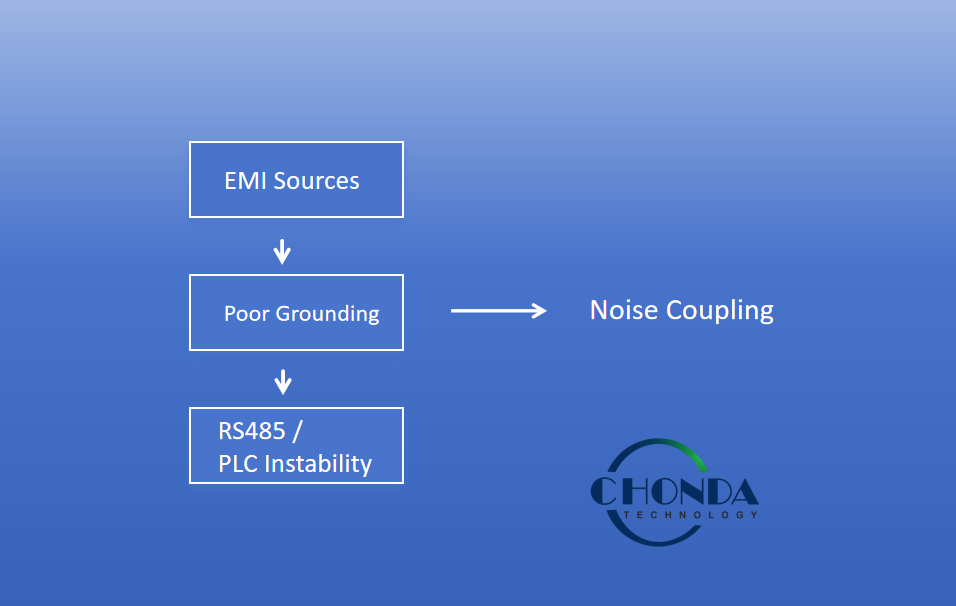
2. How Improper Grounding Causes System Problems
Improper grounding in photovoltaic monitoring systems can introduce a range of electrical and communication issues that are often difficult to diagnose at the early stage. Unlike obvious hardware failures, grounding-related problems usually appear as intermittent or unstable system behavior, especially in high-voltage PV environments.
One of the most common issues is ground potential difference between different devices. When PLCs, RTUs, DC-DC converters, and sensors are referenced to different grounding points, even a small voltage difference can generate unwanted common-mode current. This often results in unstable RS485 communication, random data errors, or temporary loss of signal.
Another frequent problem is ground loops, which occur when multiple grounding paths exist within the same system. Ground loops can unintentionally act as antennas, picking up electromagnetic interference from nearby switching power supplies, inverters, or long DC cable runs. This increases the noise level in the system and reduces the accuracy of monitoring data.
Improper grounding can also lead to increased susceptibility to EMI, especially in installations where signal cables run close to high-voltage DC conductors. Without a low-impedance and well-controlled grounding structure, interference can easily couple into communication lines and sensor circuits.
In severe cases, grounding issues may cause unpredictable resets or malfunction of monitoring equipment, particularly in sensitive devices powered by non-isolated or poorly isolated power supplies.
3. Key Principles of Proper Grounding Design
A properly designed grounding system is essential for ensuring stable operation in photovoltaic monitoring systems. The main objective is to provide a low-impedance, well-controlled reference point for all electronic devices while minimizing noise coupling and potential differences across the system.
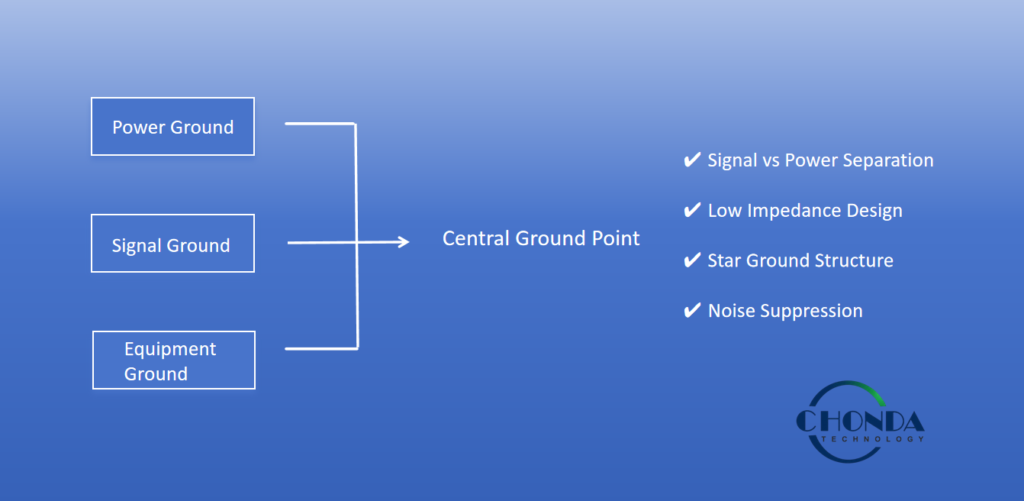
Single-Point Grounding Architecture
In PV monitoring applications, a single-point grounding structure is often preferred to avoid ground loops. All monitoring devices, including DC-DC converters, PLCs, RTUs, and sensors, should be referenced to a common grounding node. This approach helps maintain a consistent electrical potential across the system and reduces the risk of circulating ground currents.
Separation of Power Ground and Signal Ground
Power circuits and signal circuits should not share the same grounding path. High-current return paths from power conversion stages can introduce voltage fluctuations that affect sensitive communication signals. Separating power ground from signal ground helps improve RS485 stability and reduces interference in low-voltage measurement circuits.
Low-Impedance Grounding Design
A grounding system should always be designed with low impedance in mind, especially in high-frequency environments. Short grounding paths, proper conductor sizing, and solid mechanical connections help reduce impedance and improve noise suppression performance. High-impedance grounding paths can easily introduce unwanted voltage fluctuations and degrade system stability.
Star Grounding Topology for Distributed Systems
For distributed PV monitoring systems, a star grounding structure is commonly used. In this configuration, all subsystems are connected individually to a central grounding point rather than being daisy-chained. This minimizes interaction between different grounding paths and improves overall EMC performance.
4. Grounding Best Practices in Field Installations
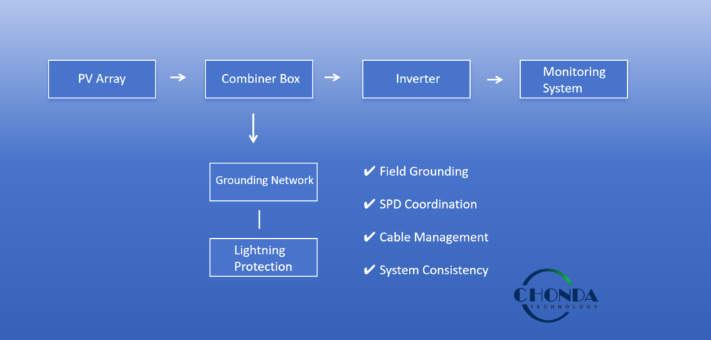
In real photovoltaic monitoring installations, grounding design must account for both electrical performance and environmental conditions. Unlike controlled laboratory environments, field installations are exposed to long cable runs, outdoor electromagnetic noise, lightning surge risks, and complex system layouts.
A key principle is to ensure that all major system components—including combiner boxes, inverters, DC-DC converters, and monitoring cabinets—are connected to a unified grounding network. This helps maintain a consistent reference potential across the entire PV system and reduces the risk of potential differences between distributed devices.
Proper Grounding in Combiner Box and Inverter Systems
Combiner boxes and inverters should be grounded directly to the main grounding system using low-impedance conductors. Avoid relying solely on communication cable shields as grounding paths. Dedicated grounding conductors provide a more stable and reliable electrical reference, especially under high-current or fault conditions.
Cable Routing and Grounding Coordination
Grounding performance is closely related to cable layout. Signal cables such as RS485 or sensor lines should be routed separately from high-voltage DC cables whenever possible. If both must share the same installation path, maintaining adequate spacing and minimizing parallel routing length helps reduce electromagnetic coupling.
Environmental and Lightning Considerations
PV systems installed outdoors are highly exposed to lightning-induced surges and environmental interference. A properly designed grounding system should work together with surge protection devices (SPD) to safely discharge transient energy. This coordination between grounding and protection devices is essential for long-term system reliability.
System-Level Grounding Consistency
Consistency across the entire PV plant is critical. All subsystems should follow the same grounding strategy, whether single-point grounding or star grounding architecture. Mixing different grounding methods within the same system can introduce unpredictable potential differences and reduce EMC performance.
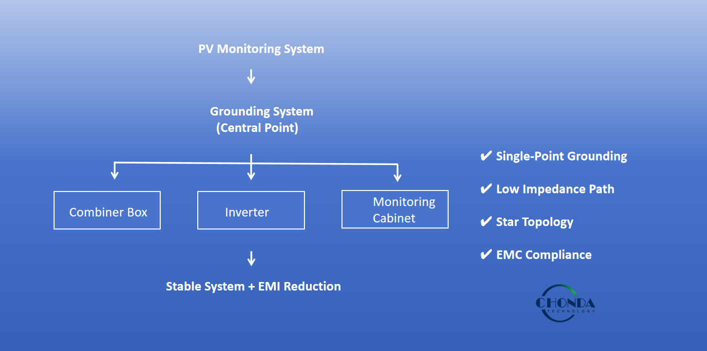
Recommended Grounding Architecture for PV Monitoring Systems
A reliable grounding architecture in photovoltaic monitoring systems must ensure consistent electrical reference, minimize electromagnetic interference, and maintain communication stability across all subsystems. The overall grounding design should be planned at the system level rather than at individual device level.
Centralized Grounding Point Structure
A recommended approach is to use a centralized grounding point as the reference for the entire PV monitoring system. All key components—including combiner boxes, inverters, DC-DC converters, PLC controllers, RTUs, and sensors—should be connected individually to this single grounding node. This star-type grounding structure helps avoid ground loops and ensures consistent potential distribution across the system.
Integration with Power Conversion Units
High-voltage isolated DC-DC converters should be integrated close to the monitoring and control units. By providing galvanic isolation between the PV high-voltage bus and low-voltage electronics, these converters help prevent noise from propagating into communication and sensing circuits. This significantly improves system stability in electrically noisy environments.
Separation of High-Power and Low-Signal Ground Paths
Within the grounding architecture, it is important to physically and electrically separate high-power grounding paths from low-signal reference grounds. Power grounding paths carry higher current and switching noise, while signal grounding must remain clean to ensure reliable RS485 and sensor operation.
Consistency Across Field Equipment
All field-installed equipment should follow the same grounding strategy. Mixing multiple grounding philosophies (for example, combining floating ground and star grounding within the same PV system) can create unpredictable potential differences and increase susceptibility to EMI.
5. Conclusion
A properly designed grounding system is a fundamental requirement for stable and reliable operation of photovoltaic monitoring systems. In high-voltage PV environments, grounding not only affects electrical safety, but also directly influences communication quality, signal stability, and overall system performance.
Through correct grounding architecture design—including single-point grounding, separation of power and signal paths, low-impedance connections, and star topology in field installations—engineers can significantly reduce electromagnetic interference and improve long-term system reliability.
In practical PV applications, grounding design must always be considered together with EMI control, cable routing, and system-level isolation strategies. When combined with isolated DC-DC converters and proper installation practices, a well-structured grounding system becomes a key factor in ensuring stable operation of PLCs, RTUs, RS485 communication networks, and other monitoring devices.
RELATED ARTICLES
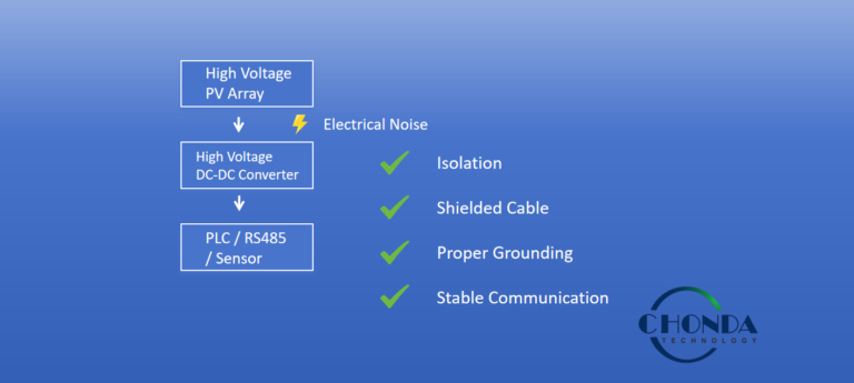
How to Reduce Electrical Noise in PV Monitoring Systems
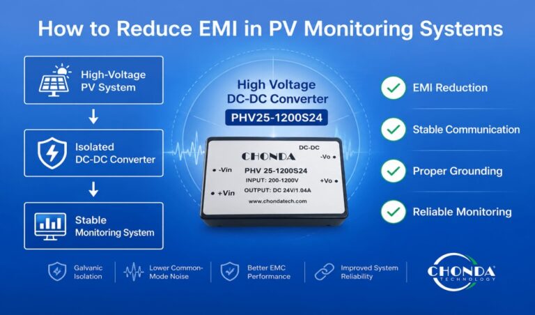
How to Reduce EMI in PV Monitoring Systems
Why Isolated DC-DC Converters Improve PV Monitoring Reliability
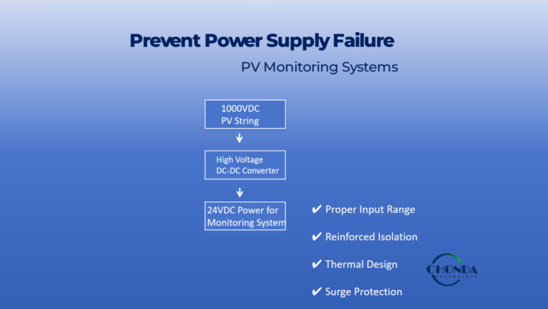
Why PV Monitoring Systems Need Isolated Power Supplies
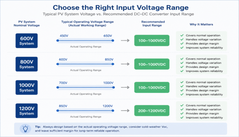
How to Select the Right Input Voltage for PV Monitoring DC-DC Converters