
We help the world since 2012

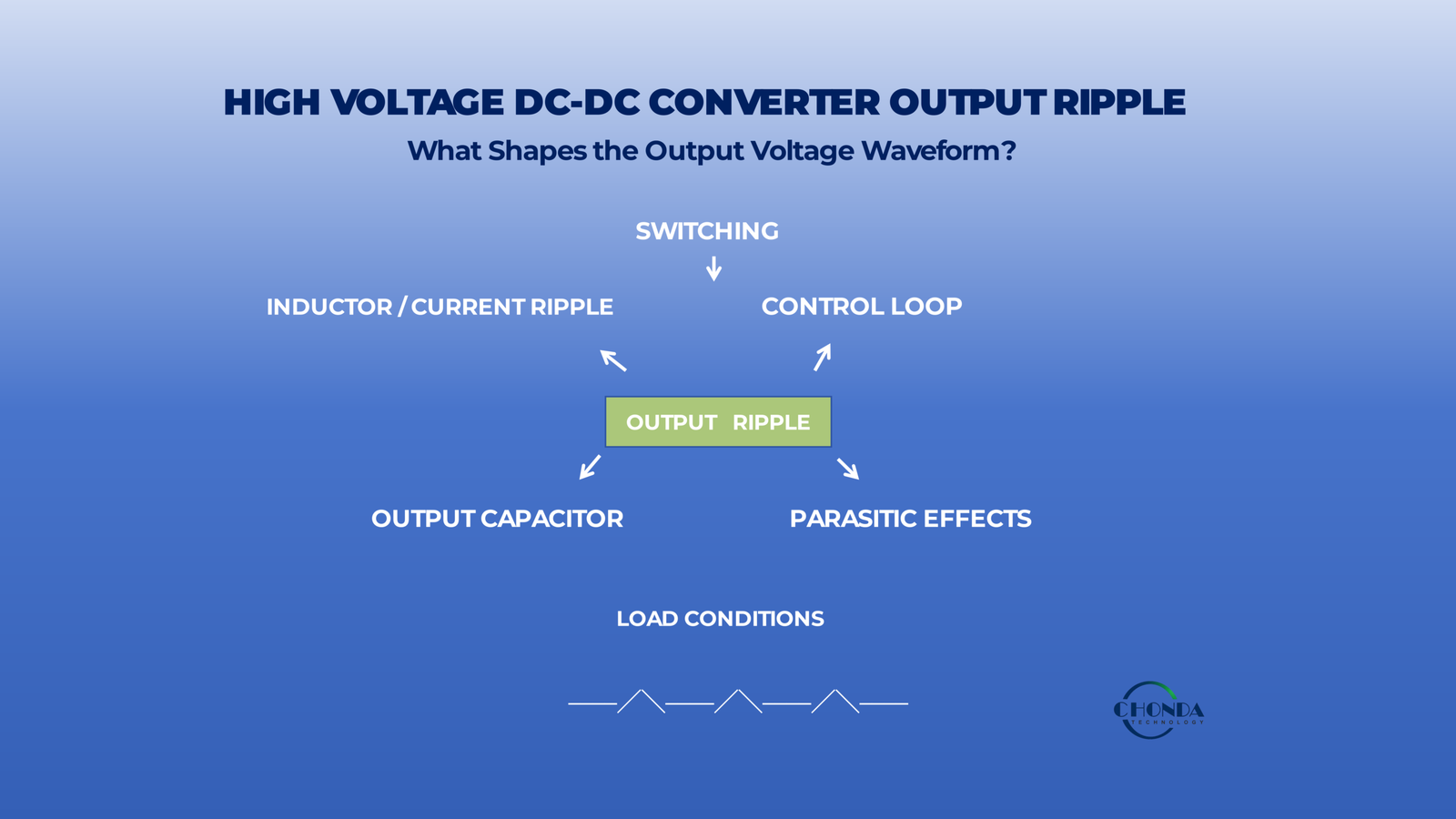
High Voltage DC-DC Converter Output Ripple: Causes and Design Considerations
The output voltage of a DC-DC converter is not always perfectly constant.
Even when a high voltage DC-DC converter provides a regulated DC output, a small amount of periodic voltage variation may remain on the output. This variation is commonly referred to as output ripple.
For industrial power systems, output ripple may affect downstream control circuits, sensors, communication electronics, monitoring systems, and other loads that depend on a stable low-voltage supply.
The challenge is not simply to ask whether a converter has low output ripple.
Engineers also need to understand where the ripple comes from, what factors influence it, how it behaves under different operating conditions, and whether the actual ripple level is acceptable for the downstream application.
Output ripple can be influenced by the converter’s switching frequency, output capacitance, load condition, control loop, PCB layout, magnetic components, and the characteristics of the downstream circuit.
In high voltage DC-DC converter applications, these factors can interact with efficiency, thermal performance, EMI, and output regulation.
Therefore, output ripple should be evaluated as part of the complete converter and load system, rather than as an isolated specification.
Low output ripple is not simply a component-level target. It is the result of converter architecture, filtering, control, layout, and load conditions working together.
This article explains the main causes of output ripple in high voltage DC-DC converters, how engineers can evaluate ripple under realistic operating conditions, and what design considerations can help achieve an appropriate output-voltage quality for the application.
1. What Is Output Ripple in a High Voltage DC-DC Converter?
A high voltage DC-DC converter is designed to convert a DC input into a regulated DC output. However, the output voltage is not perfectly constant under real operating conditions.
A small amount of periodic voltage variation may remain on the DC output. This variation is commonly referred to as output ripple.
For example, a converter may provide a nominal 24VDC output, while the actual output voltage fluctuates slightly around that value:
24V → 24.02V → 23.98V → 24.01V → 24.00V
The average output remains close to the regulated value, but a small AC component is superimposed on the DC voltage.
This distinction is important because output ripple is different from output regulation and transient response.
1.1 Output Ripple
Output ripple is the relatively small, repetitive variation that remains on the output voltage during steady-state operation.
It is commonly associated with the converter’s switching process and the interaction of the power stage with the output filtering network.
A simplified representation is:
DC Output
────────────────────────
       ~~~~~~~~
The horizontal level represents the DC output, while the small periodic variation represents the ripple.
The actual ripple waveform may vary depending on the converter architecture, switching frequency, filtering components, load condition, and control behavior.
Therefore:
Output ripple describes the residual periodic variation superimposed on the converter’s DC output.
1.2 Output Regulation Is Different
Output regulation describes how well the converter maintains its specified output voltage when operating conditions change.
For example, a converter may be specified to provide 24VDC while the input voltage or load changes within its defined operating range.
A converter with good output regulation keeps the average output voltage close to the target value.
This is different from ripple.
A converter could maintain an average output of approximately 24V while still having measurable high-frequency ripple around that value.
Therefore:
Output regulation → How close is the output voltage to the target value?
Output ripple → How much periodic variation remains around that output voltage?
These two parameters are related, but they should not be treated as interchangeable.
1.3 Output Ripple Is Also Different From Transient Response
Output ripple should also be distinguished from a load or input transient.
A transient is typically associated with a relatively sudden change in operating conditions, such as a rapid load change or input disturbance.
For example:
Normal output ────────────────
                              \
                               \____
                                    \────────
This represents a temporary deviation caused by a change in system conditions.
By contrast, ripple is a repeated variation that can remain present while the converter is otherwise operating in a steady state:
────────╱╲────╱╲────╱╲────╱╲────────This distinction matters because the engineering causes and solutions are different.
Ripple is a steady-state output-quality issue; transient response describes how the converter reacts to a sudden operating change.
1.4 What Determines Output Ripple?
Output ripple is not controlled by a single component.
It can be influenced by several parts of the converter design, including:
- switching behavior
- output inductor or magnetic components
- output capacitance
- capacitor ESR and ESL
- control-loop behavior
- PCB layout and parasitic effects
- load condition
The interaction between these elements determines the final voltage waveform observed at the converter output.
For this reason, two converters with the same nominal output voltage can exhibit different ripple characteristics.
1.5 Why Output Ripple Matters in High Voltage DC-DC Applications
The importance of output ripple depends on what is connected to the converter output.
A moderate amount of ripple may be acceptable for some loads, while other applications may require a cleaner supply.
Potentially sensitive loads can include:
- monitoring circuits
- sensors
- communication electronics
- control electronics
- measurement equipment
- signal-processing circuits
In these applications, excessive output ripple may affect downstream electrical performance or interact with other noise-sensitive circuits.
However, the required ripple level should always be considered in relation to the actual load and system requirements.
The objective is not necessarily to achieve the lowest possible ripple under every condition.
Instead, the objective is to achieve output voltage quality appropriate for the application.
1.6 Output Ripple Should Be Evaluated Under Defined Conditions
An output-ripple value is meaningful only when the measurement conditions are also understood.
For example, measured ripple can vary with:
- input voltage
- output load
- operating temperature
- measurement bandwidth
- measurement method
- test-point location
Therefore, a statement such as “output ripple is 50mV” does not provide the complete engineering picture unless the test conditions are known.
This becomes particularly important when comparing different high voltage DC-DC converters.
A more useful comparison should specify how the ripple was measured and under what operating conditions.
1.7 A Practical Definition
For engineering purposes, output ripple can therefore be understood as:
The residual periodic voltage variation present on a DC-DC converter’s output during steady-state operation.
It is one part of overall output performance, alongside:
Output Voltage
Output Regulation
Output Ripple
Transient Response
Noise / EMI
These parameters describe different aspects of the output and should be evaluated according to the requirements of the complete system.
A regulated DC output is not necessarily a perfectly flat DC waveform. Output ripple represents the remaining periodic variation around the regulated output voltage.
The next section will examine where this ripple actually comes from, including the roles of switching, output filtering, magnetic components, control loops, and parasitic effects.
2. What Causes Output Ripple?
Output ripple is the result of several electrical and control mechanisms interacting inside a DC-DC converter. It is not normally caused by the output capacitor alone.
The main contributors include the converter’s switching process, inductor or transformer current variation, output filtering, control-loop behavior, and parasitic elements in the power path.
Understanding these sources helps engineers determine whether the dominant limitation comes from the power stage, the filtering network, the control system, or the physical implementation.
2.1 Switching Creates the Fundamental Ripple Component
A DC-DC converter regulates power by switching electrical energy through its power stage.
The switching process naturally creates a periodic current and voltage waveform rather than perfectly continuous DC.
Even when the output is regulated to a fixed voltage, the switching action introduces a periodic component that must be filtered before reaching the load.
The switching frequency therefore establishes an important part of the frequency content of the output ripple.
A simplified concept is:
Switching waveform → Energy transfer → Output filtering → Residual output ripple
The output filter reduces the switching-related variation, but it does not necessarily eliminate it completely.
The actual ripple waveform can also contain harmonics of the fundamental switching frequency.
2.2 Inductor and Output-Current Ripple
In converters that use an output inductor, the inductor current is normally not perfectly constant.
Instead, the current increases and decreases periodically as the switching circuit transfers energy.
A simplified waveform looks like:
      /‾\    /‾\    /‾\
_____/   \__/   \__/   \____
This variation is commonly referred to as inductor current ripple or output-current ripple.
The output capacitor absorbs part of this current variation, converting the resulting current ripple into a smaller voltage variation at the output.
Therefore, the relationship can be simplified as:
Inductor current ripple → Capacitor current → Output voltage ripple
The magnitude of current ripple depends on factors such as converter topology, switching frequency, inductance, duty cycle, and operating conditions.
As a result, the magnetic design of the converter can have a direct influence on output ripple.
2.3 Output Capacitor Characteristics
The output capacitor is one of the main elements responsible for smoothing the converter output.
However, the amount of capacitance alone does not determine the final ripple level.
Important capacitor characteristics include:
- capacitance
- ESR
- ESL
- ripple-current capability
- voltage rating
- temperature characteristics
- aging characteristics
The capacitor experiences AC current associated with the converter’s switching behavior.
Part of the resulting output-voltage ripple comes from the capacitor’s effective impedance.
A simplified relationship is:
Higher capacitor current + higher effective impedance → higher voltage ripple
This is why two capacitors with the same nominal capacitance can produce different ripple performance.
In practical designs, capacitor selection therefore needs to consider both the required capacitance and the electrical characteristics of the actual capacitor under operating conditions.
2.4 ESR and ESL Can Contribute to Ripple
The output capacitor is not an ideal component.
Its equivalent series resistance (ESR) can produce a voltage variation when ripple current flows through it.
Its equivalent series inductance (ESL) can also become important at higher frequencies and during rapid current changes.
Conceptually:
Capacitive effect + ESR effect + ESL effect
all contribute to the voltage waveform measured at the output.
This is particularly important when the converter operates at higher switching frequencies, where parasitic effects can become more significant.
Therefore, simply increasing capacitance may not always produce a proportional reduction in measured ripple.
2.5 The Inductor and Capacitor Work as a Filtering Network
The output inductor and capacitor normally work together as part of the output filter.
The inductor limits current variation, while the capacitor helps reduce the resulting voltage variation.
A simplified relationship is:
Switching energy → Inductor → Capacitor → Load
The effectiveness of this filter depends on the selected component values and the actual operating conditions.
If the filter is insufficient, more switching-related variation reaches the load.
If the filter is heavily increased without considering the complete converter design, however, it may introduce other issues such as larger physical size, additional losses, slower dynamic response, or increased cost.
The target is therefore not simply “maximum filtering.”
It is appropriate filtering for the required output performance.
2.6 Control-Loop Behavior Can Influence Output Ripple
The output voltage is also affected by the converter’s feedback and control system.
The control loop continuously monitors output conditions and adjusts the power stage to maintain regulation.
A well-designed control loop can help suppress certain disturbances and maintain stable output voltage.
However, the control system also has a finite bandwidth and dynamic response.
Depending on the converter architecture, control-loop behavior can influence:
- low-frequency output variation
- response to load changes
- interaction with the output filter
- oscillation or ringing
- stability margin
This means that output ripple cannot always be understood purely as a passive filtering problem.
The power stage and control loop work together to determine the final output waveform.
2.7 Parasitic Effects in the Real Power Path
Real converters contain unavoidable parasitic resistance and inductance.
These parasitic elements exist in:
- PCB traces
- component leads
- connectors
- copper paths
- transformer windings
- capacitor connections
- switching-device interconnections
During fast switching events, these parasitic elements can contribute to additional voltage spikes, ringing, and high-frequency ripple components.
For example, even when the main output-filter components are correctly selected, a long current path between the switching stage and output capacitor can introduce additional parasitic inductance.
As a result:
The physical implementation of the converter can influence the measured output ripple just as the component specifications do.
2.8 Different Ripple Sources Can Overlap
The measured output ripple is usually not produced by one mechanism alone.
A typical measured waveform may contain contributions from:
Switching ripple
Inductor current ripple
Capacitor ESR / ESL effects
Control-loop behavior
Parasitic ringing
The relative contribution of each source depends on the converter architecture and operating conditions.
This is why changing one component may improve one portion of the waveform without eliminating the entire ripple problem.
2.9 A System-Level View of Output Ripple
The complete chain can therefore be viewed as:
Switching
     ↓
Inductor / Current Ripple
     ↓
Output Capacitor
     ↓
Control Loop
     ↓
Parasitic Effects
     ↓
Measured Output Ripple
In reality, these mechanisms interact rather than occurring as a simple one-way sequence.
The key engineering principle is:
Output ripple is a system-level result of switching, magnetic energy transfer, filtering, control, and physical implementation.
Understanding these individual sources provides the basis for the next question: how does switching frequency change the output-ripple characteristics, and why does increasing frequency not automatically produce a cleaner output?
3. How Switching Frequency Affects Output Ripple
Switching frequency is one of the factors that shapes the output-ripple waveform of a DC-DC converter.
In general, changing the switching frequency changes the frequency of the ripple components generated by the power stage and therefore changes the requirements placed on the output filter.
The relationship can be simplified as:
Switching frequency → Ripple frequency → Filter response → Residual output ripple
This section focuses specifically on that relationship.
3.1 Switching Frequency Determines the Main Ripple Frequency
The power stage transfers energy at its switching frequency.
As a result, the output voltage and current can contain periodic components related to the switching frequency and its harmonics.
For example, a converter operating at a lower switching frequency may produce a ripple component at a lower frequency, while increasing the switching frequency moves that component to a higher frequency.
Conceptually:
Lower switching frequency

────╱╲────╱╲────╱╲────╱╲────


Higher switching frequency

──╱╲──╱╲──╱╲──╱╲──╱╲──╱╲──
The second waveform contains more ripple cycles within the same time interval.
The important point is that the frequency content has changed, even though the converter may still regulate the same DC output voltage.
3.2 Higher Frequency Can Make Filtering Easier in Some Cases
An output filter attenuates different frequency components according to its characteristics.
When switching-related ripple moves to a higher frequency, the filter may be able to attenuate that component more effectively for a given filter structure.
This is one reason higher switching frequency can be useful when the objective is to reduce the size of certain magnetic and filtering components while maintaining appropriate output-voltage quality.
However, the final ripple level does not depend on switching frequency alone.
The result still depends on:
- inductance
- capacitance
- capacitor ESR and ESL
- converter topology
- filter characteristics
- operating condition
Therefore:
Moving ripple to a higher frequency does not automatically mean lower measured ripple.
It changes the conditions under which the output filter operates.
3.3 Switching Frequency Changes the Filtering Requirement
The output filter needs to be designed with the switching frequency in mind.
A simplified concept is:
Lower switching frequency
→ ripple appears at a lower frequency
→ filtering must address lower-frequency components
Higher switching frequency
→ ripple shifts toward higher frequencies
→ the filter can target higher-frequency components
This means the switching frequency and output-filter design should be considered together rather than selected independently.
A converter designed around one switching-frequency range may require a different filter design when the switching frequency changes significantly.
3.4 Ripple Amplitude and Ripple Frequency Are Different
Engineers should distinguish between:
How large the ripple is
and
How fast the ripple repeats
A higher switching frequency means more ripple cycles per unit of time, but it does not by itself specify the amplitude of the ripple.
The actual amplitude depends on the current and voltage ripple generated by the power stage and how effectively the output filter attenuates those components.
Therefore, a higher-frequency converter can still exhibit significant output ripple if the filtering and power-stage design are not appropriate.
3.5 Filter Design Must Match the Switching Frequency
The output filter should provide sufficient attenuation at the relevant switching frequencies and harmonics while maintaining acceptable dynamic behavior.
Important considerations include:
- filter cutoff characteristics
- inductance
- capacitance
- damping
- capacitor impedance
- switching frequency
- harmonic content
The relationship can be viewed conceptually as:
Switching Frequency
        ↓
Ripple Frequency Content
        ↓
Output Filter Response
        ↓
Residual Ripple
Changing the switching frequency without considering the filter can therefore alter the output-ripple performance.
3.6 Higher Switching Frequency Does Not Eliminate Ripple
It is tempting to assume that moving ripple to a higher frequency makes it disappear.
It does not.
The converter still generates periodic energy-transfer components, and the output filter still needs to attenuate them.
In addition, real converter waveforms may contain harmonics and high-frequency ringing caused by parasitic elements.
Therefore, the output waveform may contain several frequency components rather than a single clean switching-frequency tone.
A practical measurement may show:
Fundamental switching component
Harmonics
Parasitic ringing
Other system noise
The measured result is therefore a combination of multiple components.
3.7 Switching Frequency and Measurement Conditions
The switching frequency also affects how output ripple appears during measurement.
A measurement system with a defined bandwidth may capture some high-frequency components while excluding others.
As a result, two measurements of the same converter can produce different reported ripple values when different bandwidths or measurement methods are used.
This is why an output-ripple specification should ideally be associated with clearly defined test conditions.
The measured ripple is not only a property of the converter.
It is also a function of:
Converter waveform + filter + load + measurement bandwidth + measurement method
3.8 The Practical Design Trade-Off
The important engineering relationship is therefore not simply:
Higher frequency = lower ripple
A more accurate principle is:
Switching frequency determines where much of the ripple energy appears, while the output filter determines how much of that energy remains at the output.
The final ripple performance depends on how well these two parts are coordinated.
This is particularly important when optimizing a high voltage DC-DC converter for compact size, stable output, and predictable filtering behavior.
3.9 Key Takeaway
Switching frequency influences output ripple primarily by changing the frequency content of the ripple waveform and, consequently, the requirements placed on the output filter.
The correct design approach is therefore to consider:
Switching Frequency → Ripple Spectrum → Filter Response → Measured Output Ripple
rather than treating switching frequency as a standalone indicator of output quality.
The goal is not simply to increase switching frequency, but to place the ripple energy in a frequency range that the output-filter and converter architecture can handle effectively.
This provides the basis for the next section, which focuses on the output capacitor, including capacitance, ESR, ESL, and ripple-current capability and how these characteristics influence the final output-ripple level.
4. How Output Capacitors Affect Ripple
The output capacitor is one of the key components used to reduce voltage variation at the output of a DC-DC converter.
However, output ripple is not determined simply by the nominal capacitance value.
The actual ripple performance depends on several characteristics of the capacitor, including capacitance, ESR, ESL, ripple-current capability, temperature, and aging. These factors interact with the converter’s switching waveform and output filter to determine the voltage that ultimately appears at the load.
4.1 Capacitance Affects the Amount of Voltage Variation
The basic role of the output capacitor is to store and release electrical energy as the converter’s output current changes.
When the converter produces a varying current, the capacitor absorbs part of that variation and helps maintain a more stable output voltage.
In general, a larger effective capacitance can reduce the voltage variation produced by a given amount of charge and discharge.
Conceptually:
Current variation → Capacitor charges/discharges → Output-voltage variation
However, this does not mean that simply increasing capacitance will always produce a proportional reduction in measured ripple.
Other capacitor characteristics, particularly ESR and ESL, can become important limits.
Therefore:
Capacitance is important, but capacitance alone does not determine output-ripple performance.
4.2 ESR Creates an Additional Ripple Component
A real capacitor has equivalent series resistance (ESR).
When ripple current flows through the capacitor, the ESR produces a corresponding voltage variation.
Conceptually:
Ripple current × ESR → Voltage ripple
This means that even when the capacitance is sufficiently large, a capacitor with relatively high ESR can still contribute noticeably to output ripple.
ESR can also vary with:
- capacitor technology
- temperature
- frequency
- operating conditions
- component aging
Therefore, comparing capacitors only by their capacitance value can miss an important part of their actual ripple behavior.
4.3 ESL Becomes Important at Higher Frequencies
A real capacitor also has equivalent series inductance (ESL).
At higher frequencies and during rapid current changes, this parasitic inductance can contribute to additional voltage variation.
Conceptually:
Fast current change → ESL effect → additional high-frequency voltage component
This can become particularly relevant when the converter has fast switching edges or when the physical connection between the power stage and output capacitor is relatively long.
As a result, the capacitor’s physical installation matters as well as its nominal electrical specifications.
A capacitor with appropriate capacitance and ESR may still provide less effective high-frequency filtering if the connection path introduces excessive parasitic inductance.
4.4 Ripple Current Capability Matters
The output capacitor carries part of the AC current generated by the converter.
This current is commonly referred to as ripple current.
If the capacitor is not adequately rated for the expected ripple current, it can experience additional internal heating.
The resulting temperature rise may affect both its immediate operating condition and its long-term reliability.
Therefore, capacitor selection should consider:
- expected ripple current
- RMS current capability
- temperature rise
- voltage rating
- operating frequency
The capacitor should not only provide sufficient capacitance.
It should also be able to handle the current flowing through it under the actual converter operating conditions.
4.5 Temperature Changes Capacitor Behavior
Capacitor characteristics can change with temperature.
Depending on the capacitor technology, temperature changes may affect:
- capacitance
- ESR
- ripple-current capability
- leakage characteristics
- expected service life
For a converter operating in a high-temperature enclosure, the capacitor may therefore behave differently from the same component tested at room temperature.
This is particularly important when the output capacitor is already operating with significant ripple current.
A small increase in capacitor temperature can influence both electrical performance and lifetime.
4.6 Aging Can Change Ripple Performance
Capacitors are not perfectly stable components over their entire service life.
Some capacitor technologies experience changes in electrical characteristics as they age, including changes in effective capacitance and impedance.
As the capacitor characteristics change, the performance of the output filter can also change.
This means that a converter may show acceptable ripple when new but exhibit different ripple characteristics after prolonged operation.
For systems with long service-life requirements, capacitor aging should therefore be considered during the design stage rather than only during maintenance.
4.7 Capacitance, ESR, and ESL Work Together
The output capacitor can be viewed as a combination of three practical characteristics:
Capacitance
→ controls energy storage and low-frequency voltage variation
ESR
→ contributes to voltage variation caused by ripple current
ESL
→ influences high-frequency response and fast transient behavior
A simplified relationship is:
Converter Ripple Current
          ↓
     ┌───────────┐
     │  Capacitor│
     │           │
     │ C + ESR   │
     │   + ESL   │
     └───────────┘
          ↓
   Output Voltage Ripple
This explains why increasing capacitance alone may not solve a ripple problem.
The dominant ripple component may instead be associated with ESR, ESL, the converter’s switching waveform, or the physical layout.
4.8 More Capacitance Is Not Always Better
Increasing output capacitance can improve output-voltage smoothing, but it can also introduce trade-offs.
Additional capacitance may increase:
- component size
- cost
- startup current
- stored energy
- physical space requirements
It may also interact with the converter’s control loop and affect dynamic behavior.
Therefore, the objective should not be to maximize capacitance.
The objective is to select an output-filter network whose characteristics are appropriate for the converter and the load.
The right capacitor is not necessarily the largest capacitor. It is the capacitor whose electrical, thermal, and lifetime characteristics fit the converter’s operating conditions.
4.9 Capacitor Selection Should Be Based on Real Operating Conditions
A practical capacitor evaluation should therefore consider at least:
Capacitance
ESR
ESL
Ripple Current
Temperature
Aging
These factors should be evaluated under the actual input voltage, output load, switching frequency, enclosure temperature, and expected service life of the converter.
The same capacitor can perform differently under different operating conditions.
4.10 Key Takeaway
The output capacitor plays a central role in controlling output ripple, but its performance cannot be represented by capacitance alone.
A more complete view is:
Switching Current
→ Output Capacitor
→ C + ESR + ESL
→ Temperature / Aging
→ Final Output Ripple
Therefore:
Output-ripple performance depends on the capacitor’s complete electrical and thermal behavior, not simply its capacitance rating.
This leads to the next consideration: load condition. The same high voltage DC-DC converter can exhibit different output-ripple behavior at light load, nominal load, and near full load because the current flowing through the power stage and output filter changes with operating conditions.
5. How Load Conditions Change Output Ripple
Output ripple is not necessarily constant across the converter’s entire load range.
As the output load changes, the current flowing through the power stage and output filter also changes. This can affect the inductor current, capacitor ripple current, control-loop behavior, and ultimately the voltage waveform observed at the converter output.
Therefore, an output-ripple specification should always be considered together with the load condition under which it was measured.
Ripple at 25% load is not necessarily the same as ripple at full load.
5.1 Light-Load Operation
At light load, the converter supplies relatively little output current.
Depending on the converter architecture and control method, the power stage may operate differently under this condition. Some converters may reduce switching activity, enter pulse-skipping or burst-type operating modes, or change their control behavior to maintain regulation efficiently at low load.
These operating modes can change the frequency content and waveform of the output voltage.
As a result, light-load ripple may not simply be a smaller version of full-load ripple.
For example, a converter may show relatively low high-frequency switching ripple at one operating point but exhibit lower-frequency voltage variation under a light-load control mode.
Therefore:
Light-load ripple should be evaluated using the converter’s actual operating mode, not assumed from its full-load behavior.
5.2 Nominal Load Operation
Nominal load is often the operating point used to represent the converter’s intended continuous application.
At this condition, the converter operates under a relatively typical combination of:
- switching activity
- output current
- magnetic current
- capacitor ripple current
- thermal load
The output filter is therefore operating under a representative set of conditions.
For engineering evaluation, nominal-load ripple can be useful as a reference point.
However, it should not automatically be treated as the only meaningful ripple measurement.
The actual equipment may spend significant time at both lower and higher load levels.
5.3 High-Load Operation
As the output load increases, the converter must process more power.
The current flowing through the power stage and output filter generally increases, which can increase the current handled by the output capacitor and magnetic components.
Under high-load conditions, ripple performance may therefore be influenced by:
- increased inductor current
- higher capacitor ripple current
- increased conduction losses
- temperature rise
- changes in control behavior
The output waveform may also become more sensitive to the electrical characteristics of the filtering components at higher current.
For this reason, a converter that demonstrates acceptable ripple at moderate load should still be evaluated near its maximum intended continuous load.
5.4 Changing Load Is Different From Steady Load
A changing load creates a different condition from simply operating at a fixed load level.
For example:
25% Load ────────┐
                 │
                 └──────── 75% Load
When the load changes rapidly, the converter’s control loop must respond to the new operating condition.
The output may temporarily move away from its regulated value before recovering.
This response is generally considered load-transient behavior, rather than steady-state ripple.
However, the two can appear together in a real measurement.
A changing load may therefore produce:
Steady-State Ripple
Transient Deviation
Control-Loop Recovery
Understanding this distinction is important when interpreting an oscilloscope waveform.
5.5 Why 25% Load and Full Load Can Show Different Ripple
Consider the same converter measured at two different operating points:
25% load
→ lower output current
→ different capacitor current
→ different control behavior
→ one ripple waveform
100% load
→ higher output current
→ greater filter current
→ higher component losses and temperature
→ potentially different ripple waveform
The exact result depends on the converter architecture, but the important principle is general:
Output ripple is an operating-condition-dependent parameter, not necessarily a fixed number across the entire load range.
This is why a ripple specification without a stated load condition can be difficult to interpret.
5.6 Load Level Can Also Affect Thermal Conditions
Load affects ripple not only electrically but also thermally.
Higher output power generally increases losses within the converter. As the temperature of the power stage, magnetic components, and capacitors changes, their electrical characteristics can also change.
This can influence the output waveform over time.
The resulting relationship can be viewed as:
Higher Load
→ Higher Current
→ Higher Losses
→ Higher Temperature
→ Changed Component Characteristics
→ Potential Change in Output Ripple
Therefore, ripple should ideally be evaluated under realistic thermal as well as electrical conditions.
5.7 Load Conditions Should Be Defined During Ripple Measurement
When measuring or comparing output ripple, engineers should record the load condition together with the ripple value.
Useful information may include:
- input voltage
- output voltage
- output current or load percentage
- ambient temperature
- converter temperature
- switching frequency
- measurement bandwidth
- measurement method
For example, instead of reporting only:
Output Ripple: 50mV
a more useful engineering specification would identify the conditions under which that value was obtained.
This makes measurements easier to reproduce and comparisons more meaningful.
5.8 Evaluate Ripple Across the Useful Operating Range
For an application where the converter experiences widely varying loads, it is usually more informative to examine ripple at several operating points.
A practical test sequence might include:
Light Load → Nominal Load → High Load → Load Transition
This allows engineers to see whether the output waveform changes significantly across the converter’s intended operating envelope.
It can also reveal whether a ripple problem is associated primarily with:
- a particular load range
- a control mode
- increasing capacitor current
- thermal conditions
- rapid load changes
5.9 Key Takeaway
Load conditions can influence output ripple through changes in current, control behavior, filtering conditions, and temperature.
Therefore, output ripple should not be considered a single universal number for the converter.
A more useful engineering approach is:
Define Load Condition → Measure Ripple → Repeat Across Operating Range → Compare With Load Requirement
Ripple at 25% load ≠ ripple at full load.
The same principle becomes even more important when the converter operates with rapidly changing loads, because steady-state ripple and load-transient response can appear together in the measured output waveform.
Next, we can look at how the converter’s control-loop architecture influences output ripple, and why the feedback system and output filter need to be designed together.
6. Output Ripple and Converter Control Architecture
Output ripple is influenced not only by the power stage and output filter, but also by the converter’s control architecture.
A DC-DC converter uses a feedback system to monitor its output and adjust the power stage so that the output remains close to the desired voltage. The way this feedback loop is designed and implemented can influence both steady-state ripple and the converter’s response to changing operating conditions.
The basic relationship can be viewed as:
Output Voltage → Feedback → Control Response → Power Stage Adjustment → Output Voltage
6.1 The Role of the Feedback Loop
The feedback loop continuously monitors the converter output and provides information to the control circuit.
When the output voltage moves away from its target value, the controller adjusts the power stage to compensate.
A simplified concept is:
Output Voltage
      ↓
   Feedback
      ↓
   Controller
      ↓
  Power Stage
      ↓
Output Voltage
This closed-loop process allows the converter to maintain regulation as the input voltage, load, or other operating conditions change.
The feedback loop therefore has an important role in determining how the converter maintains a stable output.
6.2 Regulation and Output Ripple Are Related but Different
Good output regulation does not necessarily mean zero output ripple.
Regulation describes how closely the converter maintains its target output voltage under defined operating conditions.
Ripple describes the smaller periodic variation remaining around that output voltage.
For example, a converter can maintain an output close to 24VDC while a small switching-related waveform remains superimposed on the DC level.
Therefore:
The feedback loop maintains the overall output level, while the output filter and power-stage behavior largely determine how much periodic variation remains.
Both aspects need to work together to achieve the required output quality.
6.3 Control Response Has a Finite Speed
A real control loop cannot respond instantaneously to every change at the converter output.
Its response is influenced by the control architecture and bandwidth.
This matters because different types of output variation occur at different frequencies.
The controller may effectively respond to some lower-frequency changes while relying more heavily on the output filter to attenuate higher-frequency switching components.
This creates an important division of roles:
Control Loop
→ maintains regulation and responds to output deviations
Output Filter
→ attenuates switching-related voltage and current variation
The final output waveform is therefore determined by the interaction between these two functions.
6.4 Control-Loop Behavior Can Influence Low-Frequency Ripple
Not all output ripple is directly related to the main switching frequency.
Control-loop behavior can contribute to lower-frequency output variations under some operating conditions.
For example, the converter may adjust its switching behavior in response to:
- input-voltage changes
- load changes
- feedback signals
- operating-mode changes
The resulting waveform may contain components that are not simply the fundamental switching frequency.
Therefore, when a measured ripple waveform contains lower-frequency variation, engineers should consider whether the source is related to the control system rather than assuming that the output capacitor is the only cause.
6.5 Different Converter Architectures Can Produce Different Ripple Characteristics
DC-DC converters can use different power-stage and control architectures.
For example, architectures may differ in:
- switching topology
- control method
- number of power stages
- output-filter structure
- feedback arrangement
- operating mode at different loads
These differences can change the frequency content, waveform shape, and amplitude of the output ripple.
Therefore, two converters with the same:
Input Voltage
Output Voltage
Power Rating
may still have different output-ripple characteristics.
The nominal electrical specifications alone do not completely describe the output waveform.
6.6 Continuous and Variable-Switching Operating Modes
Some converter architectures can change their switching behavior depending on operating conditions.
At certain load levels, the converter may operate differently from its nominal switching mode in order to maintain regulation efficiently.
This can change the frequency characteristics of the output waveform.
For engineers evaluating ripple, it is therefore useful to know:
Does the converter use the same control and switching behavior across the complete intended load range?
This is particularly relevant when comparing light-load and high-load measurements.
6.7 Feedback Layout Can Influence the Measured Output
The physical implementation of the feedback path can also affect control performance.
Noise introduced into the feedback signal can influence how the controller interprets the output voltage.
Potential sources include:
- switching-node coupling
- PCB parasitic effects
- noisy ground paths
- long feedback traces
- insufficient separation from high-current switching paths
A poorly implemented feedback path can therefore introduce unwanted variation into the control system.
This does not mean that every measured ripple problem is caused by feedback layout, but it is an important consideration when investigating unexplained output-voltage variation.
6.8 The Control Loop and Output Filter Must Work Together
The output filter cannot be designed independently of the control architecture.
Changing the inductance, capacitance, or other filter characteristics can change the dynamic behavior seen by the feedback loop.
Conversely, changing the control-loop characteristics can alter how the converter interacts with the output filter.
The relationship can therefore be summarized as:
Power Stage
     ↓
Output Filter
     ↕
Feedback Loop
     ↓
Control Response
     ↓
Regulated Output
The interaction between these elements should remain stable across the converter’s intended operating range.
6.9 Architecture Differences Matter When Comparing Ripple Specifications
When comparing two high voltage DC-DC converters, it is easy to focus only on the reported ripple value.
A more meaningful comparison should also consider:
- converter architecture
- switching frequency
- control mode
- output-filter design
- load condition
- measurement bandwidth
- measurement method
A lower reported ripple number is meaningful only when the test conditions and converter operating conditions are sufficiently comparable.
This is particularly important when selecting a converter for a load that has strict output-voltage quality requirements.
6.10 Key Takeaway
The converter’s control architecture helps determine how effectively the output voltage is regulated and how the system responds to changes in operating conditions.
A practical view is:
Feedback Loop
→ Control Response
→ Power Stage
→ Output Filter
→ Output Voltage Quality
The control loop does not eliminate all output ripple by itself. Instead, it works together with the power stage and output filter to maintain stable output behavior.
Output ripple is shaped not only by filtering, but also by how the converter senses, controls, and regulates its output.
The next section will move from the converter’s internal behavior to the measurement itself, because PCB layout, probe connection, grounding, and measurement bandwidth can significantly influence the ripple waveform that an engineer actually observes.
7. PCB Layout and Measurement Considerations
Output ripple is not determined only by the converter itself. The way the output is routed on the PCB and the way the ripple is measured can also influence the waveform an engineer observes.
This is especially important for high frequency switching converters, where small amounts of parasitic inductance, long connections, or an inappropriate oscilloscope setup can introduce additional high-frequency components into the measured signal.
Therefore, engineers should distinguish between:
The ripple actually produced by the converter
and
The ripple introduced or exaggerated by the measurement setup.
A reliable evaluation should consider both the circuit layout and the measurement method.
7.1 Keep High-Current Paths Short
The physical path between the power stage, output inductor, output capacitor, and load carries switching-related current.
Long PCB traces add parasitic resistance and inductance to this path.
These parasitic elements can contribute to additional voltage variation, especially when the current changes rapidly.
A simplified path is:
Power Stage → Inductor → Output Capacitor → Load
The output capacitor should generally be positioned appropriately with respect to the power stage and current path so that the high-frequency current loop is controlled.
The objective is to minimize unnecessary parasitic impedance in the critical current paths.
7.2 Probe Loop Can Create a False High-Frequency Ripple
One of the most common measurement issues is the oscilloscope probe’s ground lead.
A conventional probe with a long ground lead forms a relatively large loop area.
When high-frequency switching currents and electromagnetic fields are present nearby, this loop can pick up unwanted signals.
The oscilloscope may then display additional spikes or ringing that are not representative of the actual output voltage at the measurement point.
Conceptually:
Actual Output ───────────────

Measured Output ──────╲╱╲╱────
                       ↑
                Possible probe pickup
For this reason, the probe connection should be kept as short as practical when measuring high-frequency output ripple.
A spring-ground or similarly short connection can help reduce the loop area compared with a long ground wire.
The key principle is:
The measurement probe is part of the measurement circuit.
7.3 Grounding Method Can Change the Result
The grounding arrangement between the oscilloscope and the converter can also influence the measured waveform.
An inappropriate ground connection can introduce:
- ground-loop pickup
- common-mode noise
- additional ringing
- unwanted coupling from switching nodes
The measurement should therefore be connected to an appropriate reference point that is consistent with the converter’s electrical architecture and the measurement objective.
Engineers should also avoid placing the measurement return path through a high-current switching path when a cleaner reference point is available.
7.4 Measurement Bandwidth Changes the Reported Ripple
Output ripple contains frequency-dependent components.
The oscilloscope’s measurement bandwidth determines which portions of the waveform are included in the measurement.
For example, a wider bandwidth may capture:
- switching-frequency components
- harmonics
- high-frequency spikes
- parasitic ringing
A narrower bandwidth may exclude some of these high-frequency components.
As a result, the same physical converter can produce different reported ripple values under different bandwidth settings.
Therefore:
Ripple measurements should be associated with a defined measurement bandwidth.
Without this information, comparing two ripple specifications can be misleading.
7.5 Test Point Location Matters
The voltage measured directly across the output capacitor may not be identical to the voltage observed at the downstream load.
Between these two points there may be:
- PCB traces
- connectors
- cables
- additional filtering components
- protection elements
These connections have their own resistance and inductance.
Therefore, engineers should define clearly whether ripple is being measured:
At the converter output terminals
or
At the downstream load
The answer can matter when the load is connected through relatively long cables or additional distribution circuitry.
7.6 Cable Effects Can Add Additional Voltage Variation
When the converter supplies a remote load through a cable, the cable becomes part of the output network.
Cable resistance can contribute to voltage drop.
Cable inductance can also contribute to voltage changes when load current changes rapidly.
In addition, the cable can interact with the converter’s output capacitance and the load’s input capacitance.
The result may be additional ringing or voltage variation at the load that is not directly visible at the converter terminals.
Therefore, when a downstream system appears to experience excessive ripple, engineers should check both:
Converter output
and
Load-side voltage
before concluding that the converter itself is the sole source.
7.7 Measurement Setup Should Be Reproducible
When evaluating or comparing output ripple, the measurement procedure should remain consistent.
A useful test setup should define:
- input voltage
- output load
- measurement point
- probe connection
- grounding method
- oscilloscope bandwidth
- measurement equipment
- cable configuration
Keeping these conditions consistent makes measurements easier to reproduce and makes comparisons between different operating points more meaningful.
7.8 Ripple Measurement Should Match the Application
There is no single measurement setup that is appropriate for every application.
For example, a low-noise measurement system may care about very small high-frequency components, while another industrial load may be more concerned with the overall output-voltage variation within a particular bandwidth.
Therefore, the measurement method should reflect the actual application requirement.
The important point is not to choose the narrowest or widest bandwidth simply to obtain a smaller number.
Instead:
Use a defined and application-relevant measurement method, then compare results under the same conditions.
7.9 A Practical Ripple Measurement Path
A useful measurement sequence is:
Converter Output
↓
Defined Test Point
↓
Short / Appropriate Probe Connection
↓
Defined Ground Reference
↓
Specified Measurement Bandwidth
↓
Recorded Ripple Waveform
This helps separate actual converter behavior from artifacts introduced by the test setup.
7.10 Key Takeaway
PCB layout and measurement technique can both influence the output-ripple waveform that engineers observe.
The actual result can be viewed as:
Converter Ripple
PCB Parasitics
Cable Effects
Measurement Setup
→ Measured Output Ripple
Therefore:
A measured ripple value is meaningful only when the measurement location, probe connection, grounding, bandwidth, and operating conditions are clearly defined.
This provides the basis for the next section: turning these considerations into a practical method for evaluating the output ripple of a high voltage DC-DC converter before selecting it for an application.
8. How to Evaluate Output Ripple for a High Voltage DC-DC Converter
Output ripple should be evaluated under clearly defined and repeatable conditions.
A single ripple value measured at one load level does not necessarily represent the converter’s performance across its complete operating range. A practical evaluation should therefore consider the load, measurement bandwidth, test method, application requirement, and different operating conditions.
A useful process is:
Define Load → Define Bandwidth → Measure Ripple → Compare With Load Requirement → Evaluate Under Multiple Conditions
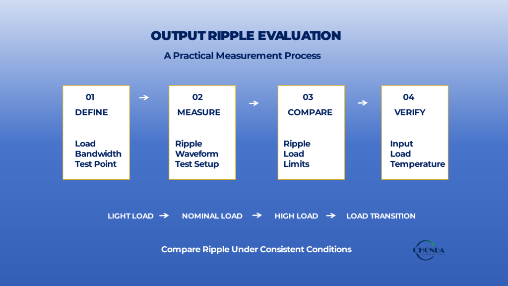
8.1 Define the Load Condition
The first step is to define the output load under which the ripple will be measured.
The test may include:
- light load
- nominal load
- high load
- maximum intended continuous load
The selected load should reflect how the converter will actually operate in the final application.
For example, measuring ripple only at 25% load may not provide enough information for a system that normally operates close to full load.
Therefore:
The load condition should be specified together with the ripple result.
8.2 Define the Measurement Bandwidth
The second step is to establish the measurement bandwidth.
Output ripple can contain components at the switching frequency, harmonics, and higher-frequency ringing.
A wider measurement bandwidth may capture more of these components, while a narrower bandwidth may exclude some of them.
Therefore, a statement such as:
Output Ripple = 30mV
is difficult to interpret unless the measurement bandwidth is also known.
For meaningful comparison, the same bandwidth should be used when evaluating different converters or operating conditions.
8.3 Define the Measurement Point and Method
Before taking the measurement, define where and how the voltage will be measured.
The test should identify whether the ripple is being measured:
At the converter output terminals
or
At the load input terminals
The measurement setup should also define:
- probe connection
- grounding method
- test-point location
- cable configuration
- oscilloscope settings
This is important because the measurement setup itself can introduce additional high-frequency signals.
A reproducible measurement method is therefore part of the ripple specification.
8.4 Measure the Ripple Waveform
Once the operating and measurement conditions are defined, measure the actual output waveform.
Do not look only at a single numerical value.
The waveform can provide useful information about the nature of the ripple, including whether it appears:
- periodic
- high-frequency
- low-frequency
- irregular
- accompanied by ringing
A waveform view can help engineers identify whether the dominant issue is associated with switching behavior, filtering, control response, parasitic effects, or the measurement setup.
8.5 Compare Ripple With the Actual Load Requirement
The next step is to determine whether the measured ripple is acceptable for the application.
The appropriate target depends on the downstream load.
For example, monitoring electronics, measurement circuits, communication systems, and control electronics may have different sensitivity to output-voltage variation.
Therefore, converter selection should not be based simply on:
“Which converter has the lowest ripple?”
Instead, ask:
“Is the converter’s ripple performance appropriate for the actual load requirement?”
This avoids over-specifying the converter when a less restrictive ripple level is already sufficient for the application.
8.6 Evaluate Under Multiple Operating Conditions
After the initial measurement, repeat the test across the intended operating range.
A practical sequence is:
Light Load
↓
Nominal Load
↓
High Load
↓
Load Transition
This helps determine whether ripple changes significantly with operating condition.
The engineer can then identify whether the dominant ripple behavior occurs under:
- low-load operation
- normal operation
- high-load operation
- changing-load conditions
This is more informative than relying on a single test point.
8.7 Evaluate Input Voltage as Well
Output ripple should also be checked at relevant input-voltage conditions.
A high voltage DC-DC converter may operate from a wide input range, and the output waveform can change as the input operating point changes.
A practical evaluation may therefore include:
Minimum Input
Nominal Input
Maximum Input
combined with representative load conditions.
This provides a more realistic view of how the output behaves across the converter’s operating envelope.
8.8 Check Temperature and Steady-State Conditions
Temperature can also influence output-ripple behavior through changes in capacitor characteristics, magnetic components, switching behavior, and control performance.
Therefore, where the application requires long-term operation under elevated temperature or high load, ripple should be evaluated after the converter has reached a representative steady-state thermal condition.
The objective is to avoid relying only on measurements taken immediately after startup.
8.9 Compare Converters Under Equivalent Conditions
When evaluating different high voltage DC-DC converters, the test conditions should be as comparable as possible.
A useful comparison table might include:
| Test Parameter | Converter A | Converter B |
|---|---|---|
| Input Voltage | Defined | Same |
| Output Voltage | Defined | Same |
| Load | Defined | Same |
| Switching Frequency | Record | Record |
| Measurement Bandwidth | Same | Same |
| Measurement Point | Same | Same |
| Ripple | Record | Record |
| Temperature | Record | Record |
Without equivalent conditions, a lower reported ripple value may simply reflect a different test setup.
Therefore:
Compare measurement conditions before comparing ripple numbers.
8.10 A Practical Ripple-Evaluation Process
The complete evaluation can be summarized as:
Define Load
     ↓
Define Bandwidth
     ↓
Define Test Point & Method
     ↓
Measure Ripple
     ↓
Compare With Load Requirement
     ↓
Repeat Under Multiple Conditions
     ↓
Confirm Suitability
This process helps separate three different questions:
What ripple does the converter produce?
What ripple does the application allow?
Does the converter remain suitable across the intended operating range?
These questions should be answered separately before final converter selection.
8.11 Key Takeaway
A useful output-ripple evaluation is not simply a measurement of millivolts on an oscilloscope.
It is a defined process that connects the converter operating condition, measurement method, and actual load requirement.
The practical sequence is:
Define Load → Define Bandwidth → Measure Ripple → Compare With Load Requirement → Evaluate Under Multiple Conditions
This approach produces a more meaningful basis for converter selection and helps prevent misleading comparisons based on ripple values measured under different conditions.
The final section will bring these points together by examining common output-ripple design mistakes and a practical checklist for engineers selecting a high voltage DC-DC converter.
9. Common Design Mistakes and Final Checklist
Output ripple is often treated as a single specification value, but a meaningful evaluation requires the converter, output filter, load, measurement method, and operating environment to be considered together.
Several common mistakes can lead to misleading ripple measurements or an inappropriate converter selection.
9.1 Measuring Output Ripple Under Only One Load Condition
One common mistake is measuring ripple at only a single load level and assuming that the result represents the converter’s behavior across its entire operating range.
For example, a converter may show one ripple waveform at 25% load and a different waveform near full load because output current, capacitor ripple current, control behavior, and temperature have changed.
Therefore, engineers should consider ripple at representative operating points such as:
Light Load → Nominal Load → High Load
For applications with rapidly changing loads, load-transition conditions should also be evaluated.
A single load point does not necessarily describe the complete output-ripple behavior of a converter.
9.2 Ignoring Measurement Bandwidth
Another common mistake is reporting an output-ripple value without defining the measurement bandwidth.
The measured waveform may contain:
- switching-frequency components
- harmonics
- high-frequency spikes
- parasitic ringing
A wider bandwidth may capture more of these components, while a narrower bandwidth may exclude some of them.
As a result, the reported ripple value can change even when the converter itself has not changed.
Therefore, the measurement bandwidth should be clearly defined and kept consistent when comparing operating conditions or different converters.
9.3 Comparing Ripple Numbers Without the Same Test Conditions
A reported ripple value is meaningful only when the conditions under which it was measured are understood.
For example:
Converter A: 30mV ripple
Converter B: 50mV ripple
This comparison is incomplete unless the input voltage, output load, measurement bandwidth, measurement point, probe connection, temperature, and other relevant conditions are sufficiently comparable.
Engineers should therefore compare the test setup and operating conditions before comparing the numerical ripple values.
9.4 Selecting a Capacitor Only by Its Capacitance
A common design mistake is to assume that a larger capacitance value will automatically produce lower output ripple.
Capacitance is important, but other characteristics also influence the final result.
These include:
- ESR
- ESL
- ripple-current capability
- voltage rating
- temperature characteristics
- aging behavior
A capacitor with a large nominal capacitance may still be unsuitable if its ESR, ripple-current capability, or thermal characteristics do not match the application.
Therefore:
Capacitance should be considered together with the complete electrical and thermal characteristics of the capacitor.
9.5 Treating Ripple Independently From EMI
Output ripple and EMI are not identical parameters, but they can be influenced by related switching behavior and high-frequency current paths.
A converter may therefore require both:
Output-voltage quality evaluation
and
EMI / EMC evaluation
Reducing a measured output-ripple component does not automatically mean that the converter has achieved the desired electromagnetic-compatibility performance.
Likewise, an EMI issue should not automatically be interpreted as an output-ripple problem.
The two should be evaluated separately while recognizing their interaction within the power architecture.
9.6 Treating Ripple Independently From Thermal Performance
Output ripple should also be considered together with thermal conditions.
As load increases, the converter and output-filter components may experience higher losses and temperature.
Temperature can affect capacitor characteristics, magnetic components, and other parts of the output network.
Therefore, ripple measured immediately after startup may not fully represent the waveform after the converter reaches a stable operating temperature.
For demanding applications, ripple should be evaluated under representative steady-state thermal conditions.
9.7 Treating Ripple Independently From Output Regulation
Output ripple should not be confused with output regulation.
A converter may maintain its average output voltage close to the target value while still exhibiting measurable periodic ripple.
Conversely, a converter can have relatively low ripple while experiencing an undesirable change in its average output voltage under different operating conditions.
Therefore, both should be evaluated:
Output Regulation → How accurately is the target output maintained?
Output Ripple → How much periodic variation remains around that output?
They describe different aspects of converter performance.
9.8 Ignoring the Complete Output Path
The voltage observed at the converter terminals may not be exactly the same as the voltage seen by a remote load.
PCB traces, connectors, cables, additional filters, and load-side capacitance can all influence the final waveform.
Therefore, engineers should decide early whether the requirement applies to:
Converter Output
or
Load-Side Voltage
This distinction is particularly important when the converter supplies a sensitive load through relatively long wiring.
9.9 A Final Output-Ripple Checklist
Before approving a high voltage DC-DC converter, engineers can review the following:
| Check | Question |
|---|---|
| Load condition | Has ripple been evaluated at more than one representative load? |
| Input voltage | Has ripple been checked across the relevant input range? |
| Measurement bandwidth | Is the bandwidth clearly defined? |
| Measurement point | Is it clear where the ripple is measured? |
| Probe / grounding | Is the measurement setup controlled and repeatable? |
| Capacitor | Were capacitance, ESR, ESL, and ripple-current capability considered? |
| Temperature | Was ripple evaluated under representative thermal conditions? |
| Regulation | Was output ripple evaluated separately from output regulation? |
| EMI / EMC | Have ripple and EMI been evaluated as related but distinct requirements? |
| Load-side behavior | Does the actual load see the same output waveform as the converter terminals? |
| Comparison | Are competing ripple specifications based on equivalent test conditions? |
9.10 Key Engineering Principle
Output ripple should ultimately be treated as part of the complete converter and load system, rather than as a single isolated number.
A practical evaluation connects:
Switching Behavior
→ Output Filter
→ Control Architecture
→ Load Condition
→ PCB / Cable Effects
→ Measurement Method
→ Output Ripple
The final objective is not necessarily to achieve the smallest possible ripple under every condition.
It is to ensure that the converter provides an output waveform that is appropriate for the actual load while maintaining acceptable regulation, EMI behavior, thermal performance, and long-term reliability.
Meaningful ripple evaluation requires consistent test conditions and a clear connection between converter performance and the requirements of the final application.
High Voltage DC-DC Solutions for Application-Specific Output Requirements
In high voltage DC-DC converter applications, output ripple needs to be considered together with output voltage regulation, load conditions, thermal performance, EMI, and the requirements of the downstream equipment.
CHONDA develops high voltage DC-DC power modules for industrial applications requiring regulated DC output across a wide range of input conditions. Depending on the application, converter selection can take into account input voltage range, output voltage, power level, isolation requirements, load characteristics, thermal conditions, and output-performance requirements.
For application-specific projects, these parameters can be evaluated together to determine whether a standard power module is suitable or whether a customized converter design is required.
Conclusion
Output ripple is an inherent part of practical DC-DC conversion and is influenced by switching behavior, magnetic current variation, output capacitors, control architecture, load conditions, physical layout, and measurement technique.
A useful evaluation therefore goes beyond a single ripple number.
Engineers should define the operating conditions, use a repeatable measurement method, compare the result with the actual load requirement, and verify performance across the relevant input, load, and thermal range.
This system-level approach provides a more reliable basis for selecting and designing high voltage DC-DC converters for industrial applications.