We help the world since 2012

How to Mount a Toroidal Transformer in Industrial Equipment
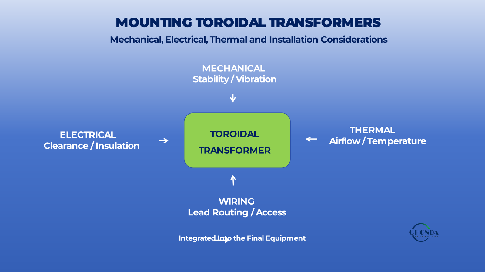
Installing a toroidal transformer may appear straightforward because of its compact circular shape and relatively simple mounting structure.
However, correct mounting is more than simply securing the transformer to a chassis or enclosure.
The mounting method can affect:
- Mechanical stability
- Vibration resistance
- Electrical insulation
- Creepage and clearance
- Heat dissipation
- Lead routing
- Serviceability
- Long-term reliability
A toroidal transformer can therefore meet its voltage and VA requirements and still create a problem if the mounting arrangement is not compatible with the final equipment.
For example, the transformer may physically fit inside the enclosure but leave insufficient clearance around the winding leads.
A metal mounting component may also create an unintended electrical relationship with the transformer structure.
Likewise, an installation method that provides good mechanical support may restrict the transformer’s ability to transfer heat to the surrounding environment.
The correct mounting approach should therefore be considered as part of the complete equipment design.
A typical installation can be viewed as:
Toroidal Transformer → Mounting Structure → Enclosure / Chassis → Electrical and Thermal Environment
The engineer needs to consider all of these relationships rather than treating mounting as an isolated mechanical task.
Different applications may use different approaches, including center-bolt mounting, brackets, custom mechanical supports, or application-specific mounting hardware.
The appropriate choice depends on the transformer dimensions, equipment structure, vibration environment, insulation requirements, thermal conditions, and production method.
This guide explains the main considerations when mounting a toroidal transformer in industrial equipment, including mechanical space, mounting methods, insulation, vibration, thermal performance, lead routing, and common installation mistakes.
The goal is not simply to make the transformer stay in place.
It is to achieve a secure, electrically safe, thermally practical, and serviceable mounting arrangement that remains reliable throughout the intended operating life of the equipment.
1. Why Toroidal Transformer Mounting Matters
Mounting a toroidal transformer is not simply a matter of keeping the transformer physically fixed.
The mounting structure becomes part of the environment in which the transformer operates, and it can influence mechanical stability, electrical insulation, thermal behavior, lead routing, and long-term reliability.
This is particularly important in industrial equipment, where the transformer may operate continuously while being exposed to vibration, temperature changes, limited installation space, and other nearby electrical or mechanical structures.
1.1 Mechanical Stability
The primary purpose of mounting is to keep the transformer securely positioned.
A toroidal transformer has a circular geometry and can have significant mass relative to its size.
If the mounting structure is insufficient, the transformer may move during:
- Equipment transportation
- Mechanical vibration
- Fan operation
- Motor operation
- Repeated thermal cycling
A stable mounting arrangement helps prevent movement that could damage the transformer, its leads, or surrounding components.
1.2 Vibration Can Create Long-Term Stress
A transformer that appears stable during initial assembly may still experience mechanical stress over time.
Repeated vibration can affect:
- Mounting hardware
- Lead connections
- Insulation materials
- Transformer positioning
- Nearby components
For industrial equipment, the mounting method should therefore be selected with the expected mechanical environment in mind.
The requirement is not only:
Can the transformer be mounted?
It is:
Can the mounting arrangement remain stable throughout the intended operating life?
1.3 Mounting Hardware Can Become Part of the Electrical Environment
Mounting hardware may include metal bolts, washers, brackets, chassis structures, or other conductive components.
These parts can come close to the transformer core, winding insulation, or electrical connections.
The mounting arrangement should therefore maintain appropriate electrical separation and avoid creating unintended conductive or capacitive paths.
This becomes particularly important when the transformer has demanding primary-to-secondary isolation requirements.
1.4 Mounting Can Affect Creepage and Clearance
The physical position of the transformer influences the available space around its terminals and leads.
A transformer that fits inside an enclosure may still be incorrectly positioned if:
- Primary and secondary leads are too close
- Conductive mounting hardware reduces clearance
- The transformer is too close to a metal enclosure
- Other conductive components create an unintended path
The mounting location and hardware should therefore be reviewed together with the insulation requirements.
1.5 Mounting Can Affect Thermal Performance
A toroidal transformer generates heat through core and winding losses.
How it is mounted can influence how that heat is transferred to the surrounding environment.
For example, the transformer may be:
Mounted in Open Air
or:
Installed Inside a Compact Enclosure
The available airflow, surrounding components, and contact with mounting structures can all affect the thermal environment.
A mounting structure should therefore provide adequate mechanical support without creating an unnecessarily restrictive thermal condition.
1.6 Installation Space Is More Than the Transformer Footprint
The nominal transformer dimensions do not represent the complete space requirement.
The equipment may also need room for:
- Mounting hardware
- Lead exits
- Electrical clearance
- Insulation barriers
- Cable routing
- Service access
For this reason, the mounting envelope is usually larger than the transformer’s outer dimensions alone.
This is particularly important in compact industrial equipment.
1.7 Lead Stress Can Come From the Mounting Arrangement
If the transformer is positioned poorly, its leads may need to bend sharply or travel around nearby structures.
Repeated mechanical stress at the lead exit can eventually affect the connection.
A good mounting arrangement should therefore allow the leads to leave the transformer naturally without excessive bending or tension.
The mounting decision and lead-routing decision should be made together.
1.8 Mounting Should Consider the Surrounding Equipment
A toroidal transformer rarely operates as an isolated component.
It may be installed next to:
- PCB assemblies
- Power modules
- Heat sinks
- Capacitors
- Relays
- Connectors
- Metal enclosure walls
The mounting location should therefore consider the space and operating conditions of the surrounding equipment.
Moving the transformer a small distance may improve mechanical access while also changing thermal, electrical, or wiring conditions.
1.9 Serviceability Matters
Industrial equipment may need to be inspected, repaired, or replaced during its service life.
A mounting method that makes the transformer extremely difficult to access can increase service time and introduce unnecessary maintenance risk.
Engineers should therefore consider whether the transformer can be:
- Installed efficiently
- Removed safely
- Replaced without disturbing unrelated components
- Accessed without compromising nearby wiring
The best mounting method is not always the one that requires the fewest fasteners.
It is the one that provides an appropriate balance between security, assembly, and serviceability.
1.10 Mounting Method Should Match the Application
Different applications create different mounting requirements.
For example:
Stationary Industrial Equipment
may prioritize secure fastening and simple assembly.
Equipment With Significant Vibration
may require additional mechanical consideration.
Compact Enclosures
may prioritize height, lead exit, and clearance.
High-Temperature Installations
may require greater attention to airflow and thermal paths.
The mounting method should therefore be selected from the actual application conditions rather than from the transformer’s shape alone.
1.11 Mounting Is Part of Transformer Integration
A useful way to view the complete installation is:
Transformer
↓
Mounting Structure
↓
Electrical + Thermal + Mechanical Environment
↓
Final Equipment
This means that mounting should be considered during the equipment design stage rather than after the transformer has already been selected.
1.12 The Practical Engineering Principle
The key point is:
A toroidal transformer is properly mounted only when it is mechanically secure, electrically safe, thermally practical, and compatible with the surrounding equipment.
A mounting arrangement that solves only the mechanical fastening problem may still create electrical-clearance, lead-routing, thermal, or serviceability issues.
The next step is therefore to examine the actual mechanical space available before selecting a mounting method, including diameter, height, center opening, and surrounding clearance.
2. Check the Mechanical Space Before Mounting
Before selecting a mounting method for a toroidal transformer, engineers should first confirm that the transformer can be physically integrated into the available equipment space.
The transformer dimensions are only part of the requirement.
The complete mounting envelope also needs to include the space required for mounting hardware, lead exits, electrical clearance, insulation, cable routing, and access for assembly or maintenance.
A practical approach is therefore:
Transformer Dimensions → Mounting Envelope → Surrounding Clearance → Final Equipment Fit
2.1 Outer Diameter
The outer diameter is one of the first dimensions to check.
A toroidal transformer may fit comfortably within the nominal width of an enclosure while still interfering with:
- PCB assemblies
- Mounting brackets
- Cooling structures
- Cable channels
- Enclosure walls
- Nearby components
The available installation area should therefore be compared with the transformer’s actual outer diameter rather than estimated visually.
2.2 Overall Height
Height can become an even stronger limitation in compact electronic equipment.
A transformer may have an acceptable diameter but still exceed the available vertical space once the mounting hardware, insulation structures, and lead exits are included.
The engineer should therefore consider:
Transformer Height + Mounting Hardware + Required Clearance
rather than the transformer height alone.
This is particularly important when the transformer is installed below a PCB or inside a shallow enclosure.
2.3 Center Opening
The center opening is a distinctive mechanical feature of a toroidal transformer.
Depending on the mounting method, the opening may need to accommodate:
- A mounting bolt
- A support rod
- Mechanical hardware
- A cable route
- Other structural elements
The center opening should therefore be checked against the selected mounting hardware before finalizing the transformer dimensions.
A transformer can have the correct outer dimensions and still be incompatible with the intended mounting structure if the center opening is unsuitable.
2.4 Mounting Envelope
The actual space required is usually larger than the transformer itself.
A simplified mounting envelope can be considered as:
Transformer Body + Mounting Hardware + Lead Exit + Safety Clearance
This envelope should be reserved during the mechanical design stage.
For compact industrial equipment, this can prevent a common problem in which the transformer technically fits but leaves insufficient space for wiring or safe electrical separation.
2.5 Surrounding Clearance
The transformer should not be designed into the enclosure as a component that simply touches whatever space remains.
Adequate clearance may be required between the transformer and:
- Metal enclosure walls
- PCB conductors
- High-voltage components
- Connectors
- Other transformers
- Heat-generating components
The required distance depends on the electrical and thermal requirements of the application.
The final clearance should therefore be established from the applicable design requirements rather than from an arbitrary visual gap.
2.6 PCB Clearance
When a toroidal transformer is installed close to a PCB, the board layout needs to account for the transformer’s physical envelope.
The engineer should consider:
Transformer Diameter
Transformer Height
Lead Exit
Mounting Hardware
Nearby PCB Components
A transformer that overlaps the nominal PCB area may interfere with components located on the opposite side of the board or restrict access during assembly.
2.7 Lead Exit Space
The lead exit is easy to overlook during mechanical layout.
The transformer may have sufficient space for its body, but the wires may need additional room to leave the winding area and route toward the connector or terminal.
The design should therefore reserve space for:
- Lead bending
- Insulation
- Strain relief
- Cable routing
- Primary / secondary separation
A transformer should not be considered mechanically integrated until the lead path is also practical.
2.8 Mounting Hardware Clearance
A center-bolt mounting system, for example, requires space not only for the bolt but also for associated washers, insulating components, nuts, or support structures.
These parts may extend beyond the nominal transformer body.
The mounting hardware should therefore be included in the mechanical envelope from the beginning.
2.9 Clearance From Heat Sources
Mechanical space should also be evaluated together with the local thermal environment.
Installing a toroidal transformer immediately next to a heat sink, power semiconductor, resistor bank, or another transformer can increase its local ambient temperature.
Even if the transformer physically fits, the location may not be thermally suitable.
The available space should therefore be evaluated for both:
Mechanical Fit
and:
Thermal Separation
2.10 Service and Assembly Access
The transformer may need to be installed, wired, inspected, or replaced.
The mechanical design should therefore provide reasonable access to:
- Mounting hardware
- Primary leads
- Secondary leads
- Connectors
- Insulating components
A mounting arrangement that is technically possible but extremely difficult to assemble may increase production time and maintenance effort.
2.11 Enclosure Tolerance and Manufacturing Variation
The mechanical design should also account for manufacturing tolerances.
For example, a nominal enclosure dimension may not represent the exact available space after:
- Sheet-metal tolerances
- PCB placement tolerances
- Connector tolerances
- Transformer dimensional variation
- Assembly tolerances
A design with essentially zero clearance may therefore create interference during production even when the nominal dimensions appear compatible.
2.12 Mechanical Fit Should Be Checked Before Final Transformer Selection
The final selection process should therefore verify:
Outer Diameter
Height
Center Opening
Mounting Envelope
Lead Exit Space
Electrical Clearance
Thermal Separation
Assembly / Service Access
Only after these constraints are understood should the engineer choose the most appropriate mounting method.
2.13 When Mechanical Constraints Justify a Custom Toroid
If a standard toroidal transformer meets the electrical requirements but cannot fit the available space, customization may become a practical option.
For example:
Correct VA + Correct Voltage
but:
Height Too Large
can create a genuine integration problem.
Likewise:
Correct Electrical Specification
but:
Incorrect Center Opening / Lead Exit
may make the standard transformer difficult to install.
In such cases, a custom toroidal transformer can be considered as an alternative to redesigning the surrounding equipment.
2.14 The Practical Engineering Principle
The key point is:
The transformer should be evaluated using its complete mounting envelope, not just its nominal diameter and height.
A successful mechanical integration must leave enough space for the transformer body, mounting structure, leads, electrical separation, thermal conditions, and practical assembly.
The next step is to examine the common mounting methods used for toroidal transformers and determine which approach is most appropriate for the equipment structure.
3. Common Toroidal Transformer Mounting Methods
Once the available mechanical space has been confirmed, the next step is to select a mounting method that provides adequate mechanical stability while remaining compatible with the electrical, thermal, and safety requirements of the equipment.
Several mounting approaches can be used for toroidal transformers.
The most appropriate method depends on the transformer size, enclosure structure, vibration environment, insulation requirements, available space, and production method.
Common approaches include:
Center-Bolt Mounting
Bracket Mounting
Application-Specific Mechanical Support
The mounting method should be selected as part of the complete equipment design rather than simply according to the transformer’s shape.
3.1 Center-Bolt Mounting
Center-bolt mounting is one of the most common approaches for toroidal transformers.
A bolt passes through the center opening of the transformer and secures the transformer to the equipment structure.
A simplified arrangement is:
Transformer → Insulating / Mounting Components → Chassis → Fastener
This method is attractive because it is relatively simple, compact, and easy to integrate into many enclosure structures.
It is especially practical when the transformer has a suitable center opening and the equipment provides a stable mounting surface.
The detailed considerations for center-bolt installation are discussed in the next section.
3.2 Bracket Mounting
Bracket mounting uses a mechanical support structure to hold the transformer in position.
This can be useful when:
- A center-bolt arrangement is inconvenient
- The available enclosure geometry does not support center mounting
- The transformer needs a specific orientation
- Additional mechanical support is required
A bracket can also allow the transformer to be positioned relative to nearby PCB assemblies, cooling structures, or enclosure walls.
However, the bracket itself becomes part of the mechanical and electrical environment.
Its material, position, fastening method, and relationship to the transformer should therefore be considered carefully.
3.3 Custom Mechanical Support
Some equipment cannot accommodate a conventional mounting arrangement.
For example, the transformer may need to fit into a highly constrained enclosure or share space with other components.
A custom support structure may then be used to achieve:
- Specific transformer positioning
- Controlled clearances
- Defined lead routing
- Additional vibration support
- Improved service access
This approach is particularly useful when the equipment geometry is application-specific.
However, the support should not create excessive mechanical stress on the transformer or interfere with insulation, cooling, or wiring.
3.4 Potting or Encapsulation in Some Applications
Some applications may use encapsulation or potting as part of the transformer assembly.
This can provide additional:
- Mechanical stability
- Environmental protection
- Vibration resistance
- Contamination protection
However, encapsulation can also influence thermal behavior and serviceability.
It should therefore be considered only when the environmental or mechanical requirement justifies the additional structure.
The appropriate material and process depend on the transformer design and application requirements.
3.5 Mounting Through the Center Opening
A key advantage of toroidal transformers is the center opening, which can support compact mechanical fastening.
However, the mounting hardware should not be treated as simply a metal rod passing through the transformer.
Depending on the transformer construction, the mounting system may need to include appropriate insulating or protective components to maintain the required electrical separation.
The exact arrangement depends on the transformer design and applicable safety requirements.
3.6 Avoid Excessive Mechanical Pressure
The transformer should be secured firmly enough to prevent movement, but excessive clamping force can create unnecessary mechanical stress.
Excessive pressure may affect:
- Core structure
- Insulation materials
- Transformer windings
- Mounting hardware
- Long-term mechanical stability
The mounting system should therefore provide secure retention without treating the transformer as a component that can simply be clamped as tightly as possible.
3.7 Mounting Surfaces Should Be Stable
The equipment surface supporting the transformer should provide sufficient mechanical rigidity.
A flexible or poorly supported mounting structure may allow the transformer to move during vibration or transportation.
This can create repeated stress on:
- Leads
- Fasteners
- Insulation
- Surrounding structures
The mechanical support should therefore be designed around the expected operating and transportation environment.
3.8 Mounting Method and Transformer Size
The appropriate mounting approach may also change with transformer size.
A relatively small transformer may be adequately supported by a simple mounting arrangement.
A larger or heavier transformer may require more substantial mechanical support or additional structural reinforcement.
The weight of the transformer should therefore be considered together with:
Mounting Structure + Fasteners + Expected Vibration
rather than evaluating the transformer weight alone.
3.9 Mounting Method and Production Requirements
The preferred mounting method can also depend on how the equipment is manufactured.
A high-volume production system may prioritize:
- Fast assembly
- Repeatable positioning
- Simple fastening
- Easy inspection
A lower-volume industrial system may accept a more application-specific mounting structure if it provides a better technical fit.
The mounting method should therefore balance engineering performance with the practical assembly process.
3.10 Mounting Method Should Not Be Selected in Isolation
Each approach has different implications.
Center-Bolt
→ Simple and compact
Bracket
→ Flexible positioning
Custom Support
→ Application-specific integration
Encapsulation / Potting
→ Additional mechanical and environmental protection
None of these is universally best.
The correct choice depends on the complete relationship between the transformer and the equipment.
3.11 A Practical Mounting Selection
Before selecting the mounting method, engineers should ask:
Is the center opening suitable for the required hardware?
Can the transformer be securely supported?
Is the mounting structure electrically safe?
Will the installation leave adequate clearance?
Will the mounting method interfere with cooling?
Can the transformer withstand the expected vibration and handling?
Is the method practical for assembly and service?
These questions help identify the most appropriate mounting approach before detailed hardware is finalized.
3.12 The Practical Engineering Principle
The purpose of the mounting method is not simply to hold the transformer in place.
It should provide:
Mechanical Stability + Electrical Safety + Thermal Compatibility + Practical Integration
A good mounting solution secures the transformer while preserving the conditions required for reliable operation.
The next section examines the most common approach—center-bolt mounting—in more detail, including the role of insulating components, washers, fasteners, and mounting surfaces.
4. Center-Bolt Mounting: The Most Common Approach
Center-bolt mounting is one of the simplest and most widely used methods for securing a toroidal transformer.
The basic concept is straightforward:
Toroidal Transformer → Center Bolt → Mounting Structure
However, the mechanical simplicity of the method does not mean that the installation can be designed without further consideration.
The center-bolt arrangement must provide secure mechanical retention while maintaining appropriate insulation, avoiding excessive mechanical stress, and preserving the required electrical and thermal conditions around the transformer.
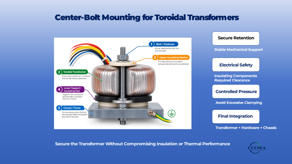
4.1 Basic Center-Bolt Arrangement
A typical installation uses the transformer’s center opening to locate a fastener through the middle of the toroid.
A simplified structure may include:
Upper Insulating / Mounting Washer
↓
Toroidal Transformer
↓
Lower Insulating / Mounting Washer or Support
↓
Chassis / Mounting Surface
↓
Bolt / Nut Assembly
The exact arrangement varies with the transformer construction and equipment design.
The important point is that the transformer should be supported securely without compromising the electrical or mechanical requirements of the assembly.
4.2 The Center Opening Must Match the Hardware
Before selecting the bolt or mounting hardware, confirm that the center opening provides sufficient space for the intended fastening arrangement.
The engineer should consider:
- Bolt diameter
- Washer dimensions
- Insulating components
- Assembly tolerance
- Required clearance
The hardware should fit without contacting parts of the transformer in a way that could damage the winding insulation or create an unintended conductive path.
4.3 Use Appropriate Insulating Components
In applications where the mounting structure is conductive, insulating components may be required between the transformer and the metal hardware.
Depending on the design, these may include:
- Insulating washers
- Shoulder washers
- Sleeves
- Insulating pads
- Other approved insulating structures
The purpose is to maintain the required electrical separation and prevent the mounting hardware from creating an unintended connection to the transformer windings or other electrical domains.
The exact insulation arrangement should be determined from the transformer construction and the applicable safety requirements.
4.4 Do Not Assume the Core Is Electrically Equivalent to the Winding
A toroidal transformer contains several physical structures, including the magnetic core, winding insulation, outer wrapping, and leads.
The electrical relationship between these parts depends on the transformer construction.
The mounting design should therefore not assume that the core or outer surface can be treated as an arbitrary grounded or ungrounded conductor.
The transformer’s actual construction and insulation system should be understood before choosing conductive mounting hardware.
4.5 Clamping Force Should Be Controlled
A center-bolt system must hold the transformer firmly enough to prevent movement.
However, excessive clamping force can place unnecessary mechanical stress on the transformer.
The objective is:
Secure Retention
without:
Excessive Compression
The appropriate fastening method and mechanical force depend on the transformer size, mounting hardware, support structure, and manufacturer guidance.
Where a supplier specifies a particular mounting procedure or allowable fastening condition, that guidance should take priority.
4.6 Use a Stable Mounting Surface
The chassis or mounting plate supporting the transformer should be sufficiently rigid.
A flexible mounting surface can allow movement during:
- Transportation
- Vibration
- Equipment operation
- Thermal cycling
Movement can place additional stress on the fastener, transformer, or leads.
A stable mounting surface helps keep the transformer in its intended position throughout operation.
4.7 Avoid Direct Pressure on the Winding Area
The clamping system should distribute mechanical force appropriately.
A mounting structure that concentrates force on a small area of the transformer can create unnecessary stress on the outer winding structure or insulation.
Suitable washers or support components can help distribute the load more evenly.
The objective is to secure the transformer through a controlled mechanical interface rather than compressing the winding structure directly.
4.8 Check the Bottom and Top of the Transformer
The complete installation should be reviewed in three dimensions.
Engineers should check the available space:
Above the Transformer
for:
- PCB clearance
- Cable routing
- Mechanical structures
Below the Transformer
for:
- Chassis hardware
- PCB conductors
- Insulation
- Fastener structures
Around the Transformer
for:
- Enclosure walls
- Nearby components
- Thermal airflow
- Electrical clearance
A transformer that appears to fit from the top view may still create a problem when the complete three-dimensional installation is considered.
4.9 Keep Primary and Secondary Leads Clear
The center-bolt hardware should not interfere with the transformer leads.
Primary and secondary wiring should remain appropriately separated according to the insulation and safety requirements of the application.
The installation should also avoid:
- Sharp bending
- Pinching
- Excessive tension
- Contact with metal edges
The lead routing should allow the wires to leave the transformer naturally and reach their connection points without unnecessary mechanical stress.
4.10 Check the Relationship With the Chassis
If the transformer is mounted to a metal chassis, the relationship between the transformer and chassis should be explicitly understood.
The chassis may serve as:
- Mechanical support
- Protective-earth structure
- Heat-spreading structure
- EMC reference
These functions can interact.
For example, a mechanical mounting point may also become part of an electrical return path if conductive coupling is present.
The mounting system should therefore be reviewed together with the grounding and insulation architecture.
4.11 Vibration and Transportation Conditions
A toroidal transformer can experience significant mechanical loading during transportation even when the equipment is stationary during normal operation.
The mounting method should therefore be able to tolerate the expected:
- Shock
- Vibration
- Handling
- Transportation conditions
The design should prevent movement that could damage the transformer, insulation, or lead connections.
For equipment with significant vibration, the mechanical retention method may need additional engineering beyond a basic center-bolt arrangement.
4.12 Thermal Effects Should Also Be Considered
The center-bolt arrangement can influence the local thermal environment.
Depending on the mounting structure, the chassis or support hardware may contribute to heat spreading.
However, the installation may also restrict airflow or place the transformer near other heat sources.
The engineer should therefore verify that the mounting method does not unintentionally increase the transformer’s operating temperature.
The mechanical support, enclosure, and cooling arrangement should be considered together.
4.13 Follow the Transformer Manufacturer’s Mounting Guidance
There is no universal center-bolt arrangement that applies to every toroidal transformer.
The permissible hardware, insulating components, clamping method, and mounting orientation depend on the specific transformer construction.
Where the manufacturer provides:
- Mounting instructions
- Approved hardware
- Insulation requirements
- Fastening recommendations
- Maximum tightening conditions
these should be followed.
The general principles in this guide should be treated as a design framework rather than as a substitute for application-specific instructions.
4.14 When Center-Bolt Mounting Is a Good Fit
Center-bolt mounting is particularly attractive when:
The Transformer Has a Suitable Center Opening
The Enclosure Has a Stable Mounting Surface
The Required Clearance Can Be Maintained
The Mounting Hardware Is Compatible With the Insulation System
The Vibration Environment Is Manageable
In these conditions, the method can provide a compact and practical solution with relatively simple assembly.
4.15 When Another Mounting Method May Be Better
Center-bolt mounting may become less attractive when:
- The center opening is unavailable or unsuitable
- The enclosure geometry makes center access difficult
- The transformer requires a specific orientation
- Vibration requirements are unusually demanding
- The mounting hardware conflicts with insulation requirements
- The available mechanical structure does not provide adequate support
In these cases, a bracket or application-specific support may provide a better solution.
4.16 The Practical Engineering Principle
The key point is:
A center-bolt mounting system should secure the toroidal transformer without creating excessive mechanical stress or compromising its electrical, thermal, or insulation requirements.
The bolt itself is only one part of the mounting system.
The complete design includes:
Fastener + Washers / Insulation + Mounting Surface + Transformer + Surrounding Structure
Once these elements have been considered together, center-bolt mounting can be a simple and reliable solution for many industrial applications.
The next step is to examine how the mounting arrangement should be evaluated when the equipment is exposed to vibration, shock, and long-term mechanical movement.
5. Insulation and Safety Around the Mounting Hardware
The mounting hardware of a toroidal transformer is part of the physical installation and can therefore affect the electrical safety of the complete assembly.
A bolt, washer, bracket, chassis, or other conductive structure may be positioned very close to the transformer and its windings.
If the mounting arrangement is not compatible with the transformer’s insulation system, a mechanically secure installation can still create an electrical safety problem.
The mounting system should therefore be evaluated as part of the complete insulation and safety structure.
5.1 Conductive Hardware Requires Careful Evaluation
Many toroidal transformers are mounted using metal fasteners because metal provides strong mechanical support.
However, conductive hardware can create an unintended electrical relationship with the transformer or surrounding equipment.
Before using a metal bolt, washer, or bracket, engineers should determine:
What is the electrical relationship between the mounting hardware and the transformer?
Is the hardware intended to be grounded, isolated, or electrically floating?
Could it reduce the required clearance or creepage?
These questions should be answered from the actual transformer construction and equipment safety requirements.
5.2 Insulating Washers and Sleeves
Insulating components are often used to control the electrical relationship between the transformer, fasteners, and chassis.
Depending on the mounting arrangement, these may include:
- Insulating washers
- Shoulder washers
- Sleeves
- Insulating pads
- Barrier components
Their purpose is not simply to “make the mounting safer.”
They are used to maintain a defined insulation structure while still allowing the transformer to be mechanically secured.
The exact components should be selected according to the transformer construction and applicable requirements.
5.3 The Chassis May Have Several Functions
In industrial equipment, the chassis may simultaneously act as:
Mechanical Support
Protective-Earth Structure
EMC Reference
Thermal Structure
These functions can interact.
For example, a metal chassis may provide excellent mechanical support while also becoming part of a conductive or capacitive path.
The transformer mounting arrangement should therefore be reviewed together with the chassis grounding and insulation architecture.
5.4 Clearance Around the Mounting Hardware
The fastener itself needs sufficient physical separation from nearby conductive or electrical structures.
The engineer should check the distance between:
- Mounting bolt
- Washer
- Transformer leads
- Winding structures
- PCB conductors
- Chassis features
- Other high-voltage components
A mechanically small gap may become electrically important depending on the working voltage and applicable safety requirements.
Clearance should therefore be established from the relevant electrical requirements rather than from mechanical convenience.
5.5 Creepage Can Be Affected by Mechanical Parts
Creepage is measured along a surface.
This means that a washer, bracket, mounting plate, or other mechanical structure can affect the available creepage path.
The physical arrangement should therefore be evaluated to ensure that the mounting hardware does not unintentionally shorten the required surface distance between conductive parts.
This is particularly important when the transformer provides isolation between primary and secondary circuits.
5.6 Do Not Assume the Mounting Hardware Is Automatically Grounded
A common design assumption is:
Metal hardware = ground
This is not necessarily correct.
The electrical relationship between a mounting bolt, transformer core, shield, chassis, and protective earth depends on the actual design.
Connecting a mounting component to ground without understanding the transformer construction can create an unintended current path or compromise the intended insulation structure.
Grounding decisions should therefore be intentional.
5.7 Primary and Secondary Leads Need Separate Attention
The mounting hardware is not the only concern.
The primary and secondary leads must also maintain the required electrical separation after the transformer has been installed.
A lead that was safely positioned during factory assembly may be routed differently once it enters the equipment.
The installation should therefore prevent:
- Primary-to-secondary contact
- Lead pinching
- Contact with sharp metal edges
- Excessive bending
- Loss of insulation
- Reduced clearance near mounting hardware
5.8 Mounting Hardware Should Not Damage the Insulation
Mechanical fastening can create an electrical problem if it damages the transformer insulation.
For example, an incorrectly positioned washer or sharp-edged hardware could place localized pressure on the transformer structure.
Similarly, excessive tightening could deform insulating materials or create mechanical stress around the mounting region.
The hardware should therefore be selected and installed so that the insulation remains intact throughout the expected service life.
5.9 Safety Distances Must Consider the Complete Installation
The transformer itself may satisfy an insulation requirement before installation.
However, the final equipment adds:
Mounting Hardware + Chassis + PCB + Wiring + Connectors
These structures can change the actual electrical distances.
The final installation should therefore be evaluated as a complete assembly rather than assuming that the transformer’s standalone dimensions automatically guarantee the required safety spacing.
5.10 Isolation and Mounting Are Closely Connected
For an isolated transformer, the mounting arrangement should preserve the intended boundary:
Primary Domain → Isolation Barrier → Secondary Domain
The mounting hardware and surrounding structures should not unintentionally create a new conductive connection across that boundary.
This is particularly important when the transformer is installed on a metal chassis or close to other grounded structures.
5.11 Safety Requirements Depend on the Application
The required insulation and spacing depend on factors such as:
- Working voltage
- Transient environment
- Pollution conditions
- Insulation system
- Equipment category
- Applicable standards
For this reason, there is no single universal washer, bolt, or clearance dimension that should be applied to every toroidal transformer installation.
The applicable requirements should be determined for the actual equipment.
5.12 Mounting and Safety Should Be Designed Together
A practical installation review can therefore follow:
Select Mounting Method
↓
Identify Conductive Structures
↓
Define Electrical Relationship
↓
Check Clearance / Creepage
↓
Verify Lead Separation
↓
Confirm Insulation Under Assembly Conditions
↓
Validate the Complete Installation
This prevents mechanical fastening from being treated separately from electrical safety.
5.13 The Practical Engineering Principle
The key point is:
A toroidal transformer mounting system must provide mechanical support without compromising the transformer’s insulation structure or creating unintended electrical paths.
The bolt, washer, bracket, chassis, and leads should therefore be considered as parts of one installation system.
A secure mounting method is only successful when it remains mechanically stable and electrically safe throughout the intended operating life.
6. Mechanical Stress, Vibration, and Stability
A toroidal transformer may remain mechanically stable during initial assembly and still experience stress over the operating life of the equipment.
Industrial equipment can be exposed to vibration, shock, repeated transportation, thermal cycling, or other mechanical forces.
The mounting system should therefore be designed not only for initial installation, but also for the conditions the transformer is expected to experience throughout its service life.
6.1 Vibration During Normal Operation
Some industrial equipment operates near motors, fans, pumps, compressors, switching mechanisms, or other sources of mechanical vibration.
Even relatively small continuous movement can become significant when it is repeated over a long period.
A suitable mounting arrangement should prevent the transformer from:
- Shifting
- Rotating
- Loosening
- Rubbing against nearby structures
The objective is to maintain a stable mechanical position without placing unnecessary stress on the transformer.
6.2 Shock and Transportation Loads
Equipment may experience higher mechanical forces during transportation than during normal operation.
For example, a transformer may be subjected to:
- Handling shock
- Packaging impact
- Equipment movement
- Installation forces
A mounting structure that is adequate for a stationary operating environment may therefore need additional consideration for transportation and installation.
The transformer should remain securely supported without transferring excessive shock directly into the winding or insulation structure.
6.3 Repeated Thermal Cycling
A transformer expands and contracts as its temperature changes.
In equipment that repeatedly starts, stops, or experiences large temperature changes, this can create repeated mechanical movement between:
Transformer + Mounting Hardware + Chassis
Over many cycles, this may contribute to loosening, mechanical fatigue, or stress around leads and insulating structures.
Thermal cycling should therefore be considered when evaluating long-term mounting reliability.
6.4 Mounting Hardware Can Loosen Over Time
A fastening system that appears secure during assembly may experience changes under vibration and thermal cycling.
The engineer should therefore consider:
- Fastener type
- Mechanical locking method
- Washer arrangement
- Mounting-surface rigidity
- Expected vibration
The objective is to maintain the intended clamping condition throughout the expected service life.
Where a specific transformer or mounting hardware manufacturer provides installation guidance, that guidance should be followed.
6.5 Avoid Excessive Clamping
Mechanical stability does not mean maximum possible clamping force.
Excessive force can place unnecessary stress on the transformer structure.
The mounting system should provide enough retention to prevent movement while avoiding excessive compression of the transformer or insulating materials.
This is particularly important for installations that use central clamping through the toroidal opening.
6.6 Prevent Transformer Movement
A toroidal transformer should ideally remain in its intended position after installation.
Uncontrolled movement can create several secondary problems.
For example:
Transformer Movement
→ Lead Bending
→ Insulation Wear
→ Mechanical Contact
→ Possible Long-Term Reliability Problem
The mounting system should therefore control both vertical movement and lateral or rotational movement where necessary.
6.7 Lead Connections Are Mechanically Sensitive
The transformer leads are often one of the most flexible parts of the assembly.
If the transformer moves relative to the PCB, terminal, or connector, the leads may experience repeated bending or tensile loading.
Over time, this can place stress on:
- Lead terminations
- Solder joints
- Connector contacts
- Wire insulation
The transformer should therefore be mounted so that the leads do not have to carry mechanical loads created by transformer movement.
6.8 Use Appropriate Strain Relief Where Needed
When the transformer leads connect directly to a PCB, terminal, or connector, the installation may benefit from controlled strain relief.
The purpose is to prevent external cable forces from being transferred directly into the transformer winding or termination area.
This is especially useful when the equipment contains:
- Long internal wires
- Heavy cable assemblies
- Frequently serviced connections
- Significant vibration
The exact strain-relief method depends on the equipment and lead configuration.
6.9 Surrounding Components Should Not Become Mechanical Stops
A transformer should not be installed so closely to nearby components that those components unintentionally become part of its mechanical support.
For example, the transformer should not rely on:
- PCB edges
- Capacitors
- Heat sinks
- Enclosure walls
- Wiring bundles
to prevent movement unless those structures have been intentionally designed for that purpose.
Uncontrolled contact can create mechanical wear and may transfer vibration into other components.
6.10 Mounting Surface Rigidity Matters
A strong transformer mounted to a flexible sheet or weak bracket may still move significantly during vibration.
The mounting structure should therefore have sufficient rigidity for the transformer’s mass and the expected mechanical environment.
A practical review should consider:
Transformer Mass + Mounting Geometry + Fastener Arrangement + Expected Vibration
rather than looking at the transformer alone.
6.11 Orientation Should Be Mechanically Stable
The mounting orientation may influence how mechanical forces are transferred to the transformer.
For equipment that experiences vibration or shock, the orientation should be chosen so that the transformer is securely supported and the mounting hardware does not experience unnecessary leverage.
The orientation should also remain compatible with lead routing, insulation, and thermal requirements.
6.12 Vibration and Electrical Safety Can Interact
Mechanical movement can also create an electrical safety issue.
For example, repeated movement may:
- Reduce spacing
- Stress insulation
- Pull leads toward nearby conductive parts
- Create rubbing against metal structures
A mounting solution should therefore prevent movement that could change the electrical relationship between the transformer and the surrounding equipment.
6.13 Long-Term Reliability Requires a Stable Mechanical System
For industrial equipment, reliability is not determined only by whether the transformer works immediately after assembly.
The mounting arrangement should remain effective after:
Transportation + Installation + Vibration + Thermal Cycling + Long-Term Operation
This is particularly important for equipment expected to remain energized for long periods or operate with repeated mechanical activity.
6.14 A Practical Mechanical Review
Before finalizing the mounting design, engineers should ask:
Will the transformer remain fixed during normal vibration?
Can it withstand expected transportation shock?
Could thermal cycling loosen or stress the mounting system?
Are the leads protected from repeated mechanical movement?
Is the mounting surface sufficiently rigid?
Could any surrounding component accidentally become a mechanical support point?
Does movement during the expected service life threaten insulation or electrical clearance?
These questions help distinguish an installation that is merely secure during assembly from one that is robust over time.
6.15 The Practical Engineering Principle
The key point is:
A toroidal transformer mounting system should be designed for the complete mechanical life of the equipment, not only for the moment of assembly.
The transformer should remain securely positioned without excessive clamping force, lead stress, or uncontrolled movement under vibration, shock, and thermal cycling.
The next step is to examine how the mounting arrangement affects the transformer’s thermal environment and whether the installation allows the transformer to dissipate heat effectively.
7. Thermal Considerations During Installation
A toroidal transformer generates heat during normal operation, but the amount of heat that can be removed depends partly on how the transformer is installed.
The same transformer can therefore operate at different temperatures in different equipment configurations.
An installation that provides good mechanical support but restricts airflow, traps heat, or places the transformer next to other high-temperature components may increase the transformer’s operating temperature.
For this reason, mounting should be evaluated together with the surrounding thermal environment.
7.1 The Transformer Does Not Operate in Isolation
The transformer releases heat through its core, windings, outer surfaces, and surrounding structures.
Once installed inside equipment, the available thermal environment is influenced by:
- Airflow
- Enclosure size
- Nearby heat sources
- Mounting surfaces
- Component spacing
- Ambient temperature
The thermal condition seen by the transformer is therefore determined by the complete installation rather than by the transformer alone.
7.2 Open-Air and Enclosed Installation Can Behave Differently
A transformer operating in open air may have relatively favorable heat dissipation conditions.
The same transformer installed inside a compact enclosure may experience a higher local temperature because heat accumulates within the enclosed space.
A simple comparison is:
Open Installation → Better Heat Exchange
versus:
Restricted Enclosure → Greater Thermal Accumulation
This difference should be considered when determining the practical continuous loading of the transformer.
7.3 Do Not Use Rated VA Without Considering the Installation
A transformer may have a specified VA rating under defined operating conditions.
That rating should not automatically be interpreted as the amount of power the transformer can deliver under every installation condition.
For example, the usable continuous load may be influenced by:
Ambient Temperature + Enclosure + Airflow + Mounting Arrangement
If the actual equipment environment is more restrictive than the reference condition, additional thermal margin may be required.
7.4 Nearby Heat Sources Can Raise Local Temperature
A toroidal transformer may be installed close to:
- Power semiconductors
- Heat sinks
- Resistors
- Power modules
- Other transformers
- Motors or actuators
These components can increase the local ambient temperature around the transformer.
In a compact enclosure, several heat sources can also interact.
The transformer should therefore be evaluated based on the temperature of its actual surrounding environment rather than assuming that the external room temperature represents the transformer’s local condition.
7.5 Keep Thermal Space Around the Transformer
The mechanical envelope should include not only the transformer’s physical dimensions but also reasonable space for heat exchange.
Avoid placing the transformer tightly against surrounding structures unless those structures are intentionally part of the thermal design.
For example:
Transformer + Enclosure Wall + Nearby PCB
may create a much more restricted thermal environment than:
Transformer + Open Surrounding Air
The required spacing depends on the equipment and cooling method.
7.6 Mounting Surface Can Help or Restrict Heat Transfer
A mounting surface can influence the thermal path.
A suitable structure may help spread heat into the enclosure or another thermal mass.
However, an insulating mounting arrangement may also reduce heat transfer through the support structure.
The mechanical interface should therefore be evaluated based on its actual thermal role.
The mounting method should not be assumed to improve cooling simply because it provides physical contact with a chassis.
7.7 Forced Air Requires a Defined Flow Path
When fans are used, the transformer should be positioned so that the available airflow can actually reach the relevant surfaces.
A simple airflow concept is:
Air Inlet → Heat-Generating Components → Transformer / Heat-Spreading Region → Air Outlet
If the transformer is placed behind a large obstruction or inside a stagnant air region, the theoretical airflow capacity of the enclosure may not provide the expected cooling benefit.
7.8 Transformer Orientation Can Influence the Thermal Environment
The mounting orientation can influence how air moves around the transformer and how heat accumulates within the local enclosure.
Orientation should therefore be evaluated together with:
- Airflow direction
- Surrounding components
- Enclosure geometry
- Lead routing
- Mounting hardware
The best orientation is the one that satisfies the complete installation requirements rather than simply the easiest mechanical orientation.
7.9 Do Not Let the Transformer Become a Heat Source for Sensitive Electronics
A toroidal transformer may be installed near:
- Control electronics
- Sensors
- Capacitors
- Communication circuits
- Temperature-sensitive components
If the transformer operates at elevated temperature, it can raise the local temperature of these neighboring components.
The installation should therefore consider not only:
Can the transformer stay cool enough?
but also:
Can nearby electronics remain within their own required temperature range?
7.10 Continuous Duty Requires Realistic Thermal Verification
A transformer used continuously should be evaluated under the actual continuous load and environmental conditions.
For example:
Rated VA + High Ambient + Restricted Airflow
can create a very different thermal condition from:
Rated VA + Moderate Ambient + Open Airflow
Short-duration tests may not show the final steady-state temperature.
A realistic validation should allow sufficient time for the transformer and surrounding structure to approach thermal equilibrium.
7.11 Thermal Conditions May Influence Derating
If the installation cannot provide the thermal conditions assumed by the transformer specification, the practical operating power may need to be reduced.
This can be viewed as:
Less Effective Cooling → Higher Temperature Rise → Reduced Practical Continuous Load
The exact derating method depends on the transformer design, specified temperature limits, and manufacturer guidance.
Derating should therefore be based on measured or appropriately calculated thermal conditions rather than an arbitrary percentage.
7.12 Mounting and Thermal Requirements Should Be Defined Together
For a compact industrial installation, the mechanical review should include:
Transformer Dimensions
Mounting Method
Available Airflow
Nearby Heat Sources
Ambient Temperature
Continuous Load
Required Temperature Margin
This allows the mechanical and electrical teams to identify conflicts early.
For example, moving the transformer only a small distance may improve airflow while also improving lead routing or electrical clearance.
7.13 Custom Dimensions Can Sometimes Improve Thermal Integration
A custom toroidal transformer may be justified when the standard mechanical envelope produces an unavoidable thermal conflict.
For example, a standard transformer may provide the required VA rating but occupy a location that blocks airflow or forces it directly beside another major heat source.
A custom height, diameter, or mounting arrangement may allow the transformer to be repositioned within the available enclosure.
In this case, the purpose of customization is not to increase the transformer rating.
It is to improve the system-level thermal and mechanical fit.
7.14 Follow the Manufacturer’s Thermal Conditions
Transformer datasheets may specify temperature limits, test conditions, mounting assumptions, or other environmental requirements.
These conditions should be understood before using the rated VA as the design target.
Where manufacturer instructions specify particular mounting or cooling conditions, those conditions should take priority over general assumptions.
7.15 The Practical Engineering Principle
The key point is:
The thermal performance of a toroidal transformer depends not only on its electrical design, but also on the environment created by the final installation.
A correct mounting design should therefore provide:
Adequate Mechanical Support + Sufficient Thermal Space + Appropriate Airflow + Acceptable Temperature Margin
The objective is to ensure that the transformer can operate continuously under the actual conditions of the equipment rather than only under a favorable laboratory setup.
The next step is to consider how primary and secondary leads should be routed after the transformer is mounted, especially where electrical clearance, insulation, and mechanical reliability must all be maintained.
9. Mounting a Toroidal Transformer in Real Industrial Equipment
Mounting a toroidal transformer inside real industrial equipment requires more than selecting a suitable fastening method.
The transformer becomes part of a larger mechanical and electrical system that may include PCBs, power modules, heat sinks, wiring harnesses, metal enclosures, connectors, and other heat-generating or electrically sensitive components.
A practical installation should therefore be evaluated as a complete integration problem:
Transformer + Mounting + Wiring + Cooling + Chassis + Surrounding Components
9.1 Start With the Complete Equipment Layout
The transformer’s final position should be considered together with the rest of the equipment.
Important neighboring structures may include:
- PCB assemblies
- Power semiconductors
- Heat sinks
- Capacitors
- Relays
- Connectors
- Cable harnesses
- Enclosure walls
A location that looks suitable when the transformer is considered by itself may become impractical once these components are installed.
The transformer should therefore be positioned from the beginning within the complete equipment layout.
9.2 Reserve the Full Installation Envelope
The space reserved for the transformer should include more than the component body.
The complete envelope should account for:
Transformer + Mounting Hardware + Leads + Electrical Clearance + Thermal Space
This prevents a common integration problem in which the transformer fits physically but leaves insufficient room for wiring, insulation, or cooling.
9.3 Consider the PCB and Chassis Together
Many toroidal transformers are installed near or on a metal chassis while their leads connect to a PCB.
This creates several interfaces:
Transformer ↔ Chassis
Transformer ↔ PCB
Transformer ↔ Wiring
Each interface should be reviewed for mechanical support, electrical separation, thermal conditions, and accessibility.
A mounting arrangement that works well for one interface may create a problem at another.
9.4 Keep High-Heat Components From Creating Local Hotspots
The transformer should be positioned with nearby heat sources in mind.
For example:
Power Semiconductor → Heat Sink → Local Hot Region
may raise the ambient temperature around the transformer if the components are placed too closely.
Likewise, the transformer itself may add heat to nearby temperature-sensitive electronics.
The final layout should therefore consider the combined thermal environment rather than evaluating each component individually.
9.5 Consider Airflow Through the Complete Enclosure
If the equipment uses forced air, the transformer location should fit within the overall airflow path.
A practical layout may look like:
Air Inlet → Power Components → Transformer / Thermal Region → Air Outlet
The exact order depends on the equipment.
The important point is that high-loss components should not unintentionally block airflow or force the transformer into a stagnant region.
9.6 Maintain Primary and Secondary Separation After Integration
The insulation relationship between primary and secondary circuits must remain controlled after the transformer is installed into the equipment.
Other components can change the available spacing.
For example:
- PCB traces may run underneath the transformer
- A metal bracket may pass near the winding
- A chassis wall may be close to the leads
- Cable bundles may cross the installation area
The final integrated structure should therefore preserve the required separation throughout the complete routing path.
9.7 Chassis Grounding Should Be Intentional
A metal enclosure may serve as a structural element, protective-earth path, EMC reference, or thermal structure.
These functions should not be assumed to be electrically interchangeable.
The engineer should define:
Which parts are intentionally grounded?
Which parts must remain isolated?
Where should high-frequency or fault currents return?
This is particularly important when the toroidal transformer is part of an isolated power system.
9.8 Keep Wiring Practical for Assembly
The final equipment should be designed so that transformer leads can be installed without excessive routing complexity.
A practical route should avoid:
- Sharp bends
- Excessive length
- Tight spaces
- Conflicting cable paths
- Difficult connector access
A clean wiring arrangement reduces assembly time and makes inspection easier.
9.9 Consider Serviceability
Industrial equipment may need transformer replacement or inspection during its service life.
The mounting arrangement should therefore provide reasonable access to:
- Fasteners
- Transformer leads
- Connectors
- Insulating components
- Surrounding hardware
A transformer buried underneath several unrelated assemblies may technically be serviceable but create unnecessary maintenance effort.
Service access should be considered before the final mounting location is fixed.
9.10 Account for Assembly Sequence
The order in which components are installed can also affect the practicality of the mounting arrangement.
For example:
Transformer Installation
↓
Fastening
↓
Lead Routing
↓
PCB Installation
↓
Final Wiring
If the final PCB or enclosure structure makes the transformer inaccessible, the assembly process may become unnecessarily difficult.
A good mechanical design considers not only the final position but also how the equipment will actually be assembled.
9.11 Consider Transportation and Handling
The finished equipment may experience shock and vibration before it reaches the end user.
The transformer mounting system should therefore remain effective during:
Factory Assembly → Packaging → Transportation → Installation → Normal Operation
The transformer should not rely on fragile surrounding structures for support.
Likewise, the leads should be protected from movement and mechanical loading during handling.
9.12 Compact Equipment Requires More Integration Planning
The more compact the equipment, the more closely related the transformer, PCB, cooling, and wiring decisions become.
A useful design process is:
Electrical Requirement
↓
Transformer Selection
↓
Mechanical Envelope
↓
Mounting Method
↓
Wiring
↓
Cooling
↓
Final Integration Check
This helps reveal conflicts before production hardware is completed.
9.13 Custom Dimensions Can Improve System Integration
If a standard toroidal transformer cannot be integrated without major compromises, a custom transformer may sometimes provide a better solution.
For example, the project may require:
Specific VA
Restricted Height
Defined Lead Exit
Specific Mounting Location
A custom transformer can potentially address these requirements together rather than forcing the equipment to accommodate an unsuitable standard shape.
The purpose of customization is therefore to improve the fit of the complete system, not simply to create a different transformer.
9.14 The Final Installation Should Be Reviewed as One System
Before production, the engineer should review the complete installation:
Mechanical
→ Is the transformer securely supported?
Electrical
→ Are insulation and clearances maintained?
Thermal
→ Is the transformer operating within the required temperature conditions?
Wiring
→ Are the leads protected and practically routed?
EMC
→ Does the installation create unnecessary coupling paths?
Service
→ Can the transformer be accessed if necessary?
These checks should be performed on the actual equipment configuration whenever possible.
9.15 The Practical Engineering Principle
The key point is:
A toroidal transformer is successfully mounted only when the mounting arrangement works together with the complete electrical, thermal, mechanical, and wiring architecture of the equipment.
The best mounting position is not necessarily the one that uses the least space.
It is the position that provides an appropriate balance between:
Mechanical Stability + Electrical Safety + Thermal Performance + Wiring + Serviceability
The final section brings these considerations together into a short practical checklist for reviewing a toroidal transformer installation before the equipment is released for production.
10. Common Mounting Mistakes and Final Checklist
Most toroidal transformer mounting problems do not come from the basic mounting method itself.
They usually result from one requirement being overlooked during mechanical integration.
A short final review can help identify these problems before the equipment enters production.
10.1 Using Only the Transformer Dimensions
A common mistake is to check only the transformer’s outer diameter and height.
The actual installation also needs space for:
- Mounting hardware
- Lead exits
- Electrical clearance
- Insulation
- Cable routing
- Thermal space
The complete mounting envelope should be checked before the transformer is installed.
10.2 Excessive Clamping Force
The transformer should be secure, but excessive tightening is not automatically better.
Too much mechanical force can place unnecessary stress on the transformer structure, insulating components, or mounting system.
The fastening method should follow the transformer manufacturer’s guidance and provide sufficient retention without unnecessary compression.
10.3 Ignoring Electrical Clearance Around Mounting Hardware
A metal bolt, washer, bracket, or chassis feature can change the available electrical spacing.
The engineer should therefore check the final assembled condition rather than assuming that the transformer itself already provides sufficient separation.
10.4 Letting Leads Carry Mechanical Loads
Transformer leads should not be used to compensate for poor positioning.
Long, short, sharply bent, or tightly routed leads can place unnecessary stress on the transformer terminations and connectors.
The wiring should have a practical routing path with appropriate support where needed.
10.5 Restricting Airflow
A transformer may fit mechanically while still being installed in a thermally unfavorable location.
Placing it too close to enclosure walls, other heat sources, or airflow obstructions can increase its operating temperature.
The final installation should therefore be checked under the actual cooling conditions of the equipment.
10.6 Ignoring Vibration and Transportation
A mounting arrangement that is stable on the assembly bench may not remain stable during transportation or long-term vibration.
The design should consider the complete mechanical environment:
Assembly → Transportation → Installation → Operation
10.7 Relying on Nearby Components for Support
A transformer should not depend on a PCB, capacitor, cable bundle, or enclosure wall to prevent movement unless that structure has been intentionally designed as part of the support system.
Unplanned contact can create mechanical wear or transfer vibration into nearby components.
10.8 Making Service Access Too Difficult
A mounting method that is extremely difficult to remove can increase maintenance time.
Where the equipment is expected to be serviced, the transformer and its mounting hardware should remain reasonably accessible without disturbing unrelated assemblies.
10.9 A Final Mounting Checklist
Before releasing the equipment for production, confirm:
Mechanical
- Transformer is securely supported.
- Mounting hardware is appropriate.
- Expected vibration and transportation loads are considered.
Electrical Safety
- Required creepage and clearance are maintained.
- Primary and secondary leads remain appropriately separated.
- Mounting hardware does not create an unintended electrical path.
- Insulation remains intact after assembly.
Thermal
- The transformer operates within the intended temperature conditions.
- Airflow is not unnecessarily restricted.
- Nearby heat sources have been considered.
Wiring
- Leads are not pinched or excessively bent.
- Lead routing does not create unnecessary mechanical stress.
- Long leads are supported where appropriate.
Integration
- The complete mounting envelope fits.
- Assembly can be performed practically.
- Service access is acceptable.
- The final equipment configuration has been reviewed.
10.10 The Practical Engineering Principle
A toroidal transformer installation is ready when it satisfies four conditions at the same time:
Secure + Safe + Thermally Practical + Serviceable
The goal is not simply to make the transformer stay in place.
It is to ensure that the mounting arrangement continues to support the transformer throughout assembly, transportation, operation, maintenance, and the expected service life of the equipment.
A simple installation can be highly reliable when these basic conditions are considered from the beginning.
Conclusion
Mounting a toroidal transformer correctly requires more than selecting a suitable fastening method.
The final installation needs to work across several requirements at the same time:
Mechanical Stability + Electrical Safety + Thermal Performance + Wiring + Serviceability
Before mounting the transformer, engineers should confirm the complete mechanical envelope, including diameter, height, center opening, mounting hardware, lead exits, and surrounding clearance.
The mounting method should then be selected according to the equipment structure and expected operating environment. Center-bolt mounting is a practical choice for many applications, while brackets or application-specific supports may be more appropriate when space, vibration, orientation, or mechanical constraints require a different approach.
The electrical relationship between the transformer, mounting hardware, chassis, and surrounding circuits should also be considered carefully. Appropriate insulation, creepage, clearance, and lead separation must remain valid after final assembly.
Thermal conditions are equally important. A transformer that performs well under favorable laboratory conditions may experience a different temperature rise when installed inside a compact enclosure with restricted airflow or nearby heat sources.
A reliable installation should therefore be evaluated across its complete life cycle:
Assembly → Transportation → Installation → Operation → Maintenance
The goal is not simply to keep the transformer in place.
It is to create a mounting arrangement that allows the transformer to operate safely, securely, and reliably within the real equipment environment for which it was designed.
How CHONDA Supports Toroidal Transformer Integration
CHONDA works with industrial equipment projects that require toroidal transformers to be integrated into specific electrical and mechanical environments.
Depending on the application, the requirement may involve:
- Defined transformer dimensions
- Specific mounting arrangements
- Custom lead length or exit configuration
- Particular primary or secondary winding requirements
- Insulation or isolation requirements
- Restricted enclosure space
- Continuous-duty or thermal constraints
The transformer should be evaluated together with the final installation rather than treated as an isolated component.
Where a standard toroidal transformer already fits the required electrical and mechanical conditions, a standard solution may be the most practical choice.
When the equipment imposes meaningful dimensional, connection, insulation, thermal, or mounting constraints, CHONDA can evaluate the application and determine whether a modified or custom toroidal transformer would provide a better fit.
The objective is to support the complete application with the appropriate transformer and mounting configuration, rather than adding customization where it is not necessary.
Related Articles
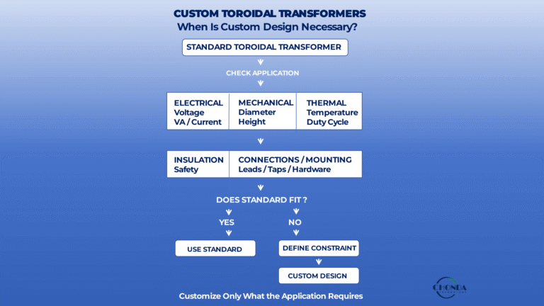
Custom Toroidal Transformers: When Is a Custom Design Necessary?
Understand when standard toroidal transformers are sufficient and when electrical, mechanical, thermal, insulation, or connection requirements justify a custom design.
High Voltage Power Supply Design Guide
Review system-level high-voltage power architecture, including conversion stages, isolation, regulation, thermal management, EMI, protection, and power-module selection.
High Power DC-DC Converters: Design & Selection Guide
Explore how higher power affects current, electrical stress, thermal performance, magnetics, switching frequency, power density, architecture, and converter selection.
High Voltage DC to Low Voltage DC Converter Design & Selection
Learn how HV-to-LV conversion architectures are selected based on input conditions, output requirements, isolation, thermal performance, protection, and integration.
EMC of AC-DC Converters: Noise Sources & Design Guide
Understand how AC-DC converter noise sources, coupling paths, common-mode and differential-mode behavior, physical design, and system conditions affect EMC performance.