We help the world since 2012

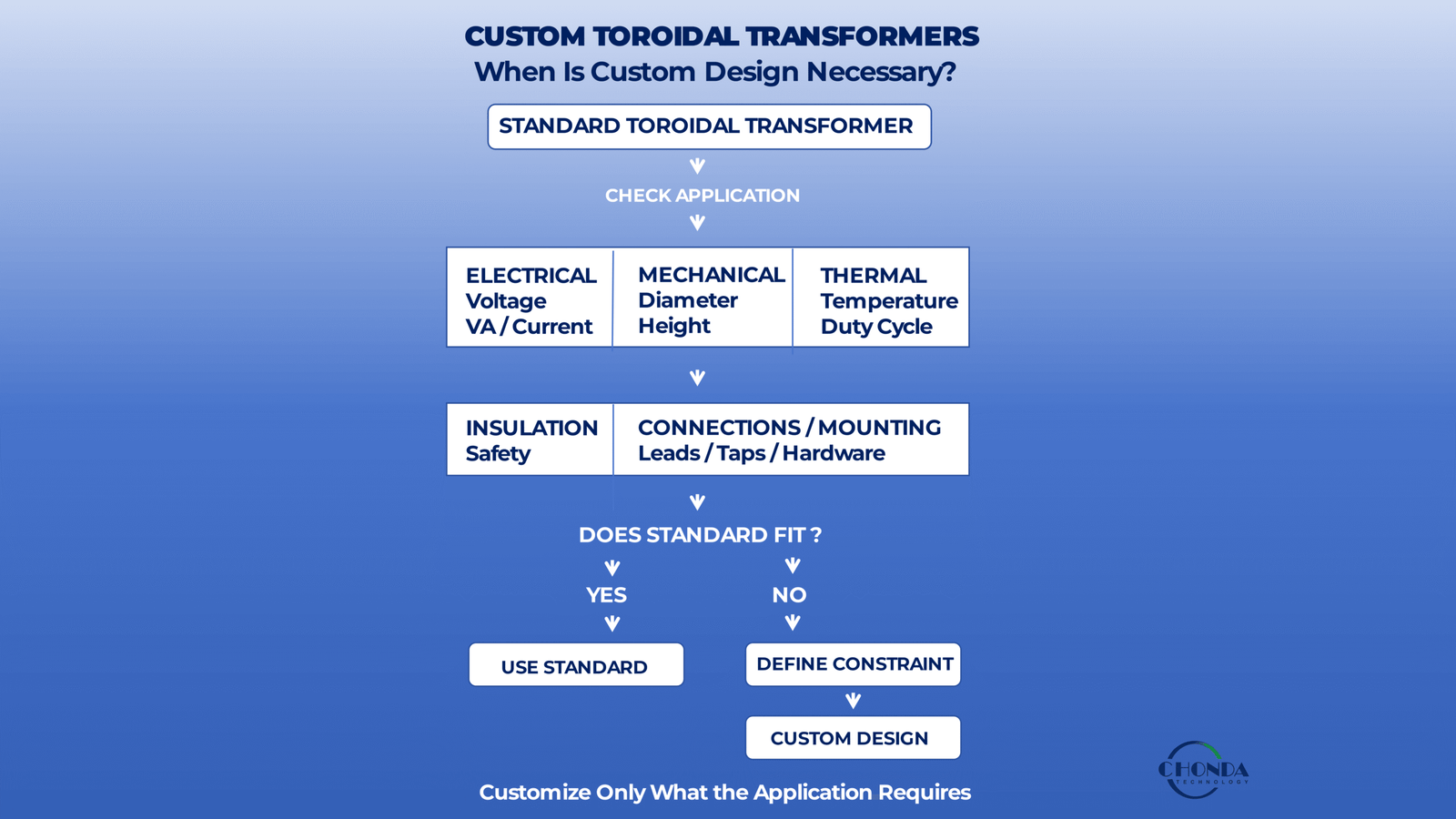
Custom Toroidal Transformers: When Is a Custom Design Necessary?
Toroidal transformers are widely used when engineers need a compact magnetic structure, low external magnetic leakage, and a reliable method of transforming AC voltage while providing the required electrical isolation.
In many applications, a standard toroidal transformer is sufficient.
However, industrial equipment does not always fit neatly within standard transformer specifications.
A project may require a specific primary voltage, unusual secondary voltage, non-standard VA rating, restricted mechanical dimensions, special mounting requirements, a particular lead configuration, or a combination of electrical and mechanical requirements that is difficult to satisfy with an off-the-shelf toroidal transformer.
This creates an important engineering question:
When is a custom toroidal transformer actually necessary?
Customization should not be treated as an automatic upgrade over a standard transformer.
A custom design becomes valuable when the application’s requirements cannot be satisfied efficiently without changing important characteristics of the transformer.
For example:
Standard Transformer → Fits Requirements → Use Standard
while:
Standard Transformer → Electrical / Mechanical Conflict → Consider Custom Design
The difference may come from voltage, power, frequency, insulation, temperature rise, physical dimensions, mounting, wiring, or the way the transformer must integrate into the final equipment.
The challenge is therefore not simply to specify a transformer with unusual numbers.
It is to determine which requirements genuinely need customization and which can be satisfied by a proven standard design.
This distinction matters because customization can introduce additional engineering work, validation requirements, tooling considerations, minimum order constraints, and development time.
A practical transformer selection process should therefore begin with the real requirements of the application and only move toward customization when the standard options no longer provide an acceptable system-level fit.
This guide explains when a standard toroidal transformer is usually sufficient, when a custom toroidal design becomes necessary, which parameters can be customized, and how engineers can make the decision without adding unnecessary complexity to the project.
1. What Makes a Toroidal Transformer “Custom”?
A toroidal transformer can be considered a custom design when its electrical, mechanical, thermal, or insulation requirements cannot be satisfied efficiently by an existing standard transformer.
This does not necessarily mean that every parameter must be unique.
In many projects, a transformer can remain largely based on a standard platform while only a few characteristics are adapted to the application.
The important engineering question is therefore:
Which requirements are truly outside the practical range of a standard toroidal transformer?
1.1 Standard Selection Comes First
A custom design should normally begin with an evaluation of available standard transformers.
If a standard toroidal transformer already provides the required:
- Primary voltage
- Secondary voltage
- VA rating
- Frequency
- Insulation
- Dimensions
- Mounting
- Lead configuration
there may be little reason to introduce a custom design.
Using a proven standard transformer can reduce development time, simplify validation, and avoid unnecessary engineering cost.
Customization becomes relevant only when one or more important requirements cannot be met without compromising the final application.
1.2 Electrical Requirements Can Drive Customization
The most obvious reason for customization is often the electrical specification.
Examples include:
- Non-standard primary voltage
- Unusual secondary voltage
- Multiple secondary windings
- Special current requirements
- Uncommon frequency
- Specific voltage regulation
- Defined no-load or full-load output behavior
For example, an application may require a secondary output that is not available from standard transformer families.
Instead of selecting a transformer with the nearest available voltage and compensating elsewhere in the system, a custom winding configuration may provide a better overall solution.
1.3 Power Rating Can Also Define the Design
The required VA rating can determine whether a standard toroidal transformer is practical.
A project may require a power level that falls between commonly available standard sizes.
In such a case, engineers may need to evaluate whether:
Nearest Standard Size → Acceptable
or:
Custom VA / Winding Design → Better System Fit
Oversizing a transformer may solve the immediate power requirement, but it can also increase:
- Physical size
- Weight
- Cost
- Inrush current
- Available installation space
Customization can therefore sometimes avoid the disadvantages of selecting a significantly oversized standard transformer.
1.4 Mechanical Requirements Can Make a Transformer Custom
A transformer may meet all of its electrical requirements and still be unsuitable because it does not physically fit the equipment.
For example, the application may require a specific:
- Outer diameter
- Height
- Mounting pattern
- Center opening
- Terminal position
- Lead exit direction
Toroidal transformers are often integrated into compact equipment where available mechanical space is tightly defined.
In such cases, mechanical customization may be just as important as electrical customization.
1.5 Lead and Connection Configuration Matters
The transformer itself may be electrically suitable while its standard connection arrangement is inconvenient for the final system.
The project may require:
- Different lead lengths
- Additional taps
- Different connector arrangements
- Specific wire gauges
- Defined lead-exit positions
- Separate secondary connections
These changes may appear relatively minor, but they can affect assembly, wiring, serviceability, and the mechanical integration of the transformer.
1.6 Insulation Requirements Can Create a Custom Design
High-voltage or industrial applications may require insulation characteristics that are not available in a standard transformer.
The design may need to consider:
Working Voltage + Dielectric Withstand + Creepage + Clearance + Insulation System
A transformer may therefore need a different winding arrangement, insulation structure, or manufacturing approach to satisfy the required electrical boundary.
This is particularly relevant when the transformer is integrated into equipment with specific safety or isolation requirements.
1.7 Thermal Requirements Can Also Be Non-Standard
The required temperature rise may depend on how the transformer is installed.
A standard toroidal transformer that performs adequately in open air may behave differently when installed:
- Inside a sealed enclosure
- Near other heat sources
- With limited airflow
- In a high-ambient environment
- In continuous-duty equipment
A custom design may therefore be appropriate when the transformer must satisfy a particular thermal limit within a restricted installation environment.
The customization may involve winding design, conductor selection, core utilization, physical dimensions, or other aspects of the magnetic structure.
1.8 Special Operating Conditions
Some applications impose operating conditions that are not well represented by a typical standard transformer specification.
Examples may include:
- Continuous energization
- Frequent power cycling
- High ambient temperature
- Restricted cooling
- Unusual source characteristics
- Specific transient conditions
In such cases, the question is not simply whether the transformer can provide the required VA.
It is whether the transformer can provide that performance under the actual operating conditions of the equipment.
1.9 Custom Does Not Mean Completely Unique
A common misconception is that a custom toroidal transformer must be designed entirely from scratch.
In practice, customization can often be incremental.
For example:
Standard Core + Custom Winding
or:
Standard Magnetic Platform + Custom Mechanical Configuration
or:
Standard Architecture + Application-Specific Insulation
This can preserve some of the advantages of a proven platform while adapting the characteristics that matter most to the application.
1.10 The Difference Between “Modified” and “Custom”
There can also be a practical distinction between a minor modification and a fully custom transformer.
For example, changing:
- Lead length
- Connector type
- Mounting hardware
may require only a limited production modification.
By contrast, changing:
- Core size
- Winding structure
- Voltage ratio
- Insulation system
- Thermal target
may require a more substantial engineering review.
The amount of customization should therefore be proportional to the problem being solved.
1.11 A Practical Customization Test
A useful way to determine whether a project genuinely requires a custom toroidal transformer is to ask:
Does the standard transformer meet the electrical requirements?
Does it fit the available mechanical space?
Does it satisfy the required insulation and safety conditions?
Can it operate within the thermal environment?
Does its connection arrangement fit the equipment?
If the answer is yes across all critical requirements, a standard transformer may be preferable.
If one or more important constraints cannot be satisfied without compromise, customization becomes more justified.
1.12 The Practical Engineering Principle
The most useful definition is:
A custom toroidal transformer is one in which one or more critical design parameters must be adapted because the standard transformer range cannot provide an acceptable fit for the intended application.
The goal of customization is not to make the transformer unusual.
It is to remove a real electrical, mechanical, thermal, or insulation constraint that would otherwise limit the performance or integration of the final equipment.
The next step is therefore to define the application’s actual electrical requirements before deciding whether a standard toroidal transformer is sufficient.
2. Start With the Real Electrical Requirements
Before deciding that a toroidal transformer requires a custom design, engineers should first define the complete electrical requirements of the application.
A transformer should not be specified only by its nominal primary and secondary voltages.
The actual design may also depend on frequency, apparent power, secondary current, regulation, duty cycle, load characteristics, and the conditions under which the transformer will operate.
A clear electrical specification is therefore the first step toward determining whether a standard toroidal transformer is sufficient.
2.1 Define the Primary Voltage
The primary voltage is the starting point of the transformer specification.
It may be a standard AC supply or an application-specific voltage generated by another power stage.
For example:
230VAC Primary
and:
115VAC Primary
represent straightforward standard conditions in many applications.
However, an industrial project may require a less common primary voltage or a transformer that must operate reliably across a defined input range.
The important point is to distinguish between:
Nominal Primary Voltage
and:
Actual Operating Voltage Range
The transformer should be selected or designed according to the voltage the equipment will actually experience.
2.2 Define the Secondary Voltage
The secondary voltage is equally important.
For a conventional transformer, the nominal secondary voltage may be specified at a particular load condition.
However, the voltage available to the downstream circuit can change with loading, winding resistance, and transformer regulation.
For example:
230VAC → 24VAC
may appear simple, but the actual requirement may be:
24VAC at Rated Load
rather than simply:
24VAC No Load
These conditions can lead to different winding requirements.
2.3 Define the Required VA Rating
The transformer power requirement is normally expressed as apparent power in VA rather than only watts.
The required VA rating should be based on the actual load.
For example:
24VAC × 5A = 120VA
provides a basic indication of the required apparent-power level.
However, the application may also include:
- Continuous load
- Intermittent load
- Startup demand
- Inrush current
- Multiple secondary loads
The transformer therefore needs to be evaluated against the actual load profile rather than simply selecting the nearest nominal VA value.
2.4 Define Secondary Current
Secondary current becomes particularly important when the output voltage is relatively low.
For example:
24VAC / 120VA = 5A
At this current level, winding design, conductor size, temperature rise, lead configuration, and terminal selection all become relevant.
Higher current can also affect voltage drop across the winding.
The required secondary current should therefore be defined together with the expected continuous and peak operating conditions.
2.5 Frequency Is Part of the Magnetic Design
Frequency should not be treated as a secondary specification.
The transformer core and winding design depend on the operating frequency.
A transformer designed for one frequency range may not provide the same magnetic performance at another.
Frequency can influence:
- Core loss
- Flux density
- Winding behavior
- Temperature rise
- Physical size
For this reason, the frequency requirement should be stated explicitly during transformer selection.
2.6 Load Type Matters
Two loads with the same nominal VA rating may place different demands on a transformer.
For example, a relatively steady resistive load may produce a different operating condition from an electronic load with a rectifier and capacitor input.
The load should therefore be described in terms of:
Nominal Power
Continuous / Intermittent Operation
Startup Behavior
Inrush
Power-Factor Characteristics, where relevant
This can be particularly important when the transformer supplies power to downstream electronics rather than a simple linear load.
2.7 Voltage Regulation Should Be Defined
Voltage regulation determines how much the secondary voltage changes between different load conditions.
For example, an application may require the transformer to maintain a certain secondary voltage under both:
Light Load
and:
Rated Load
A transformer with a higher no-load voltage may not necessarily be the best choice if the downstream circuit has a narrow acceptable voltage range.
Conversely, a transformer with very low regulation may require additional design effort or may be unnecessary for a load that naturally tolerates wider voltage variation.
The regulation requirement should therefore come from the actual application.
2.8 Continuous Duty and Intermittent Duty Are Different
A transformer operating continuously can experience a very different thermal condition from one that is energized only intermittently.
For example:
Continuous Duty
means the transformer may need to remain energized for extended periods.
By contrast:
Intermittent Duty
may allow a higher short-term load without producing the same steady-state temperature rise.
The duty cycle should therefore be included in the original specification.
This can affect the appropriate core size, winding construction, temperature target, and practical VA rating.
2.9 Multiple Secondary Windings
Some applications require more than one secondary output.
For example:
230VAC Primary
↓
24VAC Secondary A
12VAC Secondary B
6VAC Secondary C
This can sometimes be achieved with a standard transformer family, but the required combination of voltage, current, regulation, and isolation between windings may not be available in an off-the-shelf product.
Multiple secondaries can therefore become one of the reasons to consider a custom winding design.
2.10 Define Taps and Winding Relationships Carefully
A project may require taps on a secondary winding or other specific winding relationships.
For example:
24VAC Center-Tapped Secondary
can provide a different connection arrangement from a simple two-wire 24VAC output.
The required tap positions, current capability, and load usage should be defined before the transformer is designed.
A small change in winding configuration can affect the available copper space and the overall transformer construction.
2.11 Consider Tolerance and Real-World Variation
The transformer should also be evaluated against normal variation.
This may include:
- Primary-voltage tolerance
- Frequency variation
- Load variation
- Manufacturing tolerance
- Temperature variation
A specification that works only at one ideal operating point may not be robust enough for production equipment.
Custom design is sometimes justified not because the nominal values are unusual, but because the combination of tolerances and operating conditions falls outside the practical range of standard products.
2.12 A Practical Electrical Specification
Before contacting a transformer supplier or starting a custom design review, engineers should ideally define:
Primary Voltage
Primary Voltage Range
Secondary Voltage(s)
Secondary Current(s)
VA Rating
Frequency
Voltage Regulation
Continuous / Peak Duty
Load Characteristics
Taps / Connection Requirements
Required Tolerances
This gives the transformer designer enough information to determine whether an existing standard toroidal transformer is likely to be suitable.
2.13 Electrical Requirements Should Be Considered Together
The most important point is that these parameters are interconnected.
For example:
Higher Secondary Current
→ Larger Conductor Requirement
→ More Winding Space
→ Potentially Higher Thermal Load
Likewise:
Tighter Voltage Regulation
→ Different Winding Design
→ Potentially Different Copper Utilization
→ Different Transformer Construction
The transformer should therefore be specified as a complete electrical requirement rather than as a collection of unrelated numbers.
2.14 The Practical Engineering Principle
The first question in a custom toroidal transformer project should not be:
“Can you make this transformer?”
It should be:
“What does the application actually require the transformer to do?”
Once the primary voltage, secondary requirements, VA rating, frequency, load profile, regulation, and duty cycle are clearly defined, it becomes much easier to determine whether a standard transformer can meet the requirement or whether customization is genuinely justified.
The next step is to examine when a standard toroidal transformer is normally sufficient—and why customization should not be introduced unless it solves a real application constraint.
3. When Standard Toroidal Transformers Are Usually Enough
Customization is not automatically a better solution.
For many applications, a standard toroidal transformer can provide the required electrical performance, mechanical fit, insulation, and thermal capability without introducing the additional engineering effort associated with a custom design.
Starting with a standard transformer is therefore often the most practical approach.
The key question is whether the standard product already satisfies the critical requirements of the application.
3.1 Standard Electrical Ratings Already Match
A standard toroidal transformer may be sufficient when the required primary and secondary voltages, VA rating, frequency, and current already fall within an established product range.
For example:
230VAC → 24VAC / 120VA
may be a straightforward standard requirement.
If the available transformer already provides the required voltage and power under the actual load conditions, changing the winding design may provide little additional value.
3.2 The Required Secondary Voltage Is Not Especially Tight
Standard transformers often provide acceptable voltage regulation for applications where the downstream circuit can tolerate normal variation between no-load and rated-load conditions.
If the load does not require unusually tight secondary-voltage control, a standard transformer may already provide sufficient performance.
This is especially common when the transformer feeds:
- Conventional AC loads
- Simple rectifier circuits
- Control circuits with a suitable input range
- Auxiliary power circuits with reasonable voltage tolerance
The output requirement should therefore be evaluated against the actual load tolerance before customization is considered.
3.3 The VA Requirement Falls Within a Standard Range
A standard transformer is usually preferable when the required VA rating is close to an available standard size and the additional capacity does not create a significant disadvantage.
For example, if an application requires approximately 100VA and a 120VA standard transformer fits the equipment comfortably, the extra capacity may be perfectly acceptable.
The engineer should compare the practical consequences of using the next standard size before deciding that a custom rating is necessary.
3.4 The Transformer Fits the Mechanical Space
Mechanical fit is one of the main reasons a transformer becomes custom.
Therefore, if the available standard toroidal transformer already fits the required:
- Diameter
- Height
- Mounting arrangement
- Center clearance
- Lead exit location
there may be little reason to change its physical construction.
A standard transformer that fits comfortably is usually easier to integrate than a custom component that requires a new mechanical review.
3.5 Standard Mounting and Connections Are Acceptable
The same principle applies to mounting and wiring.
If the standard transformer provides a suitable:
Mounting Method
Lead Length
Terminal Arrangement
Connector Configuration
there may be no practical benefit in changing these features.
Minor inconvenience during assembly does not necessarily justify a custom transformer.
The decision should be based on whether the existing configuration creates a meaningful engineering or manufacturing problem.
3.6 Standard Insulation Meets the Application
If the standard insulation system already meets the required working voltage, dielectric withstand, creepage, clearance, and applicable safety conditions, customization may not add meaningful value.
For many conventional applications, a proven insulation structure provides a lower-risk path than introducing a new winding or insulation arrangement.
The complete final equipment must still be evaluated against its applicable requirements.
3.7 The Thermal Environment Is Conventional
A standard toroidal transformer is generally easier to use when the operating environment is similar to the conditions for which the product was designed.
For example, if the transformer is:
- Installed in a ventilated enclosure
- Operated within a normal ambient range
- Used at its intended continuous load
- Not surrounded by significant additional heat sources
the standard thermal design may already be sufficient.
Customization becomes more relevant when the application imposes unusually high ambient temperature, restricted cooling, or an unusually high continuous-duty requirement.
3.8 The Duty Cycle Is Within the Standard Design Envelope
A standard transformer may also be entirely suitable when the equipment’s operating profile matches the intended duty.
For example:
Continuous Operation at Rated Load
or:
Intermittent Operation Within the Standard Rating
can usually be handled without a custom design when the transformer is properly specified.
The critical point is to compare the actual operating profile with the transformer’s intended duty rather than assuming that “standard” automatically means unsuitable.
3.9 The Load Does Not Have Unusual Characteristics
Some loads are much harder on a transformer than their nominal VA rating suggests.
However, if the load behavior is relatively predictable and does not create unusual startup, inrush, or waveform conditions, a standard transformer may be sufficient.
The engineer should therefore distinguish between:
Unusual Load Behavior
and:
Normal Industrial Load Behavior
before deciding that custom magnetic design is required.
3.10 Development Speed Favors the Standard Solution
There is also a project-level reason to prefer standard transformers.
A standard product typically has:
- Existing design data
- Established manufacturing process
- Known performance
- Existing validation history
- Shorter engineering cycle
This can reduce development risk, particularly when the project schedule is limited.
A custom transformer may provide a better fit, but it usually introduces additional review, sampling, validation, and production considerations.
3.11 Standardization Can Reduce Project Risk
Using a proven transformer platform can also simplify future production and maintenance.
If the same transformer can be reused across several equipment versions, the engineering team may benefit from:
- Common sourcing
- Simplified inventory
- Familiar assembly procedures
- Existing qualification data
- Easier replacement
This can make standardization valuable even when a custom option could provide a marginal improvement in one parameter.
3.12 Do Not Customize to Solve a Minor Inconvenience
A useful rule is:
Do not introduce customization unless it solves a meaningful application constraint.
For example, a slightly different lead length may be inconvenient, but if the existing lead arrangement can be accommodated easily during assembly, customization may not be justified.
Likewise, selecting the next standard VA size may be more practical than commissioning a special intermediate rating.
The engineering effort should be proportional to the actual problem.
3.13 A Practical Standard-vs-Custom Test
Before requesting a custom toroidal transformer, ask:
Does a standard product meet the required electrical ratings?
Does it fit the available mechanical space?
Does its insulation system meet the application requirements?
Can it handle the real thermal environment and duty cycle?
Are the standard connections acceptable?
Can the final equipment be designed around the available standard transformer without major compromise?
If the answer is yes to the critical questions, the standard transformer is often the better engineering choice.
3.14 Standard First, Custom When Necessary
A sensible transformer-selection process can therefore be:
Define Requirements
↓
Review Standard Toroidal Transformers
↓
Check Electrical + Mechanical + Thermal + Insulation Fit
↓
Standard Solution Acceptable?
YES → Use Standard
NO → Identify the Specific Constraint
↓
Consider Custom Design
This approach prevents customization from becoming the default answer.
The purpose of a custom toroidal transformer is not to replace standard products.
It is to solve requirements that standard products cannot satisfy efficiently.
The next step is to identify the specific conditions under which a custom design becomes justified and where the standard range begins to create a meaningful engineering compromise.
4. When Does a Custom Toroidal Transformer Become Necessary?
A custom toroidal transformer becomes necessary when one or more important application requirements cannot be satisfied by a standard transformer without creating an unacceptable compromise.
The key word is necessary.
A custom design should not be requested simply because a different voltage, size, or connection would be convenient.
The decision becomes more justified when the available standard options create a meaningful problem in electrical performance, thermal behavior, mechanical integration, insulation, or overall system cost.
4.1 A Standard Voltage Does Not Match the Actual Requirement
One common reason for customization is a secondary voltage that falls outside the practical standard range.
For example, an application may require a specific voltage under rated load that cannot be achieved accurately with the available standard winding ratios.
Selecting the nearest standard voltage and compensating elsewhere may be possible, but it can introduce additional circuitry, unnecessary voltage drop, or less favorable operating conditions.
In such cases, a custom winding may provide a cleaner system-level solution.
4.2 The Required VA Rating Falls Between Standard Sizes
A custom design may also become useful when the required VA rating falls significantly between available standard transformer sizes.
For example, suppose the application requires a rating that is too high for one standard size but substantially below the next larger size.
Using the larger transformer may solve the electrical requirement, but it can also increase:
- Diameter
- Height
- Weight
- Cost
- Inrush current
- Mechanical constraints
A custom VA rating may therefore provide a better balance when the difference between the available standard sizes is significant.
4.3 Mechanical Space Can Be the Deciding Factor
Mechanical integration is often one of the strongest reasons for moving toward a custom toroidal design.
A standard transformer may have adequate electrical performance but fail to fit within the available equipment space.
For example, the design may have a strict limit on:
Outer Diameter
Overall Height
Center Opening
or:
Mounting Location
In a compact industrial enclosure, even a relatively small increase in transformer size can interfere with other components, cooling structures, or safety spacing.
Customization may therefore be justified when the standard mechanical envelope creates a real integration problem.
4.4 Multiple Secondary Windings May Require Customization
An application may require several secondary outputs with different voltage and current ratings.
For example:
24VAC / 4A
12VAC / 1A
6VAC / 0.5A
A standard toroidal transformer may not provide this exact combination.
A custom winding structure can allow the transformer to support multiple secondary requirements within one magnetic assembly.
The benefit is not simply having more outputs.
It may also include:
- Reduced component count
- Simplified wiring
- More efficient enclosure use
- Better integration with the downstream power architecture
4.5 Special Taps or Winding Configurations
Certain applications require more specific winding arrangements.
Examples include:
- Center taps
- Intermediate taps
- Multiple isolated secondaries
- Special primary configurations
- Specific series / parallel winding relationships
These requirements can affect the winding structure and therefore may not be available from a standard product.
Customization becomes more reasonable when the winding configuration is part of the functional architecture of the equipment rather than merely a preferred connection arrangement.
4.6 High Inrush or Startup Conditions
Toroidal transformers can exhibit significant inrush current depending on the core characteristics, residual flux, switching point, source impedance, and system configuration.
If the standard transformer creates startup behavior that is difficult to manage with the existing protection system, a customized magnetic design may sometimes provide a better system-level solution.
The objective is not necessarily to eliminate inrush completely.
It is to achieve startup behavior that is compatible with:
Transformer + Protection + Upstream Supply + Equipment Control
A custom design may therefore become attractive when the standard transformer’s inrush characteristics create a persistent integration problem.
4.7 Unusual Thermal Conditions
A standard transformer may also become unsuitable when the equipment operates in a significantly different thermal environment from conventional applications.
Examples include:
- High ambient temperature
- Sealed enclosure
- Restricted airflow
- Continuous high-load operation
- Nearby heat sources
The transformer may need a different winding or core design to maintain an acceptable temperature rise under these conditions.
Customization can therefore become justified when a standard transformer cannot meet the required thermal performance without substantial derating.
4.8 Higher Isolation or Insulation Requirements
Some applications require an insulation system beyond the practical configuration of standard transformers.
This may involve:
- Higher dielectric withstand
- Specific working-voltage requirements
- Additional insulation between windings
- Special creepage or clearance
- Application-specific insulation materials
In these cases, the custom design may involve not only the winding ratio but also the physical winding arrangement and insulation structure.
The relevant question is whether the complete transformer can meet the application’s insulation requirement while preserving the required electrical and thermal performance.
4.9 Restricted Lead or Connector Arrangement
A project may also require a specific connection configuration that does not fit the standard transformer.
For example:
Short Internal Leads
Defined Lead Exit Direction
Specific Connector
Multiple Terminal Groups
These details may seem minor, but they can become important when the transformer is installed in a compact assembly or when automated production requires repeatable cable routing.
Customization is more justified when the connection arrangement affects assembly, serviceability, or system reliability.
4.10 The Standard Transformer Creates Too Much Oversizing
Another common reason for customization is excessive oversizing.
A standard transformer may meet the requirement only by providing substantially more VA capacity than the application actually needs.
Oversizing can sometimes be harmless.
However, it may increase:
- Physical volume
- Weight
- Cost
- Inrush current
- Unused thermal mass
- Installation difficulty
If the oversizing is significant enough to affect the equipment design, a custom transformer may provide a more balanced solution.
4.11 Several Small Constraints Can Combine Into One Custom Requirement
A particularly important situation occurs when no single requirement is extreme, but several moderate constraints occur simultaneously.
For example:
Non-Standard Secondary Voltage
Limited Height
Multiple Secondary Outputs
High Ambient Temperature
Each requirement might be manageable independently.
Together, however, they may make the available standard products impractical.
This is often where a custom transformer provides the greatest value.
The goal is to solve the combination of constraints, not necessarily one unusual parameter.
4.12 Customization Should Solve a Defined Problem
Before starting a custom transformer project, engineers should be able to state clearly:
What cannot be achieved with the available standard transformer?
A strong custom-design requirement might be:
“The standard product exceeds the permitted height and cannot provide the required secondary voltage at rated load.”
A weak requirement might be:
“We would prefer a different size.”
The first identifies an engineering constraint.
The second identifies only a preference.
This distinction helps determine whether customization is actually justified.
4.13 A Practical Customization Trigger
A useful decision sequence is:
Standard Transformer Available
↓
Check Electrical Fit
↓
Check Mechanical Fit
↓
Check Thermal Fit
↓
Check Insulation / Safety Fit
↓
Check Connections and Integration
↓
No Significant Compromise?
→ Use Standard
Significant Constraint Remains?
→ Evaluate Custom Design
This keeps the custom option focused on solving real problems.
4.14 The Practical Engineering Principle
The most important principle is:
A custom toroidal transformer becomes necessary when the standard product range forces a meaningful compromise in one or more critical application requirements.
The purpose of customization is not to make the transformer different.
It is to make the transformer fit the application without forcing unnecessary compromises into the rest of the equipment.
The next step is to examine which transformer parameters can actually be customized and how changes in voltage, power, dimensions, and connections affect the overall design.
5. What Can Be Customized in a Toroidal Transformer?
Once a custom toroidal transformer is considered necessary, the next step is to identify which parameters actually need to be changed.
A custom transformer does not normally require every characteristic to be redesigned.
In many projects, only a small number of parameters need to be adapted while the basic magnetic concept remains similar to an established design.
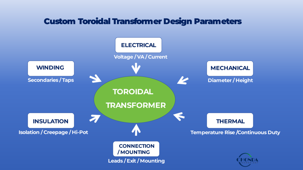
The most common customization areas include:
Voltage + Power + Dimensions + Winding Configuration + Connections
These parameters are closely related, so changing one may influence several others.
5.1 Primary and Secondary Voltage
Voltage is one of the most common customization requirements.
The primary may need to match a specific AC source, while the secondary may need to provide an application-specific voltage under a defined load condition.
For example:
230VAC → 24VAC
may be available as a standard product.
But a project may require:
230VAC → 26VAC at Rated Load
or a different combination of primary and secondary voltages.
Changing the winding ratio is therefore not simply a matter of changing one number.
The winding design must still maintain the required flux conditions, insulation, current capability, and temperature performance.
5.2 VA Rating
The required apparent power can also be customized.
A project may require a transformer rating that does not align well with standard sizes.
For example:
150VA
may fall between common standard product ratings.
A custom design can be optimized around the actual requirement rather than using a significantly oversized transformer.
However, VA rating is connected to both core capability and winding current.
Increasing VA may therefore affect:
- Core size
- Winding area
- Conductor size
- Temperature rise
- Physical dimensions
Power customization should therefore be evaluated as part of the complete magnetic design.
5.3 Outer Diameter and Height
Toroidal transformers are often selected partly because of their compact radial shape, but the available equipment space may still be tightly constrained.
A project may specify:
Maximum Outer Diameter
Maximum Height
Required Center Opening
This can become a significant design constraint.
Reducing the outer diameter or height may require changes to the core size, winding arrangement, or thermal design.
A physically smaller transformer is therefore not automatically a better transformer.
The objective is to achieve the required electrical performance within the available mechanical envelope.
5.4 Center Opening
The center opening can be particularly important for toroidal transformers because mounting hardware or mechanical structures may need to pass through it.
For example, the transformer may need to accommodate:
- A mounting bolt
- A support structure
- A cable route
- A mechanical bracket
A standard center opening may therefore be incompatible with the equipment even when the transformer meets the electrical requirements.
In such cases, the core and winding geometry may need to be adapted.
5.5 Winding Configuration
The winding arrangement can also be customized.
Possible requirements include:
- Multiple secondary windings
- Center taps
- Series-connected windings
- Parallel windings
- Separate isolated outputs
- Application-specific primary configurations
The winding configuration should be defined by how the transformer will be used in the final circuit.
A seemingly simple additional winding can consume valuable winding space and affect conductor size, insulation, leakage, and thermal behavior.
5.6 Secondary Current
A custom secondary winding may need to support a specific current level.
For example:
24VAC / 5A
requires a substantially different conductor structure from:
24VAC / 1A
even though the output voltage is identical.
Higher current may require:
- Larger conductor area
- Parallel conductors
- Different winding arrangement
- Increased winding space
- Different thermal considerations
This is one reason voltage and VA rating should always be evaluated together.
5.7 Voltage Regulation
Some applications require a specific secondary-voltage behavior between no-load and rated-load conditions.
A custom transformer can potentially be designed around the required regulation rather than simply accepting the regulation of the nearest standard product.
However, tighter regulation may influence:
- Winding resistance
- Conductor size
- Copper usage
- Physical winding arrangement
- Transformer size
The target should therefore come from the actual downstream circuit requirement.
5.8 Frequency
Frequency is another design parameter that can be customized when the application requires operation outside a conventional supply condition.
Changing frequency changes the magnetic operating point and can influence:
- Core loss
- Flux density
- Temperature rise
- Transformer size
A custom design may therefore require a different core or winding configuration when the application frequency is unusual.
The transformer must be evaluated at the actual operating frequency rather than assuming that a standard 50Hz or 60Hz design will behave identically elsewhere.
5.9 Lead Length and Exit Configuration
Customization may also involve the connection arrangement rather than the magnetic structure itself.
For example, the project may require:
Defined Lead Length
Specific Lead Exit Direction
Different Wire Gauge
Additional Taps
Dedicated Terminal Groups
These changes can simplify assembly and improve the mechanical integration of the transformer.
They may also reduce cable routing complexity inside a compact enclosure.
5.10 Mounting Arrangement
Toroidal transformers can be mounted in different ways depending on the equipment structure.
The project may require a specific mounting method or hardware arrangement.
For example:
Center-Bolt Mounting
Bracket Mounting
Isolation Mounting
The mounting system must maintain mechanical stability without creating unwanted stress on the transformer or compromising electrical insulation.
5.11 Insulation and Isolation Structure
For applications with demanding insulation requirements, customization may involve more than voltage ratio.
The transformer may require a different:
Primary-to-Secondary Insulation
Insulation Thickness
Winding Arrangement
Creepage / Clearance
Dielectric Withstand
These changes can consume additional physical space inside the winding structure.
This is one reason electrical, mechanical, and safety requirements should be reviewed together rather than independently.
5.12 Thermal Characteristics
A custom transformer may also need to meet a specific temperature-rise requirement.
For example, the application may require lower temperature rise because the transformer is installed near temperature-sensitive electronics.
The design may then require changes to:
- Conductor size
- Winding arrangement
- Core selection
- Available surface area
- Thermal path
The transformer should therefore be designed for its actual installation environment rather than only for a laboratory condition.
5.13 Customization Parameters Are Interconnected
One of the most important points is that these parameters cannot always be changed independently.
For example:
Higher VA
→ Higher Current
→ Larger Conductor Requirement
→ More Winding Space
→ Potentially Larger Core / Larger Transformer
Likewise:
Smaller Height
→ Less Available Winding Space
→ Greater Winding Density
→ Potentially Higher Thermal Stress
And:
Higher Isolation Requirement
→ More Insulation
→ Less Available Copper Space
→ Potentially Larger Physical Structure
Customization is therefore a system of trade-offs rather than a simple parameter-selection exercise.
5.14 Customization Should Focus on the Critical Parameters
A practical custom specification should distinguish between:
Must Have
and:
Preferred
For example:
Must Have
- 230VAC primary
- 24VAC secondary
- 150VA continuous
- Defined insulation
- Maximum height 50mm
Preferred
- Specific lead length
- Preferred mounting arrangement
- Minor dimensional optimization
This allows the transformer designer to focus engineering effort on the parameters that actually determine whether the transformer can be used.
5.15 A Practical Custom Specification
Before requesting a custom toroidal transformer, engineers should ideally provide:
Primary Voltage
Secondary Voltage(s)
VA / Current
Frequency
Regulation
Duty Cycle
Dimensions
Mounting
Lead / Connection Requirements
Isolation / Insulation Requirements
Operating Temperature
This specification gives the transformer designer a clear basis for determining which characteristics need to change.
5.16 The Practical Engineering Principle
The best custom toroidal transformer is not the one with the greatest number of customized parameters.
It is the one in which the critical application constraints have been customized while unnecessary changes are avoided.
A successful custom design therefore starts by identifying the few parameters that genuinely limit the standard solution and then understanding how those changes affect the rest of the magnetic, thermal, mechanical, and insulation system.
The next step is to examine isolation, insulation, and safety requirements in more detail, because these constraints can strongly influence the physical structure of a custom toroidal transformer.
6. Isolation, Insulation, and Safety Requirements
For many toroidal transformer applications, electrical isolation is one of the requirements that can significantly influence the physical design of the transformer.
A transformer may need to provide not only the required primary and secondary voltages, but also a defined electrical separation between the two windings.
When the insulation requirement becomes more demanding, the effect can extend into the core size, winding arrangement, insulation structure, available copper space, and overall transformer dimensions.
This is why insulation should be defined as part of the transformer requirement from the beginning rather than added after the magnetic design is complete.
6.1 Isolation Is More Than a Dielectric Test Number
A transformer specification may include a dielectric withstand requirement such as a defined AC test voltage.
However, this number alone does not describe the complete insulation system.
The transformer must also be considered in terms of:
- Working voltage
- Transient voltage
- Insulation system
- Creepage
- Clearance
- Temperature
- Operating environment
The dielectric test confirms performance under a specified test condition.
The insulation design must provide reliable separation during the actual operating life of the equipment.
6.2 Primary-to-Secondary Isolation
For an isolated toroidal transformer, the primary and secondary windings must maintain the required electrical separation.
A simplified structure is:
Primary Winding → Insulation System → Secondary Winding
The required insulation may involve:
- Insulation tape
- Sleeving
- Barrier layers
- Winding separation
- Reinforced insulation structures
The exact construction depends on the working voltage, safety requirements, transformer design, and applicable standards.
6.3 Insulation Takes Up Physical Space
One of the most important practical effects of insulation is that it consumes space that could otherwise be used for copper.
The available winding window must accommodate:
Copper + Insulation + Required Separation
If the insulation requirement increases, less physical space remains for the conductor.
This can force the designer to consider:
- Larger core
- Larger transformer height
- Different winding arrangement
- Different conductor structure
This is one reason a transformer that appears electrically feasible may become difficult to manufacture within a strict mechanical envelope.
6.4 Creepage and Clearance
Creepage and clearance are also relevant to the physical construction.
Clearance is the shortest distance through air between conductive parts.
Creepage is the shortest distance along the surface of an insulating material.
The required distances depend on the actual working voltage, transient environment, pollution conditions, insulation category, and applicable safety requirements.
For a toroidal transformer, the physical winding arrangement and lead configuration may therefore need to be designed around these requirements.
6.5 High-Voltage Windings May Require More Careful Construction
When the voltage difference between windings is high, the winding structure becomes increasingly important.
Engineers may need to consider:
- Layer arrangement
- Winding spacing
- Insulation barriers
- Lead routing
- End-turn spacing
- Mechanical stability
The objective is not simply to prevent an immediate electrical breakdown.
The insulation system must remain reliable during production, transportation, operation, temperature cycling, and the expected lifetime of the equipment.
6.6 Insulation and Copper Compete for the Same Winding Space
This creates a practical design trade-off:
More Insulation → Less Available Copper Space
and:
More Copper Space → Potentially Larger Magnetic Structure
If the secondary winding requires high current, the conductor may already consume a substantial portion of the available winding window.
Adding a more demanding insulation structure can then make the original core and winding geometry impractical.
This is one of the clearest reasons why insulation requirements can trigger a custom transformer design.
6.7 Multiple Secondaries Increase the Insulation Complexity
A transformer with several secondary windings may have more complicated insulation requirements than a transformer with one secondary.
For example:
Primary → Secondary A → Secondary B → Secondary C
may require controlled separation between multiple electrical domains.
If the secondaries also need different voltages, currents, or isolation relationships, the available winding space becomes increasingly important.
The final transformer may therefore need a larger core or a different winding arrangement even when the total VA rating has not changed dramatically.
6.8 Lead Configuration Is Part of the Insulation System
The winding itself is not the only part that needs to maintain the required electrical separation.
Lead exits and terminal structures can also create potential spacing constraints.
For example, the design may need to control the distance between:
- Primary leads
- Secondary leads
- Terminal pins
- Mounting structures
- Conductive chassis parts
A transformer can therefore meet its internal insulation requirement while still creating an integration issue at the connection points.
6.9 Insulation Can Affect Thermal Performance
Insulation is also part of the thermal path.
Insulating materials generally transfer heat differently from copper or the core material.
If additional insulation is required around a winding or between winding structures, the heat generated inside the winding may have a more difficult path toward the outer surface.
This creates another interaction:
Higher Insulation Requirement → Potentially More Thermal Resistance
For continuous-duty transformers, this should be evaluated together with winding losses and temperature rise.
6.10 Temperature Changes Can Affect the Insulation System
Transformer insulation needs to remain suitable over the expected operating temperature range.
The design may therefore need to consider:
- Material temperature rating
- Thermal expansion
- Mechanical movement
- Long-term aging
- Repeated thermal cycling
An insulation structure that performs well at room temperature should not automatically be assumed to behave identically after prolonged operation at elevated temperature.
6.11 Safety Requirements Can Change the Transformer Size
A common misconception is that a transformer becomes larger only when its VA rating increases.
In reality, insulation requirements can also increase the physical envelope.
For example:
Higher Working Voltage
→ More Separation
→ More Insulation
→ Less Available Winding Space
→ Potentially Larger Core / Transformer
This can happen even if the requested output power remains unchanged.
6.12 Custom Insulation Does Not Necessarily Mean a Completely New Magnetic Design
In some projects, the electrical requirements may already fit a proven magnetic platform, while only the insulation structure needs to be adapted.
For example, the transformer may retain:
Core Concept + Approximate Power Level
while modifying:
Winding Arrangement + Insulation Structure + Lead Configuration
This can be a practical way to satisfy a specialized application without redesigning every aspect of the transformer.
6.13 Safety Requirements Should Be Defined Early
A custom toroidal transformer project should ideally identify the required:
Working Voltage
Dielectric Withstand
Insulation System
Creepage / Clearance
Environmental Conditions
before the final winding structure is selected.
Late changes to insulation requirements can force redesign of the winding arrangement or physical dimensions.
This is particularly costly when the transformer has already been integrated into a tightly constrained mechanical enclosure.
6.14 The Practical Engineering Principle
The key point is:
In a custom toroidal transformer, insulation is a physical design requirement, not simply a compliance number.
Higher isolation requirements can consume winding space, change conductor arrangements, affect thermal performance, and increase the required physical envelope.
A successful custom design therefore has to balance:
Electrical Isolation + Magnetic Performance + Thermal Performance + Mechanical Fit + Safety
rather than optimizing any one of them independently.
The next step is to examine how thermal and mechanical constraints can further influence a custom toroidal transformer, especially when the transformer must operate continuously inside a compact industrial enclosure.
7. Thermal and Mechanical Constraints
A toroidal transformer that satisfies the required voltage and VA rating may still be unsuitable if it cannot operate within the thermal and mechanical conditions of the final equipment.
This is particularly important in compact industrial systems, where the transformer may be installed in a restricted enclosure, operate continuously, share space with other heat-generating components, or have limited airflow.
For this reason, thermal and mechanical requirements should be considered together with the electrical specification when evaluating a standard or custom toroidal transformer.
7.1 Temperature Rise Is Part of the Transformer Requirement
Transformer losses are eventually converted into heat.
The main sources may include:
- Core loss
- Winding loss
- Additional magnetic losses
The resulting temperature rise depends not only on the amount of loss but also on how effectively the transformer can transfer that heat to the surrounding environment.
A transformer rated for a given VA level under one installation condition may therefore behave differently under another.
7.2 Continuous Operation Changes the Thermal Requirement
A transformer used intermittently may have more opportunity to dissipate heat between operating periods.
A continuously energized transformer does not have that advantage.
For example:
Short-Duration Load → Limited Thermal Accumulation
while:
Continuous Load → Steady-State Temperature Rise
This distinction can become important when a transformer is used in industrial control equipment, monitoring systems, or other equipment expected to remain energized for long periods.
7.3 Enclosure Conditions Matter
The transformer’s thermal environment is strongly influenced by the enclosure in which it is installed.
Important factors include:
- Ambient temperature
- Airflow
- Available ventilation
- Nearby heat sources
- Mounting structure
- Enclosure size
A transformer operating in open air may have a very different temperature rise from the same transformer installed in a compact sealed enclosure.
The thermal requirement should therefore be evaluated using the final equipment conditions whenever possible.
7.4 Mechanical Clearance Can Limit Transformer Selection
Toroidal transformers are relatively compact compared with some other transformer constructions, but their circular shape still requires sufficient space around the component.
The engineer may need to reserve room for:
Outer Diameter
Height
Center Opening
Mounting Hardware
Lead Exit
Insulation / Safety Spacing
A standard transformer may satisfy the electrical specification but still be difficult to install because another component occupies the required surrounding space.
7.5 Height Can Be a Particularly Difficult Constraint
In many compact electronic assemblies, available height is more restrictive than available PCB area.
A standard toroidal transformer may have the correct diameter and VA rating while being too tall for the enclosure.
Reducing height may require changes to the core geometry, winding arrangement, or power density.
A custom design can sometimes provide a better fit than selecting a much smaller transformer and sacrificing electrical capability.
7.6 Outer Diameter and Center Opening Also Matter
The radial dimensions can be equally important.
For example, the equipment may provide a circular mounting area but have a fixed:
Maximum Outer Diameter
and:
Required Center Hole
A transformer with a slightly larger outer diameter may interfere with:
- PCB components
- Enclosure walls
- Mounting brackets
- Cooling structures
- Cable routing
The center opening may also need to accommodate a specific mounting bolt or mechanical support.
These constraints can therefore become legitimate reasons for customization.
7.7 Mounting Method Affects Thermal and Mechanical Performance
The mounting system needs to provide both mechanical stability and an acceptable thermal environment.
A typical toroidal transformer may use a center-bolt mounting arrangement, but the final equipment may require another structure.
The mounting method can affect:
- Mechanical stability
- Vibration resistance
- Contact with heat-spreading structures
- Electrical insulation
- Assembly process
The mounting hardware should therefore be considered part of the complete transformer integration rather than treated as an afterthought.
7.8 Lead Routing Can Create Integration Problems
Lead location and routing can become surprisingly important in a compact enclosure.
The transformer may need:
- A defined lead-exit position
- Specific lead length
- Different wire gauge
- Connector-based termination
- Separation between primary and secondary wiring
Long or poorly positioned leads can create unnecessary wiring complexity and may also interfere with mechanical clearance or insulation requirements.
Custom lead configuration can sometimes provide a simpler and more reliable assembly.
7.9 Thermal and Mechanical Requirements Can Conflict
A compact design often creates competing objectives.
For example:
Smaller Transformer
→ Better Packaging
but potentially:
→ Higher Thermal Density
Similarly:
Additional Mechanical Clearance
→ Better Safety / Integration
but:
→ Larger Required Installation Area
The goal is therefore not to minimize transformer size at any cost.
It is to find the smallest practical transformer that still provides the required electrical, thermal, insulation, and mechanical performance.
7.10 Nearby Components Can Change the Effective Thermal Environment
A toroidal transformer rarely operates alone.
It may be installed close to:
- Power semiconductors
- Heat sinks
- Capacitors
- Motors or actuators
- Other transformers
- Power modules
These nearby components can raise the local ambient temperature around the transformer.
Likewise, the transformer itself can become a heat source for neighboring electronics.
The thermal evaluation should therefore consider the surrounding equipment rather than using the enclosure ambient temperature as the only reference.
7.11 Mechanical Orientation and Installation Can Matter
The way the transformer is mounted can influence both thermal and mechanical behavior.
For example, the available airflow and contact with surrounding structures may change with the mounting arrangement.
The engineer should therefore verify that the proposed mounting orientation is compatible with:
- Cooling
- Mechanical stability
- Insulation
- Vibration
- Assembly requirements
A standard transformer should not be assumed to perform identically under every mounting condition.
7.12 Customization Can Solve Thermal and Mechanical Conflicts Together
A useful advantage of custom toroidal design is that electrical and physical requirements can sometimes be optimized at the same time.
For example, a project may require:
Defined VA Rating
Maximum Height
Specific Outer Diameter
Continuous Operation
Restricted Airflow
A standard transformer may satisfy the electrical requirement but exceed the permitted dimensions or temperature rise.
A custom design can then be evaluated as a complete solution rather than trying to solve each problem separately.
7.13 Do Not Optimize Size Before Understanding the Thermal Requirement
One common mistake is to begin with the smallest available transformer and then attempt to make it work.
This can create:
- Excessive temperature rise
- Limited thermal margin
- Difficult cooling
- Reduced continuous power capability
A better approach is:
Define Electrical Requirement
↓
Define Thermal Environment
↓
Define Mechanical Envelope
↓
Find the Practical Transformer Size
The physical dimensions should support the required operating conditions rather than become an independent target.
7.14 A Practical Thermal and Mechanical Review
Before approving a standard or custom toroidal transformer, engineers should confirm:
Required VA / Current
Continuous Duty
Ambient Temperature
Cooling Conditions
Maximum Diameter
Maximum Height
Center Opening
Mounting Method
Lead Exit / Connections
Nearby Heat Sources
Required Thermal Margin
This creates a much clearer basis for deciding whether the standard product is suitable.
7.15 The Practical Engineering Principle
A toroidal transformer is successfully integrated only when it fits both the electrical requirements and the physical environment of the final equipment.
The key question is therefore not:
“Is the transformer electrically rated for this application?”
It is:
“Can the transformer deliver the required performance continuously within the available mechanical space and actual thermal environment?”
When the answer is no, a custom toroidal design may be justified—not because customization is inherently better, but because the application has created a genuine thermal or mechanical constraint that the standard transformer cannot satisfy efficiently.
The next step is to examine how custom toroidal transformers can be applied in real industrial equipment and which application requirements most often lead engineers toward a custom solution.
8. Custom Toroidal Transformers in Real Industrial Applications
The need for a custom toroidal transformer often becomes clear only when the transformer is integrated into the actual equipment.
A transformer may meet the nominal electrical specification on paper and still create problems because of mechanical space, thermal conditions, insulation requirements, wiring, or the way the load behaves during operation.
For industrial applications, customization is therefore usually driven by the combination of requirements rather than by one unusual parameter alone.
8.1 Industrial Control Equipment
Industrial control systems may require transformers that provide specific AC voltages for control circuits, relays, actuators, or auxiliary electronics.
The electrical requirements may be relatively conventional, but the available enclosure space can be tightly constrained.
A standard transformer may provide the required VA rating while exceeding the permitted height or diameter.
In such cases, a custom toroidal transformer can be considered when the mechanical envelope is a genuine system constraint.
8.2 Monitoring and Measurement Systems
Monitoring equipment may require multiple secondary voltages or specific isolation relationships for different measurement and control circuits.
For example:
Primary
↓
24VAC Monitoring
12VAC Control
Separate Auxiliary Winding
A standard transformer may not provide the exact combination of voltage, current, regulation, and winding arrangement required.
A custom winding structure can therefore become useful when several electrical domains must be supported within one magnetic component.
8.3 Industrial Power Supplies and Control Cabinets
Control cabinets can contain multiple power-conversion and control components within a restricted volume.
A toroidal transformer may need to fit around:
- Mounting structures
- PCB assemblies
- Contactors
- Power modules
- Cooling equipment
The transformer may also operate continuously in an enclosure where airflow is limited.
The design requirement is therefore not simply:
Required VA
but:
Required VA + Mechanical Envelope + Thermal Environment
A custom transformer may provide a better fit when a standard model forces excessive oversizing or difficult integration.
8.4 Medical and Sensitive Electronic Equipment
Some electronic equipment places particular importance on electrical isolation, leakage-related behavior, noise, and mechanical integration.
Depending on the application, the transformer may need specific winding arrangements, insulation structures, or shielding considerations.
The design should be evaluated against the actual system requirements and applicable standards rather than assuming that a standard toroidal transformer is automatically suitable.
Customization may become valuable when the standard product cannot provide the required combination of electrical separation, mechanical dimensions, thermal behavior, and connection arrangement.
8.5 Audio and Signal-Related Equipment
Toroidal transformers are also used in some audio and sensitive electronic equipment where low external magnetic leakage and mechanical compactness are valuable.
Although this article is focused on industrial applications, custom requirements can still arise when the equipment needs:
- Specific secondary voltages
- Multiple isolated windings
- Defined VA ratings
- Low mechanical height
- Special mounting
- Particular lead configuration
The custom decision should again be based on the complete application rather than on the transformer type alone.
8.6 Automation and Embedded Systems
Automation equipment often combines control electronics, sensors, communication interfaces, and actuators within a relatively compact mechanical platform.
Different circuits may require different AC supply voltages or isolated power domains.
A custom toroidal transformer can sometimes combine several of these requirements into one magnetic component while keeping the physical package within the available space.
However, multiple windings also increase the complexity of the transformer design.
The benefit should therefore be weighed against the additional winding, insulation, and thermal requirements.
8.7 Equipment With Restricted Installation Space
One of the most common practical reasons for custom toroidal transformers is simply that the standard dimensions do not fit.
The equipment may specify:
Maximum Diameter
Maximum Height
Required Center Opening
Defined Mounting Position
When the standard transformer exceeds one of these limits, the engineering team may need to choose between redesigning the equipment and modifying the transformer.
A custom toroid becomes more attractive when changing the surrounding equipment would create greater cost or complexity.
8.8 High-Temperature or Continuous-Duty Equipment
Some industrial systems operate continuously at elevated ambient temperature.
A transformer designed for a conventional environment may then experience greater temperature rise than expected.
The custom design may need to consider:
- Winding resistance
- Conductor size
- Core characteristics
- Temperature-rise target
- Thermal path
- Available cooling
The goal is not necessarily to increase the transformer’s nominal rating.
It is to ensure that the transformer remains within an acceptable thermal condition under the real operating environment.
8.9 Applications With Unusual Input or Output Conditions
A custom toroidal transformer may also become appropriate when the electrical conditions fall outside common standard ranges.
Examples include:
- Non-standard primary voltage
- Unusual secondary voltage
- Multiple secondaries
- Special taps
- Unusual frequency
- Specific voltage regulation
The engineering value comes from matching the transformer to the actual application rather than forcing the application to compensate for an unsuitable standard winding.
8.10 High Inrush or Sensitive Upstream Protection
Some equipment has limited tolerance for transformer startup current.
If a standard toroidal transformer repeatedly causes nuisance operation of upstream protection or creates unacceptable startup disturbances, the magnetic and system design may need to be reconsidered.
The issue should first be analyzed at the system level.
If the upstream protection, switching method, and control sequence cannot adequately accommodate the standard transformer, a custom magnetic solution may become one option.
8.11 Custom Transformers Can Support Product Platforms
A manufacturer may also use one customized toroidal transformer across several related equipment models.
For example, a common transformer platform might support:
Base Model → Control Power
Expanded Model → Control + Auxiliary
Advanced Model → Control + Monitoring + Additional Output
The same basic magnetic platform can then be adapted to a family of products.
This can reduce repeated engineering work when the product family shares similar electrical and mechanical requirements.
8.12 Application Requirements Often Interact
Real industrial projects rarely have only one constraint.
A typical requirement may look like:
Specific Primary
Two Secondary Outputs
Limited Height
Continuous Duty
Defined Insulation
This combination may be difficult to satisfy with an existing standard product even if each individual requirement appears reasonable.
This is where custom toroidal transformer design often provides the most value.
8.13 A Practical Application Review
Before deciding that a custom toroid is necessary, engineers should examine:
What does the application require electrically?
Where will the transformer be installed?
How long will it operate continuously?
What is the actual ambient temperature?
What mechanical space is available?
What insulation and safety conditions apply?
What wiring and mounting arrangement is required?
Can a standard transformer meet all critical conditions simultaneously?
If the answer is no, the project has a clear basis for considering customization.
8.14 The Practical Engineering Principle
The strongest case for a custom toroidal transformer usually appears when several application requirements must be satisfied simultaneously within a constrained electrical and mechanical environment.
The objective is therefore not to create a transformer that is merely different from a standard model.
It is to create a transformer that fits the actual operating environment, system architecture, and integration requirements of the equipment.
The next step is to turn these application considerations into a practical standard-vs-custom selection process that engineers can use before starting a custom transformer project.
9. Standard vs Custom: A Practical Selection Process
The decision between a standard and custom toroidal transformer should be based on the complete application requirement rather than on a preference for one product type.
A standard transformer is usually the simplest and lowest-risk option when it satisfies all critical electrical, thermal, insulation, and mechanical requirements.
A custom transformer becomes more appropriate when the standard options create a meaningful compromise that cannot be resolved efficiently elsewhere in the system.
A practical selection process can therefore be structured as a sequence of checks.
9.1 Define the Non-Negotiable Requirements
Before reviewing transformer options, identify the requirements that cannot be compromised.
These may include:
- Primary voltage
- Secondary voltage
- VA rating
- Frequency
- Continuous duty
- Insulation requirement
- Maximum temperature rise
- Maximum diameter
- Maximum height
- Mounting arrangement
Separating must-have requirements from preferred characteristics prevents a minor preference from becoming an unnecessary custom-design request.
9.2 Review the Standard Transformer Range
The next step is to compare the application requirements with available standard toroidal transformers.
The objective is not to find the transformer with the closest single specification.
It is to determine whether one standard transformer can satisfy the complete requirement at the same time.
For example:
Correct Voltage + Correct VA
is not enough if:
Mechanical Size + Temperature Rise
cannot also be satisfied.
9.3 Check Electrical Fit
Confirm that the standard transformer provides the required:
Primary Voltage
Secondary Voltage(s)
Current
VA Rating
Frequency
Voltage Regulation
Duty Cycle
The evaluation should be performed under the actual load conditions expected in the final equipment.
A transformer that meets its nominal rating under one test condition may not provide the required secondary behavior under the real load.
9.4 Check Thermal Fit
The next question is whether the transformer can operate within the actual thermal environment.
Review:
Ambient Temperature
Continuous Load
Cooling Conditions
Nearby Heat Sources
Required Temperature Rise
If the standard transformer can meet the thermal requirement without excessive derating, this is a strong reason to stay with the standard solution.
9.5 Check Mechanical Fit
Mechanical integration should then be reviewed.
Check:
Outer Diameter
Height
Center Opening
Mounting
Lead Exit
Available Clearance
A standard transformer that fits comfortably is generally preferable to a custom transformer that requires additional design work.
However, if the equipment imposes strict dimensional limits and the standard range cannot meet them, the mechanical constraint may provide a strong justification for customization.
9.6 Check Insulation and Safety Fit
The transformer should also be reviewed against the complete insulation requirement.
Consider:
Working Voltage
Dielectric Withstand
Insulation System
Creepage
Clearance
Environmental Conditions
A standard transformer should only be considered acceptable when its insulation system fits the actual application and applicable requirements.
9.7 Evaluate the Cost of Standard Oversizing
Sometimes a standard transformer can technically meet the requirements, but only by using a substantially larger model.
The engineering team should then compare the consequences of that oversizing.
For example:
Larger Standard Transformer
may result in:
- More enclosure space
- Higher weight
- Higher cost
- Higher inrush current
- Less available space for other components
If these consequences affect the complete equipment, a custom transformer may provide a better system-level result.
9.8 Identify the Remaining Constraint
If the standard transformer fails the review, do not immediately request a completely new design.
First identify the specific constraint.
For example:
The standard transformer meets the voltage and VA requirements but exceeds the maximum height.
or:
The standard transformer fits physically but cannot provide the required secondary voltage under rated load.
This makes the customization objective clear.
9.9 Determine Whether One Parameter Can Be Changed
A custom solution may not require changing the entire transformer.
For example, the project may only need:
Custom Winding Ratio
or:
Custom Mechanical Envelope
or:
Custom Lead Configuration
A targeted modification can often provide the required result while preserving the advantages of an established magnetic platform.
9.10 Consider a Hybrid Solution
A project may also benefit from combining standard and custom elements.
For example:
Standard Core / Platform
Custom Winding
Custom Lead Arrangement
This can reduce development effort while still addressing the specific application constraint.
The goal is to customize only what needs to be customized.
9.11 Compare the Total System Impact
Before approving a custom design, compare both options at the system level.
Standard Solution
versus:
Custom Solution
Consider:
Electrical Performance
Thermal Performance
Mechanical Integration
Insulation / Safety
Development Time
Tooling / Validation
Production Volume
Cost
A custom transformer may have a higher unit cost but reduce enclosure changes or eliminate additional external components.
Conversely, a standard transformer may have a higher unit cost because of oversizing while still being the lower-risk solution.
The comparison should therefore be made using the total system impact, not transformer price alone.
9.12 Consider Production Volume
Production quantity can also influence the decision.
For a small-volume project, a standard transformer may be preferable because custom engineering and validation effort can be difficult to justify.
For a higher-volume product, customization may become more attractive if the improved fit reduces system cost, assembly effort, or enclosure size across many units.
The project economics should therefore be considered together with the technical requirement.
9.13 Consider Future Product Variants
A custom transformer may also have value when the equipment is expected to evolve.
For example, a product family may require:
Model A → 100VA
Model B → 150VA
Model C → 200VA
A transformer platform designed around the common requirements may reduce repeated redesign across the product family.
However, future requirements should be based on realistic product plans rather than assumptions that add unnecessary complexity today.
9.14 A Practical Decision Flow
The complete selection process can be summarized as:
Define Requirements
↓
Review Standard Options
↓
Electrical Fit?
↓
Thermal Fit?
↓
Mechanical Fit?
↓
Insulation / Safety Fit?
↓
No Significant Compromise
→ Use Standard
Meaningful Constraint Remains
→ Define the Constraint
↓
Targeted Modification Possible?
→ Modified / Platform-Based Solution
No
→ Evaluate Custom Design
9.15 The Practical Engineering Principle
The most reliable decision rule is:
Use a standard toroidal transformer when it satisfies the critical application requirements without significant compromise. Consider customization when a real electrical, thermal, mechanical, or insulation constraint remains after the standard options have been evaluated.
This approach keeps customization focused on solving real engineering problems rather than creating special products simply because the application allows it.
The final decision should balance technical fit, total system impact, development effort, production volume, and long-term product requirements.
10. When Customization Adds Value — and When It Does Not
A custom toroidal transformer can provide a better fit for a demanding application, but customization also introduces additional engineering, validation, manufacturing, and procurement considerations.
The best solution is therefore not always the most customized one.
The key is to determine whether customization solves a real application constraint or simply provides a preferred specification.
10.1 Customization Adds Value When It Removes a Real Constraint
A custom toroidal transformer can provide meaningful value when the standard product range cannot satisfy an important requirement without forcing a compromise.
Typical examples include:
- A non-standard primary or secondary voltage
- A specific VA or current requirement
- Multiple secondary windings
- Strict height or diameter limits
- Special insulation requirements
- Unusual thermal conditions
- Application-specific mounting or lead configuration
In these cases, customization can reduce the need for compromises elsewhere in the equipment.
10.2 Customization Does Not Add Much Value When the Standard Product Already Fits
If a standard transformer already satisfies the critical requirements for:
Voltage + VA + Insulation + Thermal Conditions + Mechanical Fit
then customization may provide little practical benefit.
A slightly different lead length or a small dimensional preference does not necessarily justify a new transformer design.
The simplest solution is often the best one when the application already fits a proven standard product.
10.3 Do Not Customize Around a Problem That Can Be Solved Elsewhere
Before starting a custom design, engineers should also ask whether the issue can be solved more efficiently through the surrounding system.
For example:
Minor Wiring Inconvenience
may be easier to solve through cable routing.
Slightly Tight Mechanical Clearance
may be easier to address through component placement.
Moderate Voltage Variation
may be manageable through the downstream circuit if its input range permits.
Customization should therefore be considered after practical system-level alternatives have been evaluated.
10.4 Consider the Total Cost, Not Only Transformer Price
A custom transformer may have a higher unit cost than a standard product.
However, the total system cost can be lower if customization eliminates:
- Additional circuitry
- Mechanical adapters
- Oversized components
- Difficult assembly
- Repeated integration work
- Excess enclosure volume
Conversely, a custom transformer may not be economical if the project volume is low and the standard product can be integrated with only minor changes.
The comparison should therefore be based on total system impact.
10.5 Development Time Is Part of the Decision
Customization usually requires additional engineering discussion, specification review, sampling, validation, and production preparation.
This can be worthwhile for a long-term product platform.
For a short development cycle or a low-volume project, however, the additional time may outweigh the benefits.
The decision should therefore consider:
Technical Benefit + Development Effort + Production Plan
10.6 A Good Custom Requirement Is Specific
A strong custom-design request should identify exactly what the standard product cannot satisfy.
For example:
“The required 24VAC output must be maintained at rated load, while the transformer height cannot exceed 45mm.”
This gives the engineering team a clear design target.
A weaker request would simply be:
“We need a special transformer.”
The more clearly the constraint is defined, the easier it is to determine whether customization is actually required.
10.7 Keep the Customization Focused
Once customization is justified, engineers should avoid changing unrelated parameters simply because the design is already being modified.
A better approach is:
Define the Critical Constraint
↓
Customize the Necessary Parameter
↓
Preserve Proven Design Elements Where Possible
This can reduce development risk and make validation easier.
10.8 Standard, Modified, or Custom?
A practical final decision can therefore be:
Standard
→ All critical requirements are already satisfied.
Modified / Platform-Based
→ A limited number of parameters need to be adapted.
Custom
→ Several important requirements fall outside the practical range of standard products.
The correct level of customization should match the level of engineering need.
10.9 Final Engineering Check
Before approving a custom toroidal transformer, ask:
What specific requirement cannot be met by the standard range?
Can the surrounding system solve the problem more simply?
Which transformer parameter actually needs to change?
Will the custom design improve the complete system?
Is the development effort justified by the project volume and lifetime?
If these questions have clear answers, the custom-design decision is based on engineering need rather than preference.
10.10 The Practical Engineering Principle
The best custom toroidal transformer is not the one with the most special features.
It is the one that solves the few critical requirements that the standard transformer cannot satisfy efficiently.
A practical decision rule is:
Standard when it fits. Modify when a limited change solves the problem. Customize when the application contains genuine constraints that require a different transformer design.
This approach keeps the engineering effort focused, avoids unnecessary complexity, and gives the final transformer a clear purpose within the complete equipment architecture.
Conclusion
A custom toroidal transformer is not necessarily better than a standard transformer.
In many applications, a proven standard toroidal transformer can provide the required electrical performance, insulation, thermal capability, and mechanical fit with less engineering effort and lower development risk.
Customization becomes valuable when the standard transformer range creates a meaningful compromise in one or more critical application requirements.
A practical decision process can therefore be summarized as:
Define the Application Requirements
↓
Review Standard Toroidal Transformers
↓
Check Electrical + Thermal + Mechanical + Insulation Fit
↓
Standard Solution Acceptable?
→ Use Standard
Meaningful Constraint Remains?
↓
Identify the Specific Constraint
↓
Consider Modified or Custom Design
The most common reasons for customization include non-standard voltage or VA requirements, multiple secondary windings, strict mechanical dimensions, unusual thermal conditions, specific insulation requirements, and application-specific mounting or connection arrangements.
The objective is not to make a transformer different from a standard product.
It is to create a transformer that fits the actual electrical, thermal, mechanical, and safety requirements of the final equipment without introducing unnecessary compromises elsewhere in the system.
For industrial applications, the best transformer solution is therefore usually the one that achieves the required performance with the lowest necessary level of customization.
Standard when it fits. Modify when a limited change solves the problem. Customize when genuine application constraints require it.
How CHONDA Supports Custom Toroidal Transformer Requirements
CHONDA works with industrial and electronic equipment projects that require toroidal transformers with application-specific electrical or mechanical characteristics.
Depending on the project, the requirement may involve a non-standard primary or secondary voltage, a specific VA rating, multiple secondary windings, defined insulation requirements, restricted dimensions, special lead configurations, or other integration constraints.
The first step is to determine whether an existing standard transformer can satisfy the complete application.
When a standard solution creates a meaningful electrical, thermal, insulation, or mechanical compromise, CHONDA can evaluate the required specifications and help determine whether a modified or custom toroidal transformer is more appropriate.
The objective is not to customize every transformer.
It is to provide the right level of customization for the actual application requirement, while preserving proven design characteristics wherever possible.